2010 JAGUAR XFR key
[x] Cancel search: keyPage 297 of 3039

Rear Suspended Tow
When the vehicle is being recovered by rear suspended tow:
The ignition key must be removed from the ignition switch to lock the steering.
The rear wheels must be correctly positioned in the lifting cradle and securely tied down.
Emergency Towing
WARNING: If the engine is not running, the steering will become heavy and the force necessary to effectively apply the
brakes will be greatly increased.
CAUTION: A vehicle with a defective transmission must be towed by rear suspended tow.
When the vehicle is being towed on its own wheels:
Local regulations for the towing of vehicles must be followed. In some countries the registration number of the towing
vehicle and an 'On Tow' sign or warning triangle must be displayed at the rear of the towed vehicle.
The gear selector lever must be in Neutral.
The ignition switch must be in position II to release the steering lock and make the direction indicators, horn and stop
lamps operate.
A distance of 0,8 km (0.5 mile) must not be exceeded.
A speed of 48 km/h (30 mph) must not be exceeded.
The tow rope must be attached to the front towing eye. www.JagDocs.com
Page 336 of 3039

Front Suspension - Front Shock Absorber
Removal and Installation Published: 09-Oct-2012
NOTES: Removal
Fuse box release only required on removal of the RH front shock absorber.
Expansion tank release only required for supercharged variant removal of the LH front shock absorber.
All vehicles
1. WARNING: Do not work on or under a vehicle supported only by a
jack. Always support the vehicle on safety stands.
Raise and support the vehicle.
2. Remove the front wheel and tire.
For additional information, refer to: Wheel and Tire (204-04 Wheels and Tires, Removal and Installation).
3. Remove the front stabilizer bar link.
For additional information, refer to: Front Stabilizer Bar Link (204-01 Front Suspension, Removal and Installation).
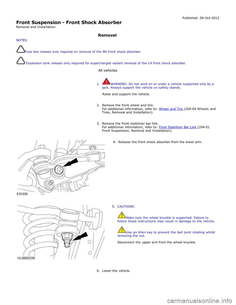
4. Release the front shock absorber from the lower arm.
5. CAUTIONS:
Make sure the wheel knuckle is supported. Failure to
follow these instructions may result in damage to the vehicle.
Use an Allen key to prevent the ball joint rotating whilst
removing the nut.
Disconnect the upper arm from the wheel knuckle.
6. Lower the vehicle.
Page 341 of 3039

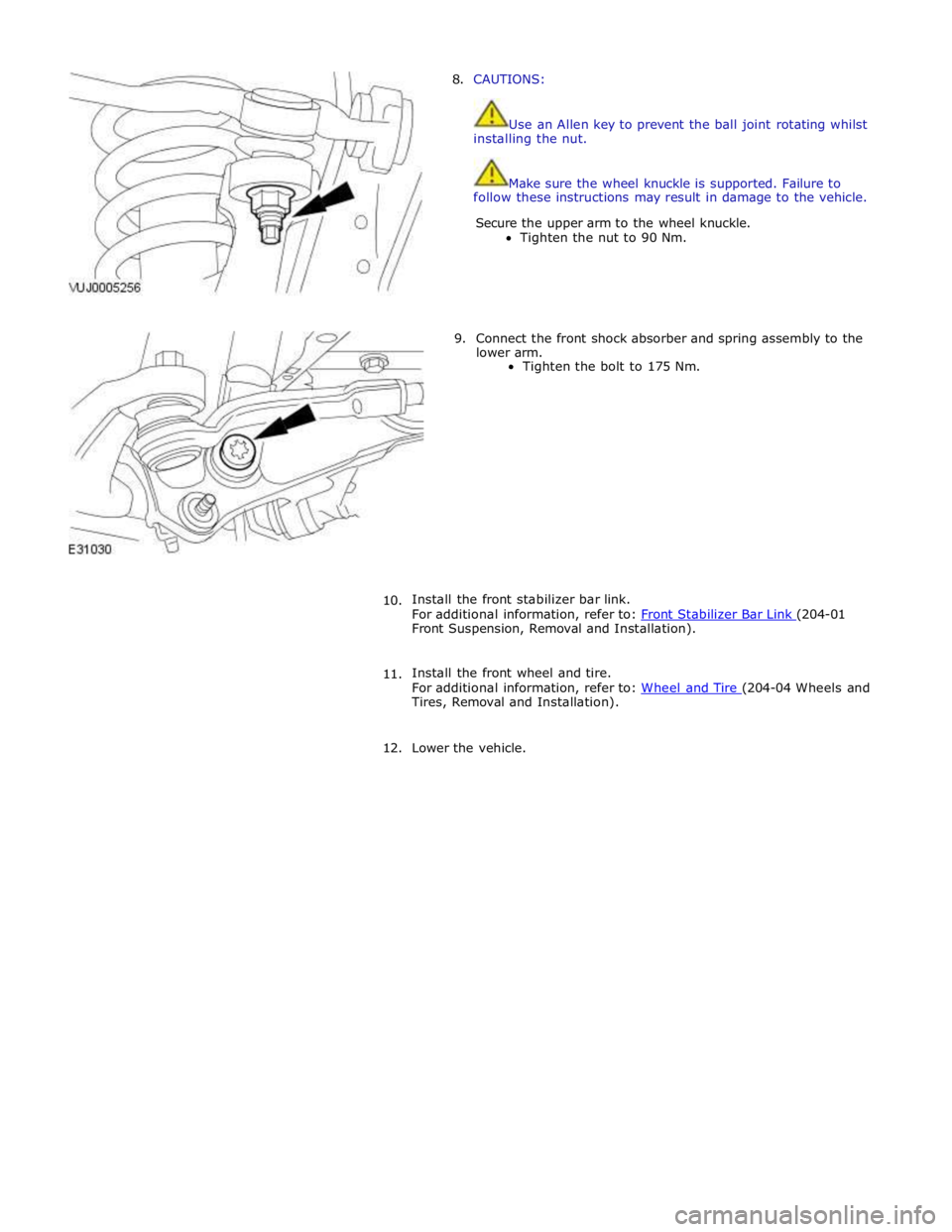
8. CAUTIONS:
Use an Allen key to prevent the ball joint rotating whilst
installing the nut.
Make sure the wheel knuckle is supported. Failure to
follow these instructions may result in damage to the vehicle.
Secure the upper arm to the wheel knuckle.
Tighten the nut to 90 Nm.
9. Connect the front shock absorber and spring assembly to the
lower arm.
Tighten the bolt to 175 Nm.
10. Install the front stabilizer bar link.
For additional information, refer to: Front Stabilizer Bar Link (204-01 Front Suspension, Removal and Installation).
11. Install the front wheel and tire.
For additional information, refer to: Wheel and Tire (204-04 Wheels and Tires, Removal and Installation).
12. Lower the vehicle.
Page 536 of 3039

60 Oil seal The multi-plate clutch is contained in a clutch basket attached to the differential carrier with the crown wheel securing bolts.
Alternate plates of the clutch pack are keyed to the clutch basket and the LH sun gear. A pressure disc is installed on the outer end of the clutch pack and keyed to the clutch basket. A thrust race on the end of the clutch basket incorporates lugs which
extend through the clutch basket onto the pressure disc.
The actuator assembly is mounted on bearings on the outboard end of the clutch basket, against the thrust race. The actuator
assembly consists of input and output actuators separated by five ball bearings. A locking pin in the cover engages with a slot
in the output actuator to prevent it turning, but allow it to move axially. The input actuator engages with the reduction gearbox
and is free to rotate relative to the cover. Ball bearings locate in curved grooves in the mating faces of the input and
output actuators. The bottom surface of each groove incorporates a ramp. Rotation of the input actuator forces the ball
bearings up the ramps in the grooves and induces an axial movement in the output actuator. The thrust race and pressure disc
transfer the axial movement from the output actuator to the clutch pack.
Item Description 1 Actuator 2 Multi-plate clutch 3 Differential The motor is a 12 V dc motor that adjusts the frictional loading of the multi-plate clutch, via the reduction gearbox and the
actuator assembly, under the control of the DLM. Adjusting the frictional loading of the multi-plate clutch adjusts the locking
torque between the crown wheel drive gear and the sun wheel.
Four bolts attach the motor to the reduction gearbox, which is located in position on the cover with two dowels, and secured
with four bolts. An O-ring seals the joint between the motor and the reduction gearbox.
The motor is driven by a 12 V dc feed direct from the DLM. The motor also incorporates the following connections with the
DLM:
A motor temperature sensor, to prevent excessive use from damaging the motor.
Two Hall effect motor position sensors, to enable closed loop control of the motor.
The temperature sensor provides a differential oil temperature signal to the DLM, to prevent excessive use from damaging the
multi-plate clutch.
Differential Locking Module (DLM)
The DLM controls operation of the electronic differential. The DLM is attached to a bracket located on the LH side of the luggage compartment, immediately forward of the fender tail lamp, behind the trim.
Page 727 of 3039

between moving components such as the steering wheel to steering column shroud.
Grunt (Squawk/Whoop)
Grunt is a 'honking' sound elicited when coming off one of the steering stops. Grunt is generally excited during parking
manoeuvres with a low to medium speed steering input.
Hiss (Swish)
Hiss or Valve Hiss is a high-frequency sound coming from the steering gear when the system is loaded. It is a rushing or
'swish' noise that doesn't change frequency with RPM. Hiss is the general noise generated by the flow of hydraulic fluid through
restrictions in the steering system. Restrictions include the rotary steering valve, power steering tubes, connectors, tuning
orifices, etc. Hiss can be air-borne and structure-borne, but the structure-borne path through the steering intermediate shaft is
usually dominant.
Moan (Groan)
Moan is the general structure-borne noise of the steering system. Moan is primarily transmitted to the driver via the body
structure through the pump mount, engine mounts, power steering lines and power steering brackets. On some vehicles, moan
is a loud humming noise, often present when the wheel is turned and the system is loaded. It may change frequency with
engine RPM and if the system is loaded or unloaded.
Steering Gear Knock (Steering Gear Slap)
CAUTION: DO NOT attempt to adjust the steering gear yoke. Failure to follow this instruction will invalidate the steering
gear warranty.
Steering gear knock is a rattle sound and steering wheel vibration caused by separation of the steering gear and pinion while
driving over bumps. It is a structure-borne noise transmitted through the intermediate shaft and column. Steering gear knock
can also be heard as a 'thump' or impact noise that occurs with the vehicle stationary when the steering wheel is released
from a loaded position and allowed to return to rest. Noise occurs with the engine on or off.
Rattles
Rattles are noises caused by knocking or hitting of components in the steering system. Steering rattles can occur in the engine
compartment, the suspension, or the passenger compartment. Rattles can be caused by loose components, movable and
flexible components, and improper clearances.
Squeaks/Scrapes
Squeaks/Scrapes are noises due to friction or component rubbing anywhere in the steering system. Squeaks/Scrapes have
appeared in steering linkages and joints, in column components and in column and steering wheel trim.
Weep
Weep is an air-borne noise, occasionally generated when turning the steering across lock at a constant rate. When present on
a vehicle the noise, once initiated can often be maintained across a large proportion of the available steering movement.
Whistle
Whistle is similar to hiss but is louder and of a higher frequency. It is also more of a pure tone noise than hiss. Whistle is
air-borne and is generated by a high flow rate of hydraulic fluid through a small restriction.
Zip
Zip noise is the air-borne noise generated by power steering pump cavitation when power steering fluid does not flow freely
through the suction hose from the reservoir to the pump. Zip primarily occurs during cold weather at start-up.
Steering System Vibrations and Harshness
Buzz
Buzz is a tactile rotary vibration felt in the steering wheel when steering inputs are slow. Buzz can also be called a grinding
feel and it is closely related to grunt and is caused by high system gain with low damping. Buzz is generally excited during
parking manoeuvres with low to medium speed steering input.
Buzz (Electrical)
A different steering buzz can be caused by pulse width modulated (PWM) electric actuators used in variable assist steering
systems. This buzz is felt by turning the ignition key to run without starting the engine and holding onto the steering wheel.
In extreme cases, the buzz can be felt with the engine running also.
Column/Steering Wheel Shake
Column shake is a low frequency vertical vibration excited by primary engine vibrations.
Nibble (Shimmy)
Page 753 of 3039

Power Steering - Steering Gear
Removal and Installation Published: 04-Jul-2013
CAUTIONS: Removal
Make sure that only the manufacturers' recommended four wheel alignment equipment is used.
Do not turn the steering wheel with the steering column lower shaft disconnected as damage to the clockspring and
steering wheel switches may occur.
NOTES:
Make sure the steering is in the straight ahead position.
RHD illustration shown, LHD is similar.
Some variation in the illustrations may occur, but the essential information is always correct.
1. Raise and support the vehicle.
2. Center the steering wheel.
Lock in position and remove the ignition key.
3. Remove the front wheels and tires.
For additional information, refer to: Wheel and Tire (204-04 Wheels and Tires, Removal and Installation).
4. Remove the air deflector.
For additional information, refer to: Air Deflector (501-02 Front End Body Panels, Removal and Installation).
Page 1034 of 3039

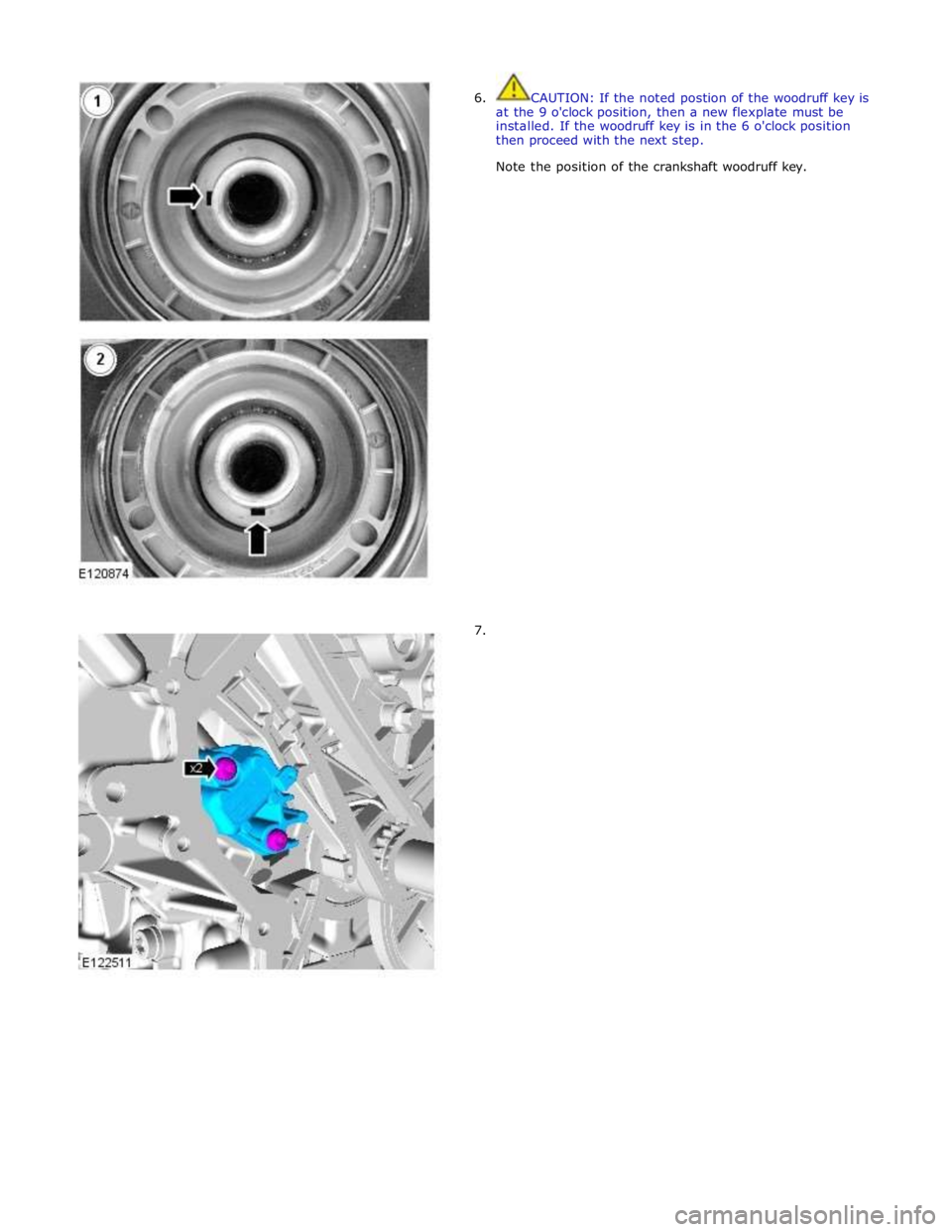
6. CAUTION: If the noted postion of the woodruff key is
at the 9 o'clock position, then a new flexplate must be
installed. If the woodruff key is in the 6 o'clock position
then proceed with the next step.
Note the position of the crankshaft woodruff key.
7.
Page 1041 of 3039

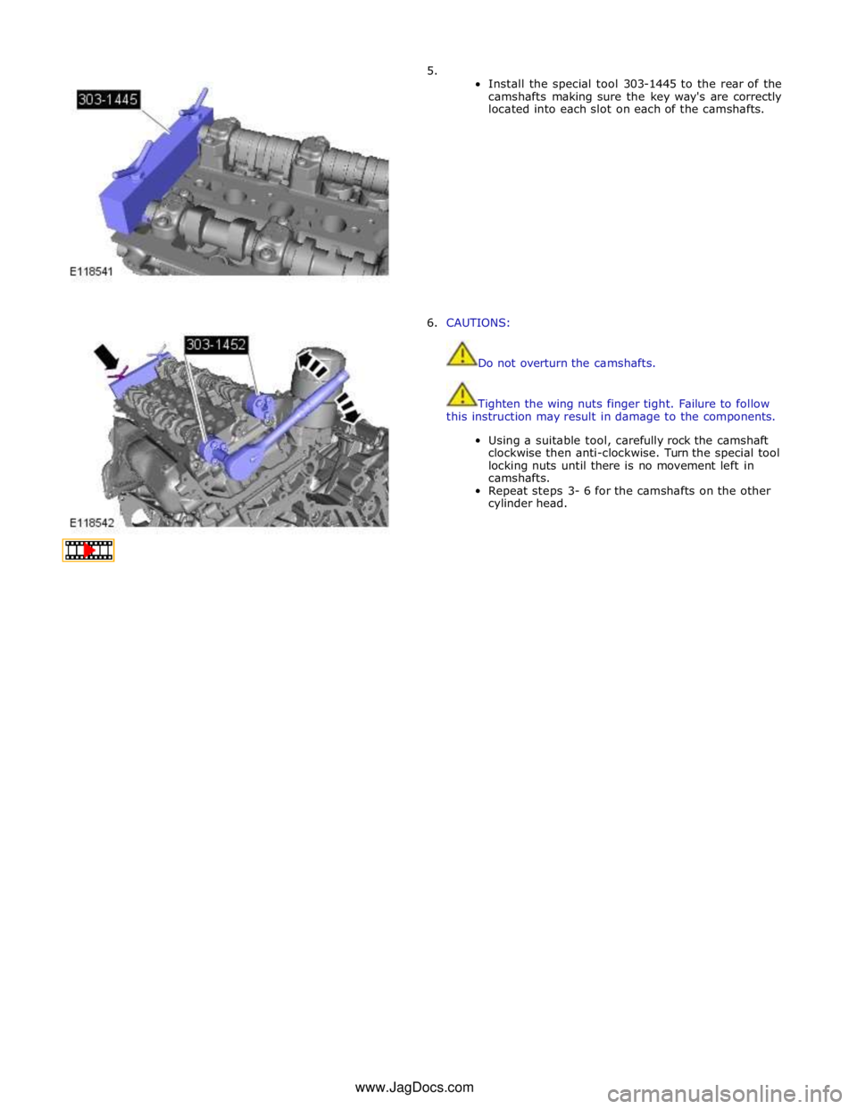
5.
Install the special tool 303-1445 to the rear of the
camshafts making sure the key way's are correctly
located into each slot on each of the camshafts.
6. CAUTIONS:
Do not overturn the camshafts.
Tighten the wing nuts finger tight. Failure to follow
this instruction may result in damage to the components.
Using a suitable tool, carefully rock the camshaft
clockwise then anti-clockwise. Turn the special tool
locking nuts until there is no movement left in
camshafts.
Repeat steps 3- 6 for the camshafts on the other
cylinder head. www.JagDocs.com