2010 JAGUAR XFR lock
[x] Cancel search: lockPage 1823 of 3039
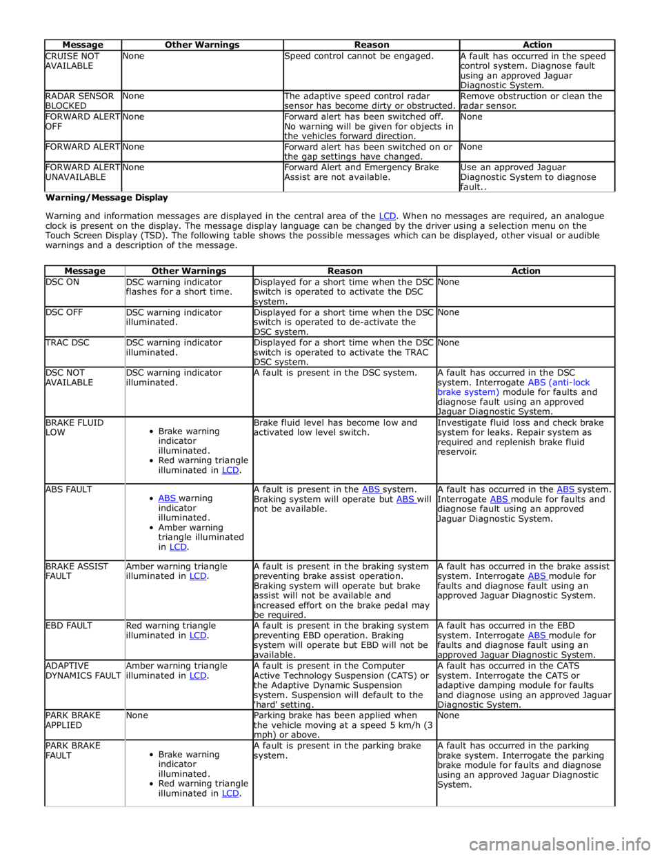
Message Other Warnings Reason Action CRUISE NOT
AVAILABLE None Speed control cannot be engaged.
A fault has occurred in the speed
control system. Diagnose fault
using an approved Jaguar Diagnostic System. RADAR SENSOR
BLOCKED None
The adaptive speed control radar
sensor has become dirty or obstructed. Remove obstruction or clean the
radar sensor. FORWARD ALERT
OFF None
Forward alert has been switched off.
No warning will be given for objects in
the vehicles forward direction. None FORWARD ALERT None
Forward alert has been switched on or
the gap settings have changed. None FORWARD ALERT
UNAVAILABLE None
Forward Alert and Emergency Brake
Assist are not available. Use an approved Jaguar
Diagnostic System to diagnose
fault.. Warning/Message Display
Warning and information messages are displayed in the central area of the LCD. When no messages are required, an analogue clock is present on the display. The message display language can be changed by the driver using a selection menu on the
Touch Screen Display (TSD). The following table shows the possible messages which can be displayed, other visual or audible
warnings and a description of the message.
Message Other Warnings Reason Action DSC ON
DSC warning indicator
flashes for a short time. Displayed for a short time when the DSC
switch is operated to activate the DSC system. None DSC OFF
DSC warning indicator
illuminated. Displayed for a short time when the DSC
switch is operated to de-activate the
DSC system. None TRAC DSC
DSC warning indicator
illuminated. Displayed for a short time when the DSC
switch is operated to activate the TRAC
DSC system. None DSC NOT
AVAILABLE DSC warning indicator
illuminated. A fault is present in the DSC system.
A fault has occurred in the DSC
system. Interrogate ABS (anti-lock
brake system) module for faults and
diagnose fault using an approved Jaguar Diagnostic System. BRAKE FLUID
LOW
Brake warning
indicator
illuminated.
Red warning triangle
illuminated in LCD. Brake fluid level has become low and
activated low level switch. Investigate fluid loss and check brake
system for leaks. Repair system as
required and replenish brake fluid
reservoir. ABS FAULT
ABS warning indicator
illuminated.
Amber warning
triangle illuminated
in LCD. A fault is present in the ABS system. Braking system will operate but ABS will not be available. A fault has occurred in the ABS system. Interrogate ABS module for faults and diagnose fault using an approved
Jaguar Diagnostic System. BRAKE ASSIST
FAULT Amber warning triangle
illuminated in LCD. A fault is present in the braking system
preventing brake assist operation.
Braking system will operate but brake
assist will not be available and
increased effort on the brake pedal may
be required. A fault has occurred in the brake assist
system. Interrogate ABS module for faults and diagnose fault using an
approved Jaguar Diagnostic System. EBD FAULT
Red warning triangle
illuminated in LCD. A fault is present in the braking system
preventing EBD operation. Braking
system will operate but EBD will not be
available. A fault has occurred in the EBD
system. Interrogate ABS module for faults and diagnose fault using an approved Jaguar Diagnostic System. ADAPTIVE
DYNAMICS FAULT Amber warning triangle
illuminated in LCD. A fault is present in the Computer
Active Technology Suspension (CATS) or
the Adaptive Dynamic Suspension
system. Suspension will default to the
'hard' setting. A fault has occurred in the CATS
system. Interrogate the CATS or
adaptive damping module for faults
and diagnose using an approved Jaguar Diagnostic System. PARK BRAKE
APPLIED None
Parking brake has been applied when
the vehicle moving at a speed 5 km/h (3 mph) or above. None PARK BRAKE
FAULT
Brake warning
indicator
illuminated.
Red warning triangle
illuminated in LCD. A fault is present in the parking brake
system. A fault has occurred in the parking
brake system. Interrogate the parking
brake module for faults and diagnose
using an approved Jaguar Diagnostic
System.
Page 1825 of 3039
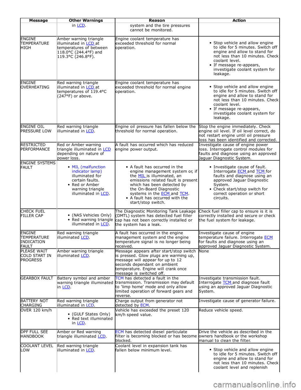
Message Other Warnings Reason Action in LCD. system and the tire pressures
cannot be monitored. ENGINE TEMPERATURE
HIGH Amber warning triangle
illuminated in LCD at temperatures of between
118.0°C (244.4°F) and
119.3°C (246.8°F). Engine coolant temperature has
exceeded threshold for normal
operation.
Stop vehicle and allow engine
to idle for 5 minutes. Switch off
engine and allow to stand for
not less than 10 minutes. Check
coolant level.
If message re-appears,
investigate coolant system for
leakage. ENGINE
OVERHEATING Red warning triangle
illuminated in LCD at temperatures of 119.4°C
(247°F) or above. Engine coolant temperature has
exceeded threshold for normal engine
operation.
Stop vehicle and allow engine
to idle for 5 minutes. Switch off
engine and allow to stand for
not less than 10 minutes. Check
coolant level.
If message re-appears,
investigate coolant system for
leakage. ENGINE OIL
PRESSURE LOW Red warning triangle
illuminated in LCD. Engine oil pressure has fallen below the
threshold for normal operation. Stop the engine immediately. Check
engine oil level. If oil level correct, do
not restart engine until oil pressure
loss has been identified and corrected. RESTRICTED
PERFORMANCE Red or Amber warning
triangle illuminated in LCD depending on nature of power loss. A fault has occurred which has reduced
engine power output. Investigate cause of engine power
loss. Interrogate control modules for
faults and diagnose using an approved Jaguar Diagnostic System. ENGINE SYSTEMS
FAULT
MIL (malfunction
indicator lamp)
illuminated for
certain faults.
Red or Amber
warning triangle
illuminated in LCD.
A fault has occurred in the
engine management system or, if
the MIL is illuminated, an emissions related fault is present
which has been detected by
the On-Board Diagnostic
systems in the ECM and TCM. A fault has occurred with the
start/stop switch.
Investigate cause of fault.
Interrogate ECM and TCM for faults and diagnose using an
approved Jaguar Diagnostic
System.
Check start/stop switch for
correct operation or short
circuits. CHECK FUEL
FILLER CAP
(NAS Vehicles Only)
Red warning triangle
illuminated in LCD. The Diagnostic Monitoring Tank Leakage
(DMTL) system has detected fuel filler
cap has not been correctly installed or
the system has a leak. Check fuel filler cap to ensure is it is
correctly installed and secure or check
the fuel system for leakage. ENGINE TEMPERATURE
INDICATION
FAULT Red warning triangle
illuminated LCD. A fault has occurred in the engine
management system and the engine
temperature signal is no longer being
received. Investigate cause of engine
temperature failure. Interrogate ECM for faults and diagnose using an approved Jaguar Diagnostic System. PLEASE WAIT
COLD START IN
PROGRESS Amber warning triangle
illuminated LCD. Message appears after start/stop switch
is pressed. Glow plugs are warming up,
message will appear for up to 12
seconds dependant on ambient
temperature. Engine will crank once message is switched off. None GEARBOX FAULT
Battery symbol and amber
warning triangle illuminated
in LCD. TCM has detected a fault in the Investigate transmission fault. transmission. Transmission may default
to 'limp home' mode and only allow
limited operation of forward gears and
reverse. Interrogate TCM and diagnose fault using an approved Jaguar Diagnostic
System. BATTERY NOT
CHARGING Red warning triangle
illuminated in LCD. Charge output from generator not
detected by ECM. Investigate cause of generator failure. OVER 120 km/h
(GULF States Only)
Red text illuminated
in LCD. Vehicle has exceeded the preset 120
km/h speed value. Reduce vehicle speed. DPF FULL SEE
HANDBOOK Amber or Red warning
triangle illuminated LCD. ECM has detected diesel particulate Drive the vehicle as described in the filter is becoming blocked or has become
blocked. owners handbook or the workshop
manual to clean the filter. COOLANT LEVEL
LOW Red warning triangle
illuminated in LCD. Coolant level in expansion tank has
fallen below minimum level.
Stop vehicle and allow engine
to idle for 5 minutes. Switch off
engine and allow to stand for
not less than 10 minutes. Check
coolant level and replenish
Page 1826 of 3039
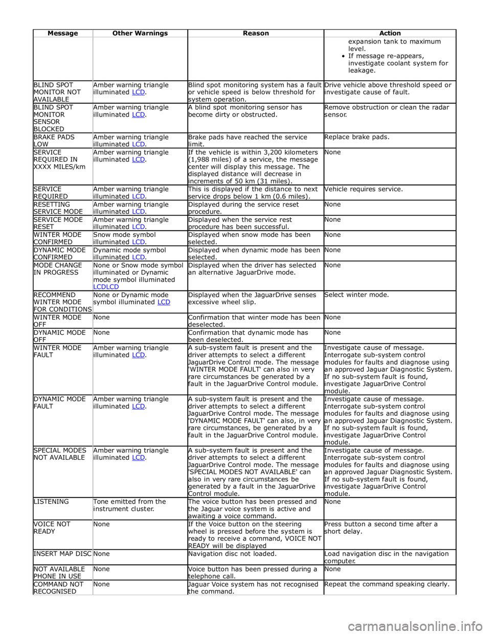
Message Other Warnings Reason Action expansion tank to maximum
level.
If message re-appears,
investigate coolant system for
leakage. BLIND SPOT
MONITOR NOT
AVAILABLE Amber warning triangle
illuminated LCD. Blind spot monitoring system has a fault
or vehicle speed is below threshold for system operation. Drive vehicle above threshold speed or
investigate cause of fault. BLIND SPOT
MONITOR
SENSOR
BLOCKED Amber warning triangle
illuminated LCD. A blind spot monitoring sensor has
become dirty or obstructed. Remove obstruction or clean the radar
sensor. BRAKE PADS
LOW Amber warning triangle
illuminated LCD. Brake pads have reached the service
limit. Replace brake pads. SERVICE
REQUIRED IN
XXXX MILES/km Amber warning triangle
illuminated LCD. If the vehicle is within 3,200 kilometers
(1,988 miles) of a service, the message
center will display this message. The
displayed distance will decrease in
increments of 50 km (31 miles). None SERVICE
REQUIRED Amber warning triangle
illuminated LCD. This is displayed if the distance to next
service drops below 1 km (0.6 miles). Vehicle requires service. RESETTING
SERVICE MODE Amber warning triangle
illuminated LCD. Displayed during the service reset procedure. None SERVICE MODE
RESET Amber warning triangle
illuminated LCD. Displayed when the service rest procedure has been successful. None WINTER MODE
CONFIRMED Snow mode symbol
illuminated LCD. Displayed when snow mode has been
selected. None DYNAMIC MODE
CONFIRMED Dynamic mode symbol
illuminated LCD. Displayed when dynamic mode has been
selected. None MODE CHANGE
IN PROGRESS None or Snow mode symbol
illuminated or Dynamic
mode symbol illuminated
LCDLCD Displayed when the driver has selected
an alternative JaguarDrive mode. None RECOMMEND
WINTER MODE
FOR CONDITIONS None or Dynamic mode
symbol illuminated LCD Displayed when the JaguarDrive senses
excessive wheel slip. Select winter mode. WINTER MODE
OFF None
Confirmation that winter mode has been
deselected. None DYNAMIC MODE
OFF None
Confirmation that dynamic mode has
been deselected. None WINTER MODE
FAULT Amber warning triangle
illuminated LCD. A sub-system fault is present and the
driver attempts to select a different
JaguarDrive Control mode. The message
'WINTER MODE FAULT' can also in very
rare circumstances be generated by a
fault in the JaguarDrive Control module. Investigate cause of message.
Interrogate sub-system control
modules for faults and diagnose using
an approved Jaguar Diagnostic System.
If no sub-system fault is found,
investigate JaguarDrive Control
module. DYNAMIC MODE
FAULT Amber warning triangle
illuminated LCD. A sub-system fault is present and the
driver attempts to select a different
JaguarDrive Control mode. The message
'DYNAMIC MODE FAULT' can also, in very
rare circumstances, be generated by a
fault in the JaguarDrive Control module. Investigate cause of message.
Interrogate sub-system control
modules for faults and diagnose using
an approved Jaguar Diagnostic System.
If no sub-system fault is found,
investigate JaguarDrive Control
module. SPECIAL MODES
NOT AVAILABLE Amber warning triangle
illuminated LCD. A sub-system fault is present and the
driver attempts to select a different
JaguarDrive Control mode. The message
'SPECIAL MODES NOT AVAILABLE' can
also in very rare circumstances be
generated by a fault in the JaguarDrive
Control module. Investigate cause of message.
Interrogate sub-system control
modules for faults and diagnose using
an approved Jaguar Diagnostic System.
If no sub-system fault is found,
investigate JaguarDrive Control
module. LISTENING Tone emitted from the
instrument cluster. The voice button has been pressed and
the Jaguar voice system is active and awaiting a voice command. None VOICE NOT
READY None
If the Voice button on the steering
wheel is pressed before the system is
ready to receive a command, VOICE NOT
READY will be displayed Press button a second time after a
short delay. INSERT MAP DISC None Navigation disc not loaded.
Load navigation disc in the navigation
computer. NOT AVAILABLE
PHONE IN USE None
Voice button has been pressed during a telephone call. None COMMAND NOT
RECOGNISED None
Jaguar Voice system has not recognised
the command. Repeat the command speaking clearly.
Page 1828 of 3039
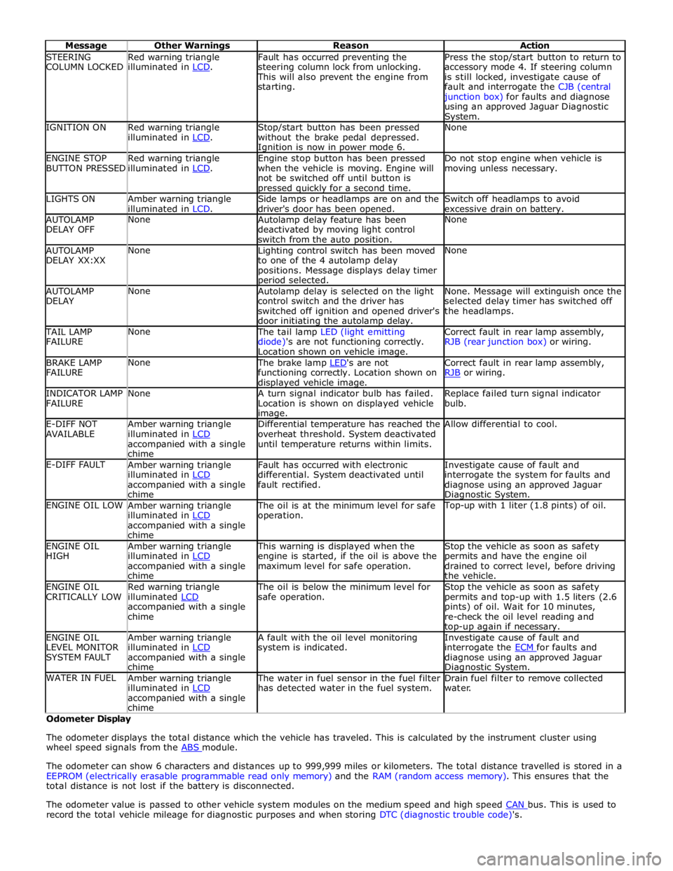
STEERING
COLUMN LOCKED Red warning triangle
illuminated in LCD. Fault has occurred preventing the
steering column lock from unlocking. This will also prevent the engine from
starting. Press the stop/start button to return to
accessory mode 4. If steering column
is still locked, investigate cause of
fault and interrogate the CJB (central junction box) for faults and diagnose
using an approved Jaguar Diagnostic System. IGNITION ON
Red warning triangle
illuminated in LCD. Stop/start button has been pressed
without the brake pedal depressed. Ignition is now in power mode 6. None ENGINE STOP
BUTTON PRESSED Red warning triangle
illuminated in LCD. Engine stop button has been pressed
when the vehicle is moving. Engine will
not be switched off until button is pressed quickly for a second time. Do not stop engine when vehicle is
moving unless necessary. LIGHTS ON
Amber warning triangle
illuminated in LCD. Side lamps or headlamps are on and the
driver's door has been opened. Switch off headlamps to avoid
excessive drain on battery. AUTOLAMP
DELAY OFF None
Autolamp delay feature has been
deactivated by moving light control
switch from the auto position. None AUTOLAMP
DELAY XX:XX None
Lighting control switch has been moved
to one of the 4 autolamp delay
positions. Message displays delay timer period selected. None AUTOLAMP
DELAY None
Autolamp delay is selected on the light
control switch and the driver has
switched off ignition and opened driver's
door initiating the autolamp delay. None. Message will extinguish once the
selected delay timer has switched off
the headlamps. TAIL LAMP
FAILURE None The tail lamp LED (light emitting
diode)'s are not functioning correctly.
Location shown on vehicle image. Correct fault in rear lamp assembly,
RJB (rear junction box) or wiring. BRAKE LAMP
FAILURE None The brake lamp LED's are not functioning correctly. Location shown on displayed vehicle image. Correct fault in rear lamp assembly,
RJB or wiring. INDICATOR LAMP
FAILURE None
A turn signal indicator bulb has failed.
Location is shown on displayed vehicle image. Replace failed turn signal indicator
bulb. E-DIFF NOT
AVAILABLE Amber warning triangle
illuminated in LCD accompanied with a single
chime Differential temperature has reached the
overheat threshold. System deactivated
until temperature returns within limits. Allow differential to cool. E-DIFF FAULT
Amber warning triangle
illuminated in LCD accompanied with a single
chime Fault has occurred with electronic
differential. System deactivated until
fault rectified. Investigate cause of fault and
interrogate the system for faults and
diagnose using an approved Jaguar Diagnostic System. ENGINE OIL LOW
Amber warning triangle
illuminated in LCD accompanied with a single
chime The oil is at the minimum level for safe
operation. Top-up with 1 liter (1.8 pints) of oil. ENGINE OIL
HIGH Amber warning triangle
illuminated in LCD accompanied with a single
chime This warning is displayed when the
engine is started, if the oil is above the
maximum level for safe operation. Stop the vehicle as soon as safety
permits and have the engine oil
drained to correct level, before driving
the vehicle. ENGINE OIL
CRITICALLY LOW Red warning triangle
illuminated LCD accompanied with a single
chime The oil is below the minimum level for
safe operation. Stop the vehicle as soon as safety
permits and top-up with 1.5 liters (2.6
pints) of oil. Wait for 10 minutes,
re-check the oil level reading and top-up again if necessary. ENGINE OIL
LEVEL MONITOR
SYSTEM FAULT Amber warning triangle
illuminated in LCD accompanied with a single
chime A fault with the oil level monitoring
system is indicated. Investigate cause of fault and
interrogate the ECM for faults and diagnose using an approved Jaguar Diagnostic System. WATER IN FUEL
Amber warning triangle
illuminated in LCD accompanied with a single
chime The water in fuel sensor in the fuel filter
has detected water in the fuel system. Drain fuel filter to remove collected
water. Odometer Display
The odometer displays the total distance which the vehicle has traveled. This is calculated by the instrument cluster using
wheel speed signals from the ABS module.
The odometer can show 6 characters and distances up to 999,999 miles or kilometers. The total distance travelled is stored in a
EEPROM (electrically erasable programmable read only memory) and the RAM (random access memory). This ensures that the
total distance is not lost if the battery is disconnected.
The odometer value is passed to other vehicle system modules on the medium speed and high speed CAN bus. This is used to record the total vehicle mileage for diagnostic purposes and when storing DTC (diagnostic trouble code)'s.
Page 1832 of 3039
Warning Devices - Blindspot Monitoring System - Overview
Description and Operation
OVERVIEW Published: 11-May-2011
Eliminating blind spots is a major element in vehicle body design, but because of the structural requirements of B, C and D
posts, blind spots cannot be entirely eliminated. Statistics show that some accidents are directly attributable to drivers moving
across into the path of overtaking vehicles that have not been seen in conventional mirrors. New mirror designs have improved
the situation, but by remotely covering areas that cannot be seen either directly or by the vehicle mirrors, have led to the
introduction of a radar-based blind spot monitoring system.
The blind spot monitoring system comprises:
LH (left-hand) Blind spot monitoring sensor
RH (right-hand) Blind spot monitoring sensor
LH door mirror RH door mirror
The system uses two radar modules operating at a frequency of 24 GHz and each combining the radar face and electronic
module in a single unit. The modules are located behind the rear bumper surface, symmetrically, one on each side of the car
behind the rear wheels. They are side facing and inclined rearwards at an angle of 16 degrees, which is dictated by the shape
at the rear of the vehicle. Each module is calibrated to detect a vehicle in the driver’s blind spot. Once a vehicle is detected
the module illuminates an amber warning ‘alert icon’ LED (light emitting diode) in the relevant exterior door mirror. If there is a
fault or blockage with the blind spot monitoring system an amber warning indicator dot LED is displayed in the exterior mirror and the message ‘blind spot monitoring not available’ is displayed in the instrument cluster message center.
When the system initiates, it performs a self-check, during which the warning icons in the mirrors illuminate alternately for a
short period of time. Each module does a left/right determination check when the ignition is switched on. Each mirror has a
different circuit configuration so that the modules can determine which mirror they are connected to. If a module detects the
wrong mirror it will go into a fault condition.
The blind spot monitoring modules receive vehicle speed on the medium speed CAN (controller area network) and are inactive
until the vehicle reaches 16kph (10mph). Each blind spot monitor module emits a radar field greater than the blind spot area.
Each Blind Spot Monitor module emits a radar field greater than the blind spot area. The actual blind spot area is calibrated
into the module during its manufacture.
CAUTION: The blind spot monitoring system is designed as a driver aid not a safety device. The driver should always
exercise due care and attention whilst driving. www.JagDocs.com
Page 1834 of 3039
Blind Spot Monitoring System Operation
The purpose of the blind spot monitoring system is to detect an object moving with a positive velocity relative to the radar
module, on either side of the vehicle, at a distance of up to 2.5 meters laterally and in an area from the door mirror up to 7.0
meters behind the module. These criteria identify an overtaking vehicle within the blind-spot area and within a typical
carriageway lane width, while eliminating other objects that are not relevant, either because of their position, they are
stationary, traveling in the opposite direction, or being overtaken. A vehicle is classed as a heavy goods vehicle, car or
motorcycle. A motorcycle is defined as a minimum size of 2.0m long, 0.8m wide (widest point) and 1.1m high. The system is
not affected by the mass of the overtaking vehicle providing all identification criteria, including relative velocity of (16km/h -
10mph) or above, is met.
The system emits radar pulses and analyses the reflections, identifying anything that moves into the blind spot zone. Having
detected another vehicle in the defined blind spot zone it alerts the driver by illuminating the amber alert icon located in the
appropriate exterior mirror.
NOTE: If an overtaking vehicle is detected on both sides of the vehicle simultaneously, the warning alert icons in both
mirrors will illuminate.
The light lens is shaped so as to minimize the visibility to other drivers. The LED (light emitting diode)’s are located towards
the outside extremity of the mirror face, within the peripheral view of the driver but not in any area of the mirror where they
could obscure or distract from the image.
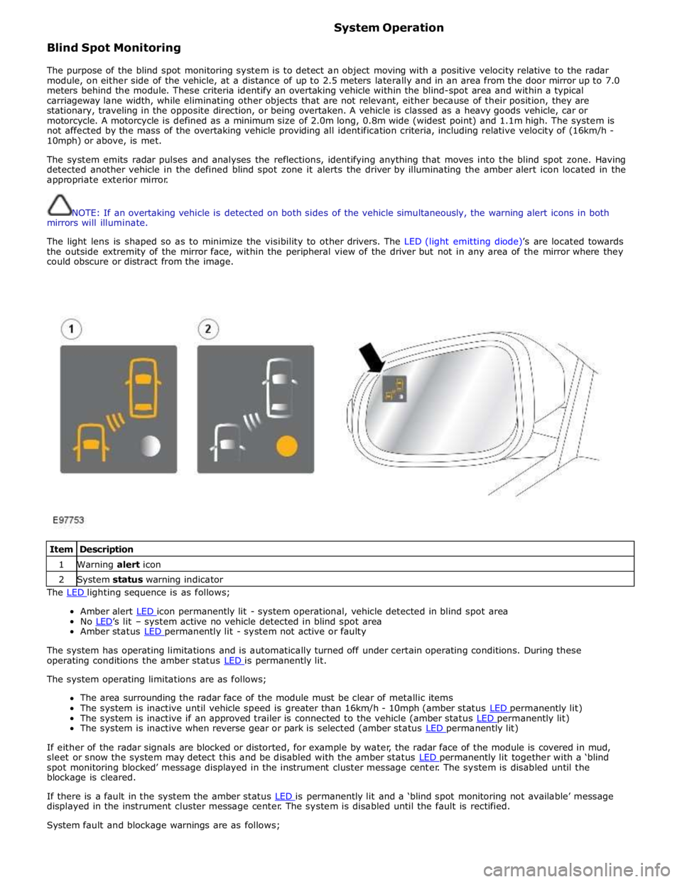
Item Description 1 Warning alert icon 2 System status warning indicator The LED lighting sequence is as follows;
Amber alert LED icon permanently lit - system operational, vehicle detected in blind spot area No LED’s lit – system active no vehicle detected in blind spot area Amber status LED permanently lit - system not active or faulty
The system has operating limitations and is automatically turned off under certain operating conditions. During these
operating conditions the amber status LED is permanently lit. The system operating limitations are as follows;
The area surrounding the radar face of the module must be clear of metallic items
The system is inactive until vehicle speed is greater than 16km/h - 10mph (amber status LED permanently lit) The system is inactive if an approved trailer is connected to the vehicle (amber status LED permanently lit) The system is inactive when reverse gear or park is selected (amber status LED permanently lit)
If either of the radar signals are blocked or distorted, for example by water, the radar face of the module is covered in mud,
sleet or snow the system may detect this and be disabled with the amber status LED permanently lit together with a ‘blind spot monitoring blocked’ message displayed in the instrument cluster message center. The system is disabled until the
blockage is cleared.
If there is a fault in the system the amber status LED is permanently lit and a ‘blind spot monitoring not available’ message displayed in the instrument cluster message center. The system is disabled until the fault is rectified.
System fault and blockage warnings are as follows;
Page 1839 of 3039
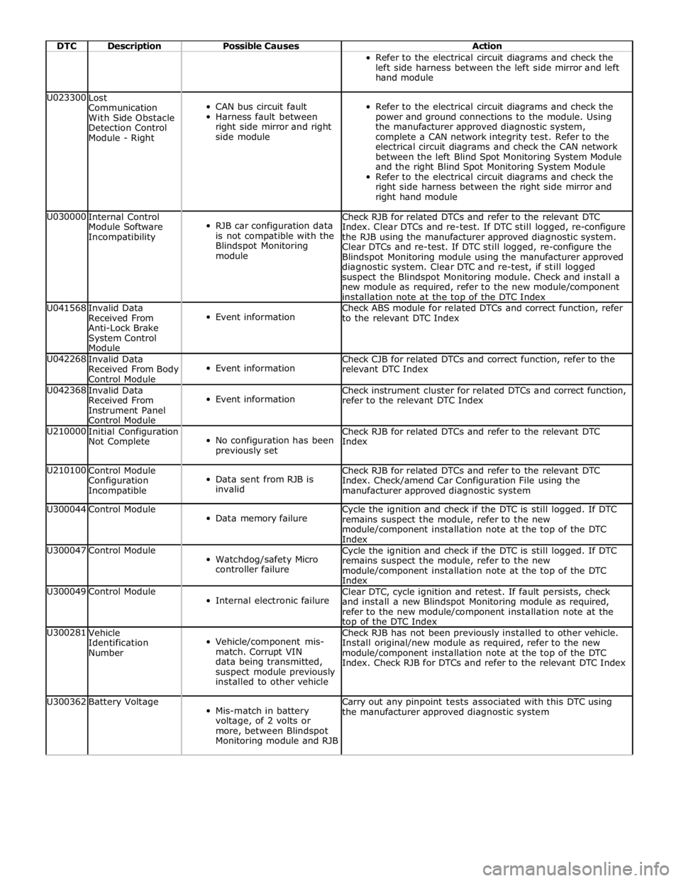
DTC Description Possible Causes Action Refer to the electrical circuit diagrams and check the
left side harness between the left side mirror and left
hand module U023300
Lost
Communication
With Side Obstacle
Detection Control
Module - Right
CAN bus circuit fault
Harness fault between
right side mirror and right
side module
Refer to the electrical circuit diagrams and check the
power and ground connections to the module. Using
the manufacturer approved diagnostic system,
complete a CAN network integrity test. Refer to the
electrical circuit diagrams and check the CAN network
between the left Blind Spot Monitoring System Module
and the right Blind Spot Monitoring System Module
Refer to the electrical circuit diagrams and check the
right side harness between the right side mirror and
right hand module U030000
Internal Control
Module Software
Incompatibility
RJB car configuration data
is not compatible with the
Blindspot Monitoring
module Check RJB for related DTCs and refer to the relevant DTC
Index. Clear DTCs and re-test. If DTC still logged, re-configure
the RJB using the manufacturer approved diagnostic system.
Clear DTCs and re-test. If DTC still logged, re-configure the
Blindspot Monitoring module using the manufacturer approved
diagnostic system. Clear DTC and re-test, if still logged
suspect the Blindspot Monitoring module. Check and install a
new module as required, refer to the new module/component
installation note at the top of the DTC Index U041568
Invalid Data
Received From
Anti-Lock Brake
System Control
Module
Event information Check ABS module for related DTCs and correct function, refer
to the relevant DTC Index U042268
Invalid Data
Received From Body
Control Module
Event information Check CJB for related DTCs and correct function, refer to the
relevant DTC Index U042368
Invalid Data
Received From
Instrument Panel
Control Module
Event information Check instrument cluster for related DTCs and correct function,
refer to the relevant DTC Index U210000
Initial Configuration
Not Complete
No configuration has been
previously set Check RJB for related DTCs and refer to the relevant DTC
Index U210100
Control Module
Configuration
Incompatible
Data sent from RJB is
invalid Check RJB for related DTCs and refer to the relevant DTC
Index. Check/amend Car Configuration File using the
manufacturer approved diagnostic system U300044 Control Module
Data memory failure Cycle the ignition and check if the DTC is still logged. If DTC
remains suspect the module, refer to the new
module/component installation note at the top of the DTC
Index U300047 Control Module
Watchdog/safety Micro
controller failure Cycle the ignition and check if the DTC is still logged. If DTC
remains suspect the module, refer to the new
module/component installation note at the top of the DTC
Index U300049 Control Module
Internal electronic failure Clear DTC, cycle ignition and retest. If fault persists, check
and install a new Blindspot Monitoring module as required,
refer to the new module/component installation note at the top of the DTC Index U300281
Vehicle
Identification
Number
Vehicle/component mis-
match. Corrupt VIN
data being transmitted,
suspect module previously
installed to other vehicle Check RJB has not been previously installed to other vehicle.
Install original/new module as required, refer to the new
module/component installation note at the top of the DTC
Index. Check RJB for DTCs and refer to the relevant DTC Index U300362 Battery Voltage
Mis-match in battery
voltage, of 2 volts or
more, between Blindspot
Monitoring module and RJB Carry out any pinpoint tests associated with this DTC using
the manufacturer approved diagnostic system
Page 1848 of 3039
information from other systems:
ABS (anti-lock brake system) module - Road speed signal
TCM (transmission control module) - Reverse gear engaged signal
Trailer module - Trailer attached to vehicle
The module also outputs messages on the medium speed CAN bus which are received by the integrated audio module. The integrated audio module processes these messages and converts them into Media Orientated System Transport (MOST) signals
which are passed to the audio system power amplifier. These signals are then used by the power amplifier to emit the
applicable warning tones from the front or rear audio speakers when an object is detected by the front or rear parking aid
sensors. A warning tone can also be emitted to alert the driver to a fault in the parking aid system.
The control module has a diagnostic connection via the medium speed CAN bus to enable faults to be retrieved using the
Jaguar approved diagnostic equipment. Additionally an on-board diagnostic routine within the control module constantly
monitors the system and alerts the driver to a system fault by emitting a 3 second continuous tone through the rear audio
system speakers when the ignition is switched on. If front parking aid sensors are fitted, the control switch LED will also flash
6 times.
Parking Aid Sensors
Four ultrasonic sensors are located in the front (if fitted) and rear bumpers.
Each sensor has a three pin connector which mates with a bumper harness, which in turn is connected to the main body
harness. Three pins provide for power supply, ground and signal lines to and from the parking aid module.
The parking aid module controls the operation of each sensor using a digital output on the signal line. The module controls the
sensor in one of two modes; combined transmitter and receiver mode or receiver mode only.
Parking Aid Switch
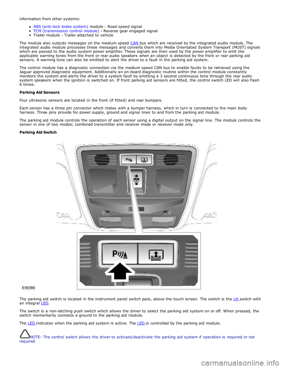
The parking aid switch is located in the instrument panel switch pack, above the touch screen. The switch is the LH switch with an integral LED.
The switch is a non-latching push switch which allows the driver to select the parking aid system on or off. When pressed, the
switch momentarily connects a ground to the parking aid module.
The LED indicates when the parking aid system is active. The LED is controlled by the parking aid module.
NOTE: The control switch allows the driver to activate/deactivate the parking aid system if operation is required or not
required.