2010 JAGUAR XFR lock
[x] Cancel search: lockPage 1647 of 3039
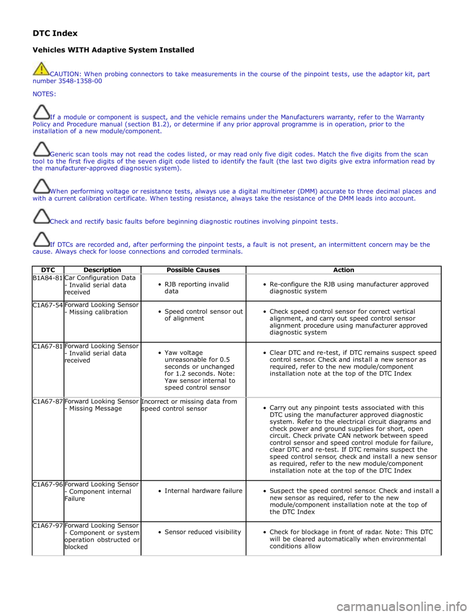
DTC Index
Vehicles WITH Adaptive System Installed
CAUTION: When probing connectors to take measurements in the course of the pinpoint tests, use the adaptor kit, part
number 3548-1358-00
NOTES:
If a module or component is suspect, and the vehicle remains under the Manufacturers warranty, refer to the Warranty
Policy and Procedure manual (section B1.2), or determine if any prior approval programme is in operation, prior to the
installation of a new module/component.
Generic scan tools may not read the codes listed, or may read only five digit codes. Match the five digits from the scan
tool to the first five digits of the seven digit code listed to identify the fault (the last two digits give extra information read by
the manufacturer-approved diagnostic system).
When performing voltage or resistance tests, always use a digital multimeter (DMM) accurate to three decimal places and
with a current calibration certificate. When testing resistance, always take the resistance of the DMM leads into account.
Check and rectify basic faults before beginning diagnostic routines involving pinpoint tests.
If DTCs are recorded and, after performing the pinpoint tests, a fault is not present, an intermittent concern may be the
cause. Always check for loose connections and corroded terminals.
DTC Description Possible Causes Action B1A84-81 Car Configuration Data
- Invalid serial data
received
RJB reporting invalid
data
Re-configure the RJB using manufacturer approved
diagnostic system C1A67-54 Forward Looking Sensor
- Missing calibration
Speed control sensor out
of alignment
Check speed control sensor for correct vertical
alignment, and carry out speed control sensor
alignment procedure using manufacturer approved
diagnostic system C1A67-81 Forward Looking Sensor
- Invalid serial data
received
Yaw voltage
unreasonable for 0.5
seconds or unchanged
for 1.2 seconds. Note:
Yaw sensor internal to
speed control sensor
Clear DTC and re-test, if DTC remains suspect speed
control sensor. Check and install a new sensor as
required, refer to the new module/component
installation note at the top of the DTC Index C1A67-87 Forward Looking Sensor
- Missing Message Incorrect or missing data from
speed control sensor
Carry out any pinpoint tests associated with this
DTC using the manufacturer approved diagnostic
system. Refer to the electrical circuit diagrams and
check power and ground supplies for short, open
circuit. Check private CAN network between speed
control sensor and speed control module for failure,
clear DTC and re-test. If DTC remains suspect the
speed control sensor, check and install a new sensor
as required, refer to the new module/component
installation note at the top of the DTC Index C1A67-96 Forward Looking Sensor
- Component internal
Failure
Internal hardware failure
Suspect the speed control sensor. Check and install a
new sensor as required, refer to the new
module/component installation note at the top of
the DTC Index C1A67-97 Forward Looking Sensor
- Component or system
operation obstructed or
blocked
Sensor reduced visibility
Check for blockage in front of radar. Note: This DTC
will be cleared automatically when environmental
conditions allow
Page 1648 of 3039

DTC Description Possible Causes Action C1A67-98 Forward Looking Sensor
- Component or system
over temperature
Speed control sensor
internal temperature
exceeded threshold
Allow system to cool. Note: This DTC will be cleared
automatically when environmental conditions allow P174E-81
Output Shaft
Speed/ABS Wheel
Speed Correlation -
Invalid serial data
received
Follow speed is
mis-calculated to too
high a value
Clear DTC and re-test U0001-88
High Speed CAN
Communication Bus -
Bus off
Vehicle CAN Bus off
condition
Carry out any pinpoint tests associated with this
DTC using the manufacturer approved diagnostic
system. Carry out CAN network integrity tests using
the manufacturer approved diagnostic system U0100-00
Lost Communications
With ECM/PCM "A" - No
sub type information
ECM missing message
Carry out any pinpoint tests associated with this
DTC using the manufacturer approved diagnostic
system. Check ECM for related DTCs and refer to the
relevant DTC Index U0101-00
Lost Communications
With TCM - No sub
type information
TCM missing message
Carry out any pinpoint tests associated with this
DTC using the manufacturer approved diagnostic
system. Check TCM for related DTCs and refer to the
relevant DTC Index U0103-00
Lost Communication
With Gear Shift Control
Module A - No sub type
information
No sub type information
Refer to the electrical circuit diagrams and check the
power and ground connections to the Transmission
Shift Module. Using the manufacturer approved
diagnostic system, complete a CAN network integrity
test. Refer to the electrical circuit diagrams and
check the CAN network between the Transmission
Shift Module and Speed Control Module U0103-87
Lost Communication
With Gear Shift Module
- Missing Message
Transmission shift
module missing message
Carry out any pinpoint tests associated with this
DTC using the manufacturer approved diagnostic
system. Check transmission shift module for related
DTCs and refer to the relevant DTC Index U0121-00
Lost Communication
With Anti-lock Brake
System (ABS) Control
Module - No sub type
information
ABS missing message
Carry out any pinpoint tests associated with this
DTC using the manufacturer approved diagnostic
system. Check ABS for related DTCs and refer to the
relevant DTC Index U0128-00
Lost Communications
With Park Brake Module
- No sub type
information
Parking brake missing
message
Carry out any pinpoint tests associated with this
DTC using the manufacturer approved diagnostic
system. Check parking brake module for related
DTCs and refer to the relevant DTC Index U0155-00
Lost Communications
With Instrument Panel
Cluster (IPC) Control
Module - No sub type
information
Instrument cluster
missing message
Carry out any pinpoint tests associated with this
DTC using the manufacturer approved diagnostic
system. Check instrument cluster for related DTCs
and refer to the relevant DTC Index U0300-00
Internal Control Module
Software
Incompatibility - No
sub type information
Invalid configuration
message is received
Re-configure the speed control module using the
manufacturer approved diagnostic system. Clear
DTCs and re-test. If DTC still logged, suspect
incorrect speed control module installed. Check and
install a new module as required, refer to new
module/component installation note at top of DTC
Index U0300-55
Internal Control Module
Software
Incompatibility - Not
configured
RJB - at least one of the
car configuration
parameters is not
configured
Re-configure the RJB using the manufacturer
approved diagnostic system www.JagDocs.com
Page 1649 of 3039

DTC Description Possible Causes Action U0401-00
Invalid Data Received
From ECM/PCM A - No
sub type information
ECM did not respond
properly to speed control
cancel or auto brake
cancel request
Check ECM for related DTCs and refer to relevant
DTC Index U0401-67
Invalid Data Received
From ECM/PCM A -
Signal incorrect after
event
ECM did not respond
properly to speed control
resume request
Check ECM for related DTCs and refer to relevant
DTC Index U0401-81
Invalid Data Received
From ECM/PCM A -
Invalid serial data
received
Invalid data received
from engine control
module
Bus signal/message
failure
Speed control inhibited
by ECM
Check the Engine Control Module for related DTCs
and refer to relevant DTC Index. If U040181 is
logged as historic but no other DTCs have logged in
the engine control module at the same time and
distance, it may be caused by cranking with low
voltage conditions. Check battery and charging
system according to instructions in the battery care
manual. Install the latest Engine Control Module
software using the manufacturer approved diagnostic
system, contact Dealer Technical Support before
replacing components U0415-53
Invalid Data Received
From Anti-Lock Braking
System (ABS) Control
Module - De-activated
Event information
Deactivated
Check the Anti-Lock Braking System Module for
related DTCs and refer to the relevant DTC index U0415-81
Invalid Data Received
From Anti-lock Brake
System (ABS) Control
Module - Invalid serial
data received
Stability assist fault
Check ABS module for related DTCs and refer to
relevant DTC Index U0417-67
Invalid Data Received
From Park Brake
Control Module - Signal
incorrect after event
Parking brake module did
not respond properly to
apply request
Check parking brake module for related DTCs and
refer to relevant DTC Index U0417-81
Invalid Data Received
From Park Brake
Control Module -
Invalid serial data
received
Speed control inhibited
by parking brake module
Check parking brake module for related DTCs and
refer to relevant DTC Index U0418-68
Invalid Data Received
From Brake System
Control Module - Event
information
Event information
Check the Anti-Lock Braking System Module for
related DTCs and refer to the relevant DTC index U0421-81
Invalid Data Received
From Suspension
Control Module 'A' -
Invalid serial data
received
Invalid serial data
received
Check the Suspension Control Module for related
DTCs and refer to the relevant DTC index U0423-81
Invalid Data Received
From Instrument Panel
Control Module -
Invalid serial data
received
Speed control inhibited
by instrument cluster
Check instrument cluster, CJB and RJB for related
DTCs and refer to relevant DTC Index U1A00-88
Private Communication
Network - Bus off
Bus off
The module setting this code has disabled CAN
transmission. Check for other bus off codes. Check
the module and circuits. Refer to the electrical circuit
diagrams. Clear all DTCs and road test the vehicle. If
the concern reoccurs contact Dealer Technical
Support for further advice. Under no circumstance
should any parts be replaced to overcome this issue U1A14-49
CAN Initialisation
Failure - Internal
electronic failure
Internal electronic failure
Suspect the speed control module. Check and install
a new module as required, refer to the new
module/component installation note at the top of
the DTC Index U2101-00
Control Module
Configuration
Incompatible - No sub
type information
Data sent from RJB is
invalid
Check/amend Car Configuration File using the
manufacturer approved diagnostic system, clear DTC
and re-test. If DTC remains, re-configure RJB using
manufacturer approved diagnostic system, clear DTC
and re-test. If DTC remains check RJB for DTCs and
Page 1651 of 3039

DTC Description Possible Causes Action for further assistance P0501-62
Vehicle Speed Sensor A
Range/Performance - Signal
compare failure
Vehicle speed - range
performance
Check ABS/TCM for related DTCs and refer
to relevant DTC Index P0504-00 Brake Switch A / B Correlation
- No sub type information
The brake pressure reading
does not agree with the
brake light switch value
Carry out any pinpoint tests associated with
this DTC using the manufacturer approved
diagnostic system. Refer to the electrical
circuit diagrams and check brake switch
circuits for short, open circuit, high
resistance P0504-01 Brake Switch A / B Correlation
- General electrical failure
Brake switch high fault:
- Brake lights stuck
on
- Gearshift interlock
inoperative
- Speed control
inoperative
Brake switch low fault:
- Brake lights
inoperative
- Gearshift stuck in
Park
- Reduced engine
braking
Carry out any pinpoint tests associated with
this DTC using the manufacturer approved
diagnostic system. Refer to the electrical
circuit diagrams and check brake switch
circuits for short, open circuit, high
resistance P0566-00
Cruise Control OFF Signal - No
sub type information
Speed control Cancel
switch 2 stuck closed
Refer to the electrical circuit diagrams and
check speed control switch circuits for short,
open circuit. Check for stuck switch. Check
and install a new speed control switch as
required P0567-00
Cruise Control DECREASE
DISTANCE Signal - No sub
type information
Speed control Resume
switch 7 stuck closed
Refer to the electrical circuit diagrams and
check speed control switch circuits for short,
open circuit. Check for stuck switch. Check
and install a new speed control switch as
required P0568-00
Cruise Control INCREASE
DISTANCE Signal - No sub
type information
Speed control Accel Set
Plus Switch 6 stuck closed
Check and install a new speed control
switch as required P0569-00
Cruise Control COAST Signal -
No sub type information
Speed control Coast Set
Minus switch 3 stuck
closed
Refer to the electrical circuit diagrams and
check speed control switch circuits for short,
open circuit. Check for stuck switch. Check
and install a new speed control switch as
required P056A-00
Cruise Control INCREASE
DISTANCE Signal - No sub
type information
Speed control Headway
Plus switch 4 stuck closed
Refer to the electrical circuit diagrams and
check speed control switch circuits for short,
open circuit. Check for stuck switch. Check
and install a new speed control switch as
required P056B-00
Cruise Control DECREASE
DISTANCE Signal - No sub
type information
Speed control Headway
Minus switch 5 stuck
closed
Refer to the electrical circuit diagrams and
check speed control switch circuits for short,
open circuit. Check for stuck switch. Check
and install a new speed control switch as
required P0571-62
Brake Switch A Circuit - Signal
compare failure
Plausibility error
Refer to the electrical circuit diagrams and
check brake light switch signal circuits for
short, open circuit. Check and install a new
brake light switch as required P0575-01
Cruise Control Input Circuit -
General electrical failure
General electrical failure
Check speed control system for related
DTCs and refer to relevant DTC Index. Carry
out CAN network integrity tests using the
Page 1654 of 3039
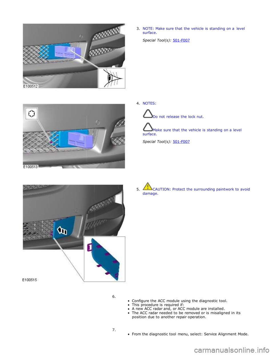
3. NOTE: Make sure that the vehicle is standing on a level
surface.
Special Tool(s): 501-F007
4. NOTES:
Do not release the lock nut.
Make sure that the vehicle is standing on a level
surface.
Special Tool(s): 501-F007
5. CAUTION: Protect the surrounding paintwork to avoid
damage.
6.
Configure the ACC module using the diagnostic tool.
This procedure is required if:
A new ACC radar and, or ACC module are installed.
The ACC radar needed to be removed or is misaligned in its
position due to another repair operation.
7.
From the diagnostic tool menu, select: Service Alignment Mode.
Page 1671 of 3039
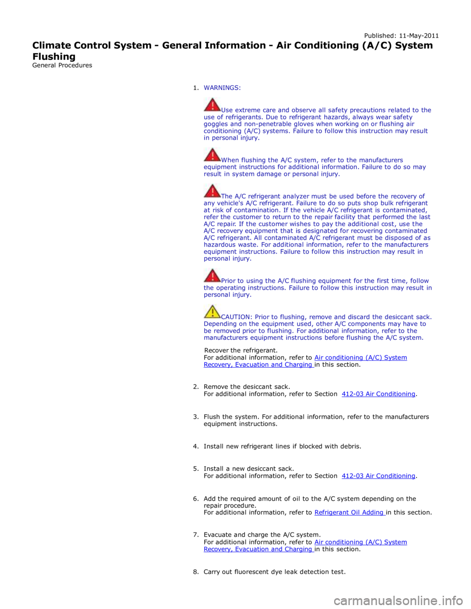
Published: 11-May-2011
Climate Control System - General Information - Air Conditioning (A/C) System
Flushing
General Procedures
1. WARNINGS:
Use extreme care and observe all safety precautions related to the
use of refrigerants. Due to refrigerant hazards, always wear safety
goggles and non-penetrable gloves when working on or flushing air
conditioning (A/C) systems. Failure to follow this instruction may result
in personal injury.
When flushing the A/C system, refer to the manufacturers
equipment instructions for additional information. Failure to do so may
result in system damage or personal injury.
The A/C refrigerant analyzer must be used before the recovery of
any vehicle's A/C refrigerant. Failure to do so puts shop bulk refrigerant
at risk of contamination. If the vehicle A/C refrigerant is contaminated,
refer the customer to return to the repair facility that performed the last
A/C repair. If the customer wishes to pay the additional cost, use the
A/C recovery equipment that is designated for recovering contaminated
A/C refrigerant. All contaminated A/C refrigerant must be disposed of as
hazardous waste. For additional information, refer to the manufacturers
equipment instructions. Failure to follow this instruction may result in
personal injury.
Prior to using the A/C flushing equipment for the first time, follow
the operating instructions. Failure to follow this instruction may result in
personal injury.
CAUTION: Prior to flushing, remove and discard the desiccant sack.
Depending on the equipment used, other A/C components may have to
be removed prior to flushing. For additional information, refer to the
manufacturers equipment instructions before flushing the A/C system.
Recover the refrigerant.
For additional information, refer to Air conditioning (A/C) System Recovery, Evacuation and Charging in this section.
2. Remove the desiccant sack.
For additional information, refer to Section 412-03 Air Conditioning.
3. Flush the system. For additional information, refer to the manufacturers
equipment instructions.
4. Install new refrigerant lines if blocked with debris.
5. Install a new desiccant sack.
For additional information, refer to Section 412-03 Air Conditioning.
6. Add the required amount of oil to the A/C system depending on the
repair procedure.
For additional information, refer to Refrigerant Oil Adding in this section.
7. Evacuate and charge the A/C system.
For additional information, refer to Air conditioning (A/C) System Recovery, Evacuation and Charging in this section.
8. Carry out fluorescent dye leak detection test.
Page 1701 of 3039
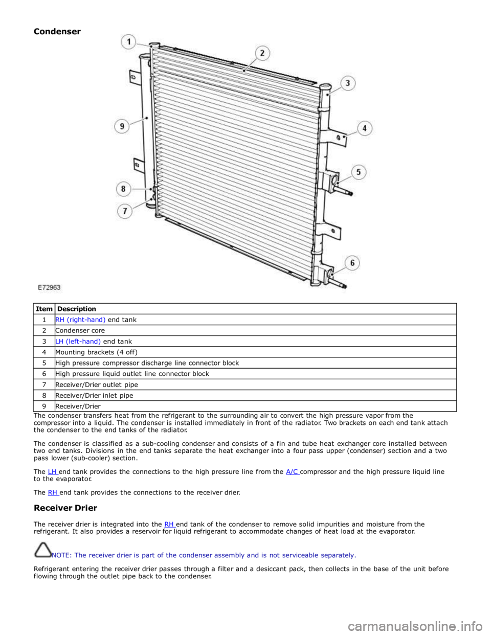
Item Description 1 RH (right-hand) end tank 2 Condenser core 3 LH (left-hand) end tank 4 Mounting brackets (4 off) 5 High pressure compressor discharge line connector block 6 High pressure liquid outlet line connector block 7 Receiver/Drier outlet pipe 8 Receiver/Drier inlet pipe 9 Receiver/Drier The condenser transfers heat from the refrigerant to the surrounding air to convert the high pressure vapor from the
compressor into a liquid. The condenser is installed immediately in front of the radiator. Two brackets on each end tank attach
the condenser to the end tanks of the radiator.
The condenser is classified as a sub-cooling condenser and consists of a fin and tube heat exchanger core installed between
two end tanks. Divisions in the end tanks separate the heat exchanger into a four pass upper (condenser) section and a two
pass lower (sub-cooler) section.
The LH end tank provides the connections to the high pressure line from the A/C compressor and the high pressure liquid line to the evaporator.
The RH end tank provides the connections to the receiver drier.
Receiver Drier
The receiver drier is integrated into the RH end tank of the condenser to remove solid impurities and moisture from the refrigerant. It also provides a reservoir for liquid refrigerant to accommodate changes of heat load at the evaporator.
NOTE: The receiver drier is part of the condenser assembly and is not serviceable separately.
Refrigerant entering the receiver drier passes through a filter and a desiccant pack, then collects in the base of the unit before
flowing through the outlet pipe back to the condenser. Condenser
Page 1702 of 3039
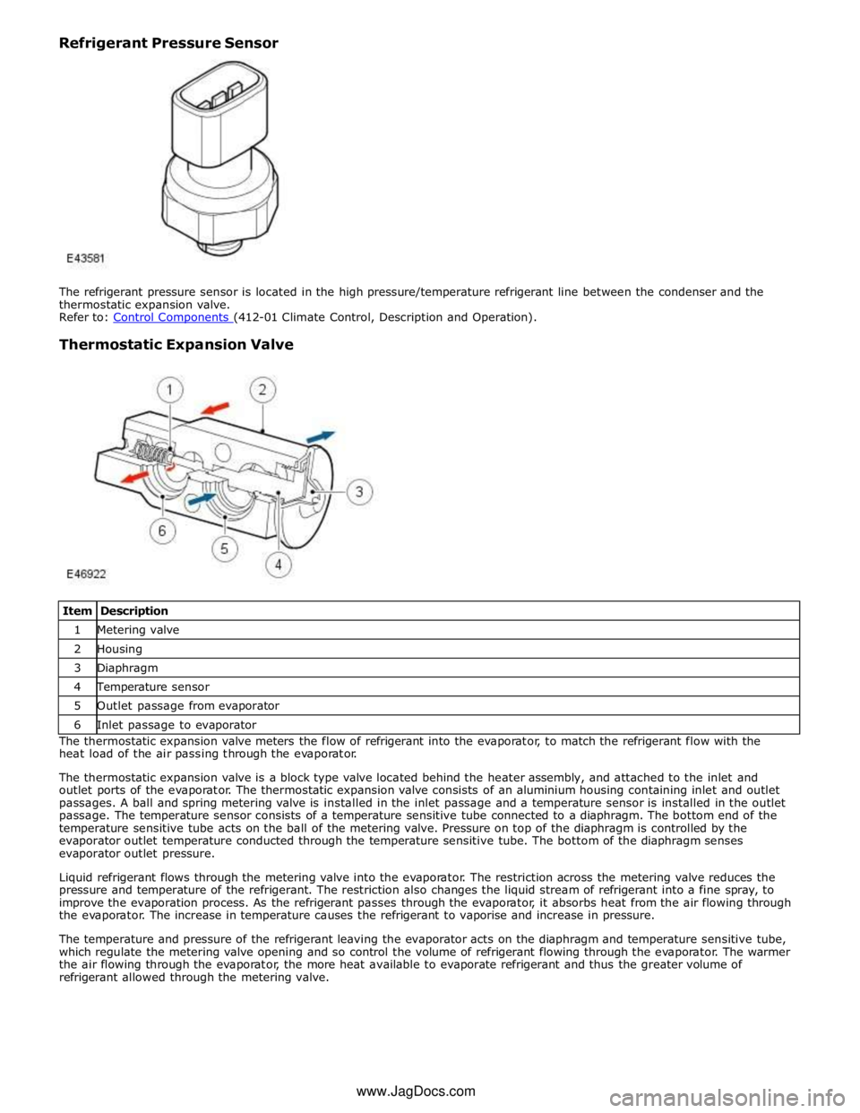
Thermostatic Expansion Valve
Item Description 1 Metering valve 2 Housing 3 Diaphragm 4 Temperature sensor 5 Outlet passage from evaporator 6 Inlet passage to evaporator The thermostatic expansion valve meters the flow of refrigerant into the evaporator, to match the refrigerant flow with the
heat load of the air passing through the evaporator.
The thermostatic expansion valve is a block type valve located behind the heater assembly, and attached to the inlet and
outlet ports of the evaporator. The thermostatic expansion valve consists of an aluminium housing containing inlet and outlet
passages. A ball and spring metering valve is installed in the inlet passage and a temperature sensor is installed in the outlet
passage. The temperature sensor consists of a temperature sensitive tube connected to a diaphragm. The bottom end of the
temperature sensitive tube acts on the ball of the metering valve. Pressure on top of the diaphragm is controlled by the
evaporator outlet temperature conducted through the temperature sensitive tube. The bottom of the diaphragm senses
evaporator outlet pressure.
Liquid refrigerant flows through the metering valve into the evaporator. The restriction across the metering valve reduces the
pressure and temperature of the refrigerant. The restriction also changes the liquid stream of refrigerant into a fine spray, to
improve the evaporation process. As the refrigerant passes through the evaporator, it absorbs heat from the air flowing through
the evaporator. The increase in temperature causes the refrigerant to vaporise and increase in pressure.
The temperature and pressure of the refrigerant leaving the evaporator acts on the diaphragm and temperature sensitive tube,
which regulate the metering valve opening and so control the volume of refrigerant flowing through the evaporator. The warmer
the air flowing through the evaporator, the more heat available to evaporate refrigerant and thus the greater volume of
refrigerant allowed through the metering valve. www.JagDocs.com