Page 802 of 3039

Turn signal indicators
Side lamps
Headlamps
Auto lamps
High/low beam
Headlamp flash
Headlamp timer
Trip computer.
The switch is located in a slot in the clockspring and secured with 2 plastic clips.
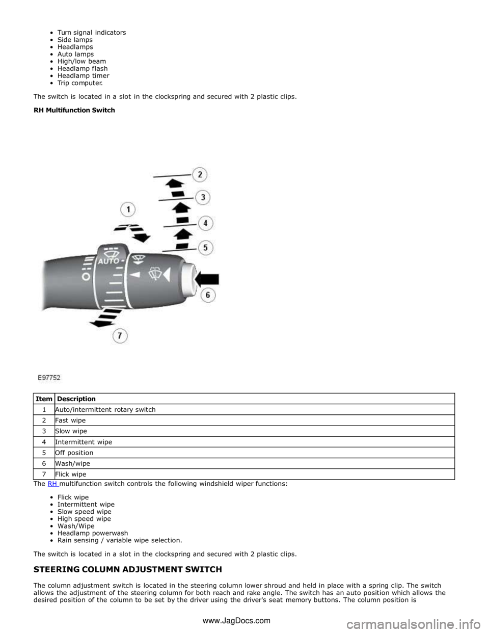
RH Multifunction Switch
The RH multifunction switch controls the following windshield wiper functions: Flick wipe
Intermittent wipe
Slow speed wipe
High speed wipe
Wash/Wipe
Headlamp powerwash
Rain sensing / variable wipe selection.
The switch is located in a slot in the clockspring and secured with 2 plastic clips.
STEERING COLUMN ADJUSTMENT SWITCH
The column adjustment switch is located in the steering column lower shroud and held in place with a spring clip. The switch
allows the adjustment of the steering column for both reach and rake angle. The switch has an auto position which allows the
desired position of the column to be set by the driver using the driver's seat memory buttons. The column position is Item Description 1 Auto/intermittent rotary switch 2 Fast wipe 3 Slow wipe 4 Intermittent wipe 5 Off position 6 Wash/wipe 7 Flick wipe www.JagDocs.com
Page 803 of 3039
automatically reset once the applicable remote handset has been detected by the vehicle security systems.
STEERING WHEEL HEATER
On certain models the rim of the steering wheel contains a heater element. Operation of the heater is selected using the
Touch Screen Display (TSD).
The heater temperature is controlled by a heated steering wheel control module located within the steering wheel. Power for
the heater element is supplied to the steering wheel via 2 contacts on the clockspring and a slip ring mounted on the steering
wheel.
Page 886 of 3039
6. CAUTIONS:
Only rotate the crankshaft clockwise.
Make sure that the crankshaft is fully locked.
Install the Special Tool(s): 303-1447
7. Using a suitable marker, mark the position of the crankshaft pulley as
illustrated.
8.
9. NOTE: Discard the seal. www.JagDocs.com
Page 899 of 3039

Engine - V8 S/C 5.0L Petrol - Valve Clearance Check
General Procedures
Check Published: 10-Jul-2013
1. Refer to: Battery Disconnect and Connect (414-01 Battery, Mounting and Cables, General Procedures).
2. WARNING: Do not work on or under a vehicle supported only by a jack.
Always support the vehicle on safety stands.
Raise and support the vehicle.
3. Refer to: Valve Cover LH (303-01D Engine - V8 S/C 5.0L Petrol, Removal and Installation).
4. Refer to: Valve Cover RH (303-01D Engine - V8 S/C 5.0L Petrol, Removal and Installation).
5. CAUTIONS:
Rotate the engine clockwise until the camshafts are positioned as
shown.
Do not rotate the crankshaft counterclockwise. The timing chains
may bind causing engine damage.
Camshaft lobes must be 180 degrees away from each valve tappet
or valve clearance will be incorrect.
NOTE: Using feeler gauge check the gap between the tappet and
the camshaft lobe and check against specifications table.
Using feeler gauge check the gap between the tappet and the
camshaft lobe and check against specifications table.
Repeat for the remaining valve tappets.
Page 903 of 3039

Installation
1. CAUTIONS:
Prior to installing the camshafts, position the
crankshaft 45 degrees ATDC cylinder 1A to prevent
valve/piston collision.
Make sure that the camshafts and camshaft bearing
caps are installed in their original locations.
Evenly and progressively install and tighten the
camshaft bearing caps.
NOTE: Lubricate the camshafts and the camshaft
bearing caps with EP90 oil (or 75/90 viscosity oil will
suffice) prior to installation.
Torque: 3 Nm
2. NOTE: Tighten the bolts in the indicated sequence.
Torque: 12 Nm
3. CAUTION: Only rotate the crankshaft clockwise.
Rotate the crankshaft untill the camshaft lobe on the valve being
checked is 180 degrees from the maximum opening position.
4. NOTE: If the valve clearance is incorrect, continue to the next step. If
the valve clearance is correct, continue to step 8.
Using feeler gauge check the gap between the tappet and the camshaft
lobe and check against specifications table.
5. CAUTIONS:
Do not use a magnet to remove the tappet.
Use the following formula to calculate the required bucket
thickness. Original thickness + measured clearance - desired clearance =
required bucket thickness.
Remove the tappet and measure the thickness.
Page 906 of 3039

Installation
1. CAUTIONS:
Prior to installing the camshafts, position the
crankshaft 45 degrees ATDC cylinder 1A to prevent
valve/piston collision.
Evenly and progressively install and tighten the
camshaft bearing caps.
Make sure that the camshafts and camshaft bearing
caps are installed in their original locations.
NOTE: Lubricate the camshafts and the camshaft
bearing caps with EP90 oil (or 75/90 viscosity oil will
suffice) prior to installation.
Torque: 3 Nm
2. NOTE: Tighten the bolts in the indicated sequence.
Torque: 12 Nm
3. CAUTION: Only rotate the crankshaft clockwise.
Rotate the crankshaft untill the camshaft lobe on the valve being
checked is 180 degrees from the maximum opening position.
4. NOTE: If the valve clearance is incorrect, continue to the next step. If
the valve clearance is correct, continue to step 8.
Using feeler gauge check the gap between the tappet and the camshaft
lobe and check against specifications table.
5. CAUTIONS:
Use the following formula to calculate the required bucket
thickness. Original thickness + measured clearance - desired clearance =
required bucket thickness.
Do not use a magnet to remove the tappet.
Remove the tappet and measure the thickness. www.JagDocs.com
Page 923 of 3039
6. CAUTION: Rotate the crankshaft pulley installation tool
anti-clockwise until the pulley is fully located, do not over
tighten. Failure to do this may result in damge to the
components.
7. Remove the special tool.
Page 1033 of 3039
Some variation in the illustrations may occur, but the essential information is always correct.
1. Disconnect the battery ground cable.
Refer to: Battery Disconnect and Connect (414-01 Battery, Mounting and Cables, General Procedures).
2. WARNING: Make sure to support the vehicle with axle stands.
Raise and support the vehicle.
3. Refer to: Timing Cover (303-01C Engine - V8 5.0L Petrol, Removal and Installation).
4.
5. CAUTION: Only rotate the crankshaft clockwise.
Install the special tool.
Special Tool(s): 303-1447