2010 JAGUAR XFR clock
[x] Cancel search: clockPage 722 of 3039

Noise
Symptom Possible Causes Action
Continuous noise
Low power steering fluid level
Check for leaks and rectify as required. For further
information refer to the symptom charts for
leakage in this section. Fill power steering fluid
reservoir to correct level
NOTE: Look for small air bubbles
visible in the fluid, air may also get
trapped in the hydraulic system
Air in hydraulic system
Bleed the power steering system.
REFER to: Power Steering System Bleeding (211-00 Steering System - General Information,
General Procedures).
Power steering pipe/hose in
contact with the vehicle body
Check and reposition, or install new IF
damaged/deformed, power steering pipe/hose
Power steering pipe/hose
restricted or twisted
Check and clear restriction to pipe/hose
Reposition power steering pipe/hose. Install new
pipe/hose IF permanently damaged/deformed
Power steering pump mounting
bolts loose
Tighten the power steering pump mounting bolts
to the correct torque.
REFER to: Specifications (211-00 Steering System - General Information, Specifications).
Noise gets worse
when system is
loaded
NOTE: Refer to the power
steering pressure check in this section
Low power steering fluid level
Aerated fluid
Low power steering pump
pressure
Check and fill power steering fluid reservoir to
correct level
Bleed the power steering system.
REFER to: Power Steering System Bleeding (211-00 Steering System - General Information,
General Procedures).
Check power steering pump pressure. If the pump
pressure is low, install a new power steering
pump
Front End Accessory
Drive (FEAD) belt
squeal
FEAD belt incorrectly tensioned
or glazed
Check FEAD belt tension
Check FEAD belt condition and install a new belt
as required
Chirp noise from the
steering pump when a
load is applied
Loose or worn FEAD belt
Check FEAD belt tension
Check FEAD belt condition and install a new belt
as required
Scrape/grind noise
from behind steering
wheel while steering
Steering column shroud foul
condition or clockspring
Correctly install the steering column shroud to
eliminate the foul condition
Install a new clockspring as required
Foreign objects
Remove foreign objects from between steering
column shroud and steering wheel/steering
column rotating components
Click
Clockspring or steering column
multifunction switch LH
Correctly install and install new components as
required
Loose universal joint pinch bolt
Install a new universal joint pinch bolt and
tighten to correct specification.
REFER to: Specifications (211-00 Steering System - General Information, Specifications).
Squeak
Steering column shroud joints
Apply Krytox spray to steering column shroud
joints
Clockspring
Install new clockspring as required
Page 744 of 3039

1 Return fluid control groove 2 Radial groove 3 Feed fluid control groove 4 Radial groove 5 Axial groove 6 Feed fluid control edge 7 Feed fluid radial groove 8 Return fluid control edge 9 Return fluid chamber 10 Cut-off valve 11 Radial groove 12 Servotronic transducer valve 13 Feed fluid radial groove 14 Radial groove 15 Orifice 16 Balls 17 Compression spring 18 Torsion bar 19 Power steering fluid reservoir 20 Valve rotor 21 Reaction piston 22 Reaction chamber 23 Centering piece 24 Pressure relief/flow limiting valve 25 Power steering pump 26 Inner tie-rod 27 Pinion 28 Valve sleeve 29 Steering gear rack 30 Steering gear housing 31 Power assist cylinder - right 32 Piston 33 Power assist cylinder - left When the steering wheel is turned to the right, the steering rack and piston moves to the left in the piston bore. The valve
rotor is rotated to the right (clockwise) and pressurized fluid is directed over the further opened feed fluid control edges and to
the associated axial grooves, the radial groove and via an external pipe to the left power assist cylinder chamber. The pressure
applied to the piston from the left power assist cylinder chamber provides the hydraulic assistance.
An adaptable pressure build-up is achieved by the partially or fully closed feed fluid control edges restricting or preventing a
connection between the fluid pressure inlet and the other axial grooves connected to the radial groove.
Simultaneously, the fluid pressure outlet to the pressurized axial grooves are restricted or partially restricted by the closing
return fluid control edges. The fluid displaced by the piston from the right power assist cylinder chamber, flows through an
external pipe to the radial grooves. From there the fluid passes to the associated axial grooves and on to the return fluid
control grooves, via the further opened return fluid control edges.
The return flow of fluid to the reservoir passes via interconnecting bores which lead to the return fluid chamber. When the
steering wheel is turned to the left the operating sequence is as above but the pressure is applied to the opposite side of the
piston.
Servotronic Operation
The Servotronic software contains a number of steering maps which are selected via the car configuration file depending on the
vehicle mode and tire fitment.
If a failure of the Servotronic valve or software occurs, the system will suspend Servotronic assistance and only normal power
steering wheel be available. Fault codes relating to the fault are stored, but no warning lamps are illuminated and the driver
may be aware of the steering being 'heavier' than usual.
When the vehicle is manoeuvred into and out of a parking space (or other similar manoeuvre), the Servotronic software uses
road speed data from the ABS module to determine the vehicle speed, which in this case will be slow or stationary. The
Servotronic software analyses the signals and outputs an appropriate control current to the Servotronic transducer valve. The
Servotronic valve closes and prevents fluid flowing from the feed fluid radial groove to the reaction chamber. An orifice also
Page 753 of 3039

Power Steering - Steering Gear
Removal and Installation Published: 04-Jul-2013
CAUTIONS: Removal
Make sure that only the manufacturers' recommended four wheel alignment equipment is used.
Do not turn the steering wheel with the steering column lower shaft disconnected as damage to the clockspring and
steering wheel switches may occur.
NOTES:
Make sure the steering is in the straight ahead position.
RHD illustration shown, LHD is similar.
Some variation in the illustrations may occur, but the essential information is always correct.
1. Raise and support the vehicle.
2. Center the steering wheel.
Lock in position and remove the ignition key.
3. Remove the front wheels and tires.
For additional information, refer to: Wheel and Tire (204-04 Wheels and Tires, Removal and Installation).
4. Remove the air deflector.
For additional information, refer to: Air Deflector (501-02 Front End Body Panels, Removal and Installation).
Page 782 of 3039
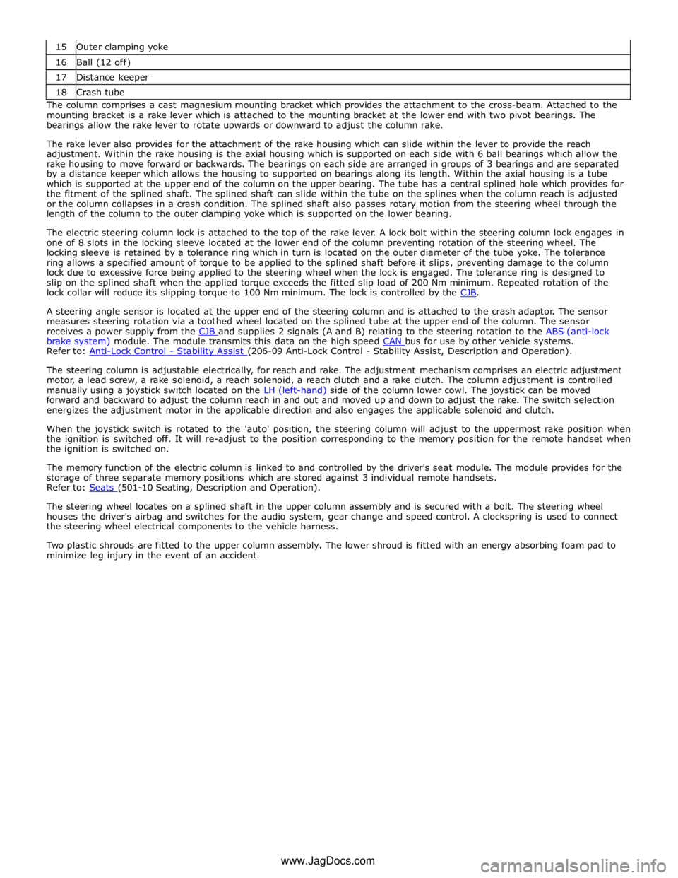
16 Ball (12 off) 17 Distance keeper 18 Crash tube The column comprises a cast magnesium mounting bracket which provides the attachment to the cross-beam. Attached to the
mounting bracket is a rake lever which is attached to the mounting bracket at the lower end with two pivot bearings. The
bearings allow the rake lever to rotate upwards or downward to adjust the column rake.
The rake lever also provides for the attachment of the rake housing which can slide within the lever to provide the reach
adjustment. Within the rake housing is the axial housing which is supported on each side with 6 ball bearings which allow the
rake housing to move forward or backwards. The bearings on each side are arranged in groups of 3 bearings and are separated
by a distance keeper which allows the housing to supported on bearings along its length. Within the axial housing is a tube
which is supported at the upper end of the column on the upper bearing. The tube has a central splined hole which provides for
the fitment of the splined shaft. The splined shaft can slide within the tube on the splines when the column reach is adjusted
or the column collapses in a crash condition. The splined shaft also passes rotary motion from the steering wheel through the
length of the column to the outer clamping yoke which is supported on the lower bearing.
The electric steering column lock is attached to the top of the rake lever. A lock bolt within the steering column lock engages in
one of 8 slots in the locking sleeve located at the lower end of the column preventing rotation of the steering wheel. The
locking sleeve is retained by a tolerance ring which in turn is located on the outer diameter of the tube yoke. The tolerance
ring allows a specified amount of torque to be applied to the splined shaft before it slips, preventing damage to the column
lock due to excessive force being applied to the steering wheel when the lock is engaged. The tolerance ring is designed to
slip on the splined shaft when the applied torque exceeds the fitted slip load of 200 Nm minimum. Repeated rotation of the
lock collar will reduce its slipping torque to 100 Nm minimum. The lock is controlled by the CJB.
A steering angle sensor is located at the upper end of the steering column and is attached to the crash adaptor. The sensor
measures steering rotation via a toothed wheel located on the splined tube at the upper end of the column. The sensor
receives a power supply from the CJB and supplies 2 signals (A and B) relating to the steering rotation to the ABS (anti-lock brake system) module. The module transmits this data on the high speed CAN bus for use by other vehicle systems. Refer to: Anti-Lock Control - Stability Assist (206-09 Anti-Lock Control - Stability Assist, Description and Operation).
The steering column is adjustable electrically, for reach and rake. The adjustment mechanism comprises an electric adjustment
motor, a lead screw, a rake solenoid, a reach solenoid, a reach clutch and a rake clutch. The column adjustment is controlled
manually using a joystick switch located on the LH (left-hand) side of the column lower cowl. The joystick can be moved
forward and backward to adjust the column reach in and out and moved up and down to adjust the rake. The switch selection
energizes the adjustment motor in the applicable direction and also engages the applicable solenoid and clutch.
When the joystick switch is rotated to the 'auto' position, the steering column will adjust to the uppermost rake position when
the ignition is switched off. It will re-adjust to the position corresponding to the memory position for the remote handset when
the ignition is switched on.
The memory function of the electric column is linked to and controlled by the driver's seat module. The module provides for the
storage of three separate memory positions which are stored against 3 individual remote handsets.
Refer to: Seats (501-10 Seating, Description and Operation).
The steering wheel locates on a splined shaft in the upper column assembly and is secured with a bolt. The steering wheel
houses the driver's airbag and switches for the audio system, gear change and speed control. A clockspring is used to connect
the steering wheel electrical components to the vehicle harness.
Two plastic shrouds are fitted to the upper column assembly. The lower shroud is fitted with an energy absorbing foam pad to
minimize leg injury in the event of an accident.
www.JagDocs.com
Page 792 of 3039
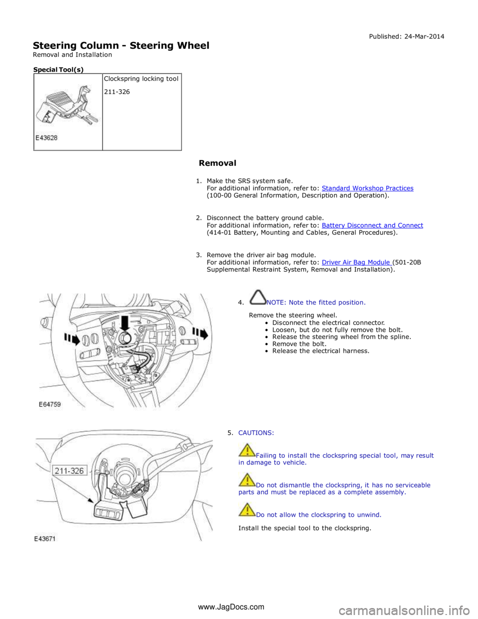
Steering Column - Steering Wheel
Removal and Installation Published: 24-Mar-2014
Removal
1. Make the SRS system safe.
For additional information, refer to: Standard Workshop Practices (100-00 General Information, Description and Operation).
2. Disconnect the battery ground cable.
For additional information, refer to: Battery Disconnect and Connect (414-01 Battery, Mounting and Cables, General Procedures).
3. Remove the driver air bag module.
For additional information, refer to: Driver Air Bag Module (501-20B Supplemental Restraint System, Removal and Installation).
4. NOTE: Note the fitted position.
Remove the steering wheel.
Disconnect the electrical connector.
Loosen, but do not fully remove the bolt.
Release the steering wheel from the spline.
Remove the bolt.
Release the electrical harness.
5. CAUTIONS:
Failing to install the clockspring special tool, may result
in damage to vehicle.
Do not dismantle the clockspring, it has no serviceable
parts and must be replaced as a complete assembly.
Do not allow the clockspring to unwind.
Install the special tool to the clockspring. Clockspring locking tool
211-326 Special Tool(s) www.JagDocs.com
Page 795 of 3039
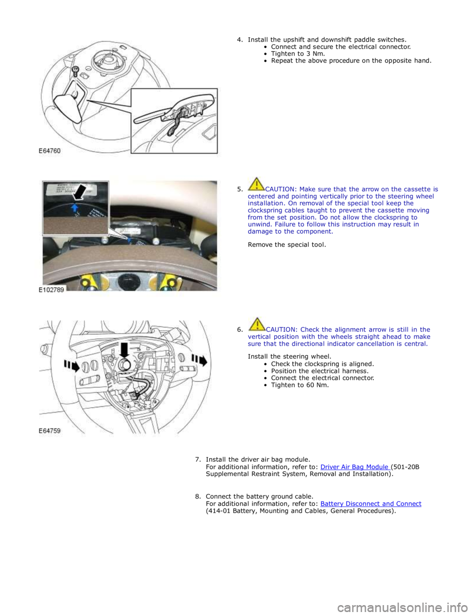
4. Install the upshift and downshift paddle switches.
Connect and secure the electrical connector.
Tighten to 3 Nm.
Repeat the above procedure on the opposite hand.
5. CAUTION: Make sure that the arrow on the cassette is
centered and pointing vertically prior to the steering wheel
installation. On removal of the special tool keep the
clockspring cables taught to prevent the cassette moving
from the set position. Do not allow the clockspring to
unwind. Failure to follow this instruction may result in
damage to the component.
Remove the special tool.
6. CAUTION: Check the alignment arrow is still in the
vertical position with the wheels straight ahead to make
sure that the directional indicator cancellation is central.
Install the steering wheel.
Check the clockspring is aligned.
Position the electrical harness.
Connect the electrical connector.
Tighten to 60 Nm.
7. Install the driver air bag module.
For additional information, refer to: Driver Air Bag Module (501-20B Supplemental Restraint System, Removal and Installation).
8. Connect the battery ground cable.
For additional information, refer to: Battery Disconnect and Connect (414-01 Battery, Mounting and Cables, General Procedures).
Page 796 of 3039
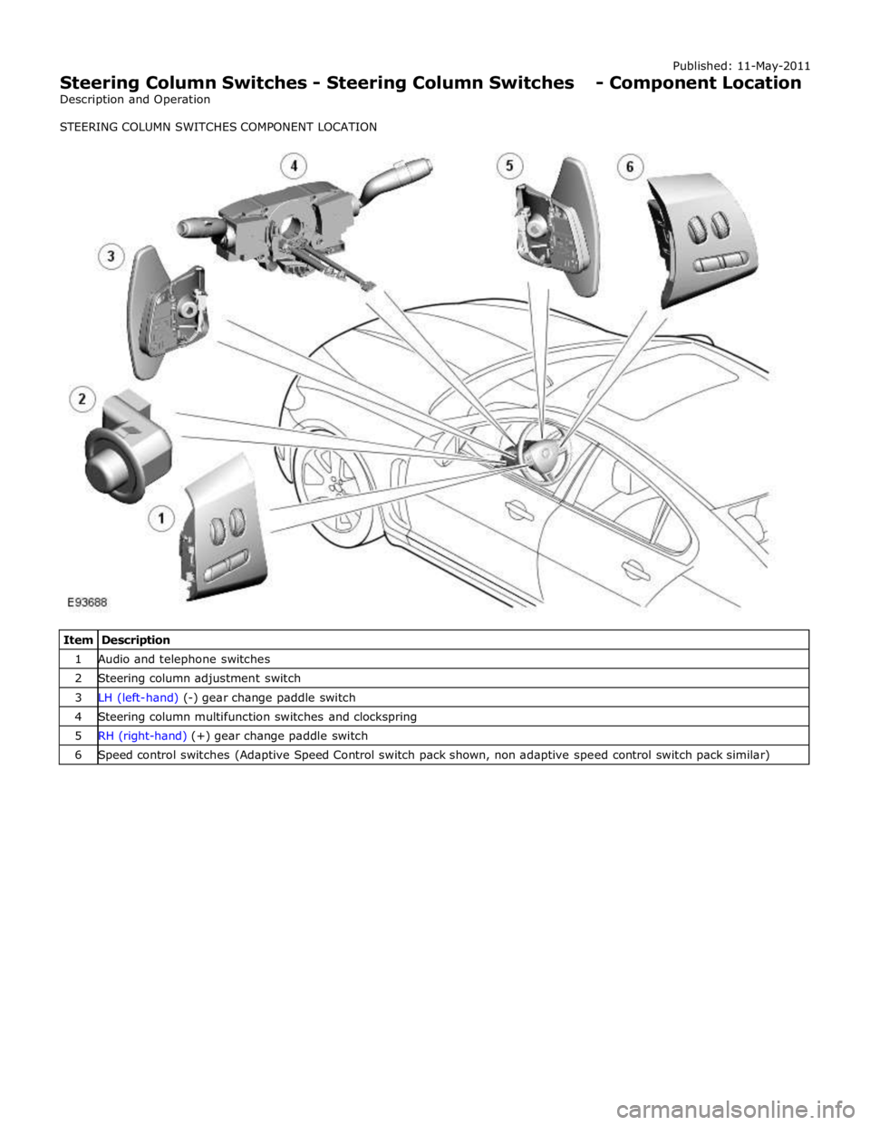
1 Audio and telephone switches 2 Steering column adjustment switch 3 LH (left-hand) (-) gear change paddle switch 4 Steering column multifunction switches and clockspring 5 RH (right-hand) (+) gear change paddle switch 6 Speed control switches (Adaptive Speed Control switch pack shown, non adaptive speed control switch pack similar)
Page 799 of 3039
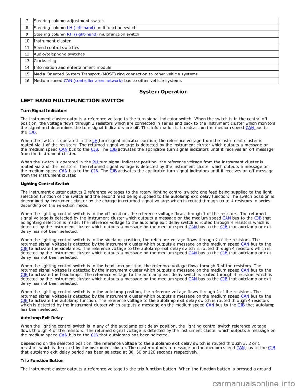
8 Steering column LH (left-hand) multifunction switch 9 Steering column RH (right-hand) multifunction switch 10 Instrument cluster 11 Speed control switches 12 Audio/telephone switches 13 Clockspring 14 Information and entertainment module 15 Media Oriented System Transport (MOST) ring connection to other vehicle systems 16 Medium speed CAN (controller area network) bus to other vehicle systems
LEFT HAND MULTIFUNCTION SWITCH
Turn Signal Indicators System Operation
The instrument cluster outputs a reference voltage to the turn signal indicator switch. When the switch is in the central off
position, the voltage flows through 3 resistors which are connected in series and back to the instrument cluster which monitors
the signal and determines the turn signal indicators are off. This information is broadcast on the medium speed CAN bus to the CJB.
When the switch is operated in the LH turn signal indicator position, the reference voltage from the instrument cluster is routed via 1 of the resistors. The returned signal voltage is detected by the instrument cluster which outputs a message on
the medium speed CAN bus to the CJB. The CJB activates the applicable turn signal indicators until it receives an off message from the instrument cluster.
When the switch is operated in the RH turn signal indicator position, the reference voltage from the instrument cluster is routed via 2 of the resistors. The returned signal voltage is detected by the instrument cluster which outputs a message on
the medium speed CAN bus to the CJB. The CJB activates the applicable turn signal indicators until it receives an off message from the instrument cluster.
Lighting Control Switch
The instrument cluster outputs 2 reference voltages to the rotary lighting control switch; one feed being supplied to the light
selection function of the switch and the second feed being supplied to the autolamp exit delay function. The switch position is
determined by instrument cluster by the change in returned signal voltage which is routed through up to 4 resistors in series
depending on the selection made.
When the lighting control switch is in the off position, the reference voltage flows through 1 of the resistors. The returned
signal voltage is detected by the instrument cluster which outputs a message on the medium speed CAN bus to the CJB that no lighting selection is made. The reference voltage to the autolamp exit delay switch is routed through 4 resistors which is
detected by the instrument cluster which outputs a message on the medium speed CAN bus to the CJB that autolamp or exit delay has not been selected.
When the lighting control switch is in the sidelamp position, the reference voltage flows through 2 of the resistors. The
returned signal voltage is detected by the instrument cluster which outputs a message on the medium speed CAN bus to the CJB to activate the sidelamps. The reference voltage to the autolamp exit delay switch is routed through 4 resistors which is detected by the instrument cluster which outputs a message on the medium speed CAN bus to the CJB that autolamp or exit delay has not been selected.
When the lighting control switch is in the headlamp position, the reference voltage flows through 3 of the resistors. The
returned signal voltage is detected by the instrument cluster which outputs a message on the medium speed CAN bus to the CJB to activate the headlamps. The reference voltage to the autolamp exit delay switch is routed through 4 resistors which is detected by the instrument cluster which outputs a message on the medium speed CAN bus to the CJB that autolamp or exit delay has not been selected.
When the lighting control switch is in the autolamp position, the reference voltage flows through 4 of the resistors. The
returned signal voltage is detected by the instrument cluster which outputs a message on the medium speed CAN bus to the CJB to activate the autolamp function. The reference voltage to the autolamp exit delay switch is routed through 4 resistors which is detected by the instrument cluster which outputs a message on the medium speed CAN bus to the CJB that autolamp has been selected.
Autolamp Exit Delay
When the lighting control switch is in any of the autolamp exit delay position, the lighting control switch reference voltage
flows through 4 of the resistors. The returned signal voltage is detected by the instrument cluster which outputs a message on
the medium speed CAN bus to the CJB that autolamps has been selected.
Depending on the selected position, the reference voltage to the autolamp exit delay switch is routed through 3, 2 or 1
resistors which is detected by the instrument cluster. The cluster outputs a message on the medium speed CAN bus to the CJB that autolamp exit delay period has been selected at 30, 60 or 120 seconds respectively.
Trip Function Button
The instrument cluster outputs a reference voltage to the trip function button. When the function button is pressed a ground