Page 1034 of 3039
6. CAUTION: If the noted postion of the woodruff key is
at the 9 o'clock position, then a new flexplate must be
installed. If the woodruff key is in the 6 o'clock position
then proceed with the next step.
Note the position of the crankshaft woodruff key.
7.
Page 1041 of 3039
5.
Install the special tool 303-1445 to the rear of the
camshafts making sure the key way's are correctly
located into each slot on each of the camshafts.
6. CAUTIONS:
Do not overturn the camshafts.
Tighten the wing nuts finger tight. Failure to follow
this instruction may result in damage to the components.
Using a suitable tool, carefully rock the camshaft
clockwise then anti-clockwise. Turn the special tool
locking nuts until there is no movement left in
camshafts.
Repeat steps 3- 6 for the camshafts on the other
cylinder head. www.JagDocs.com
Page 1054 of 3039
32.
Remove the special tool.
Special Tool(s): 303-1448
33. Rotate the engine two complete turns clockwise.
34.
35. CAUTION: Only rotate the crankshaft clockwise.
Install the special tool.
Special Tool(s): 303-1447
Install the special tool.
Special Tool(s): 303-1448
Page 1388 of 3039
Installation 5. WARNING: Fluid loss is unavoidable, use absorbent
cloth or a container to collect the fluid.
CAUTION: Engine coolant will damage the paint
finished surfaces. If spilt, immediately remove the coolant
and clean the area with water.
Lift the tang and rotate the engine coolant temperature
(ECT) sensor counter clockwise.
1. To install, reverse the removal procedure.
Page 1412 of 3039

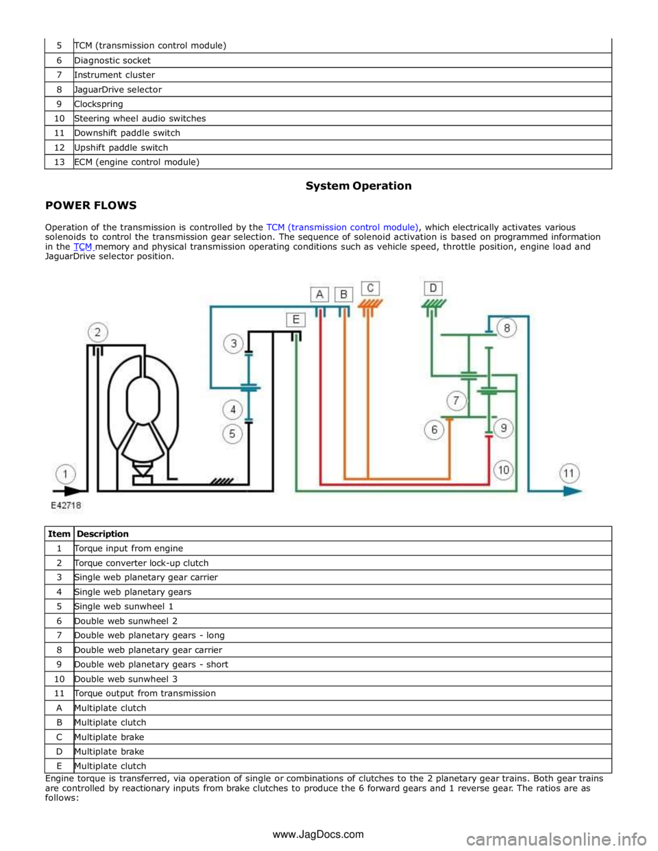
TCM (transmission control module) 6 Diagnostic socket 7 Instrument cluster 8 JaguarDrive selector 9 Clockspring 10 Steering wheel audio switches 11 Downshift paddle switch 12 Upshift paddle switch 13 ECM (engine control module)
POWER FLOWS System Operation
Operation of the transmission is controlled by the TCM (transmission control module), which electrically activates various
solenoids to control the transmission gear selection. The sequence of solenoid activation is based on programmed information
in the TCM memory and physical transmission operating conditions such as vehicle speed, throttle position, engine load and JaguarDrive selector position.
Item Description 1 Torque input from engine 2 Torque converter lock-up clutch 3 Single web planetary gear carrier 4 Single web planetary gears 5 Single web sunwheel 1 6 Double web sunwheel 2 7 Double web planetary gears - long 8 Double web planetary gear carrier 9 Double web planetary gears - short 10 Double web sunwheel 3 11 Torque output from transmission A Multiplate clutch B Multiplate clutch C Multiplate brake D Multiplate brake E Multiplate clutch Engine torque is transferred, via operation of single or combinations of clutches to the 2 planetary gear trains. Both gear trains
are controlled by reactionary inputs from brake clutches to produce the 6 forward gears and 1 reverse gear. The ratios are as
follows: www.JagDocs.com
Page 1426 of 3039

9 Journal - Drive plate/crankshaft location 10 Torque converter cover 11 Lock-up clutch piston 12 Lock-up clutch plate The torque converter is the coupling element between the engine and the transmission and is located in the bell housing, on
the engine side of the transmission. The driven power from the engine crankshaft is transmitted hydraulically and mechanically
through the torque converter to the transmission. The torque converter is connected to the engine by a drive plate attached to
the rear of the crankshaft.
The torque converter comprises an impeller, a stator and a turbine. The torque converter is a sealed unit with all components
located between the converter housing cover and the impeller. The two components are welded together to form a sealed, fluid
filled housing. With the impeller welded to the converter housing cover, the impeller is therefore driven at engine crankshaft
speed.
The converter housing cover has four threaded bosses, which provide for attachment of the engine drive plate. The threaded
bosses also provide for location of special tools which are required to remove the torque converter from the bell housing.
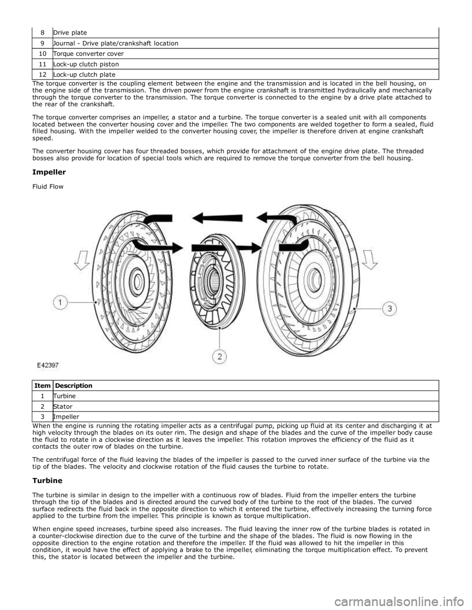
Impeller
Fluid Flow
Item Description 1 Turbine 2 Stator 3 Impeller When the engine is running the rotating impeller acts as a centrifugal pump, picking up fluid at its center and discharging it at
high velocity through the blades on its outer rim. The design and shape of the blades and the curve of the impeller body cause
the fluid to rotate in a clockwise direction as it leaves the impeller. This rotation improves the efficiency of the fluid as it
contacts the outer row of blades on the turbine.
The centrifugal force of the fluid leaving the blades of the impeller is passed to the curved inner surface of the turbine via the
tip of the blades. The velocity and clockwise rotation of the fluid causes the turbine to rotate.
Turbine
The turbine is similar in design to the impeller with a continuous row of blades. Fluid from the impeller enters the turbine
through the tip of the blades and is directed around the curved body of the turbine to the root of the blades. The curved
surface redirects the fluid back in the opposite direction to which it entered the turbine, effectively increasing the turning force
applied to the turbine from the impeller. This principle is known as torque multiplication.
When engine speed increases, turbine speed also increases. The fluid leaving the inner row of the turbine blades is rotated in
a counter-clockwise direction due to the curve of the turbine and the shape of the blades. The fluid is now flowing in the
opposite direction to the engine rotation and therefore the impeller. If the fluid was allowed to hit the impeller in this
condition, it would have the effect of applying a brake to the impeller, eliminating the torque multiplication effect. To prevent
this, the stator is located between the impeller and the turbine.
Page 1427 of 3039

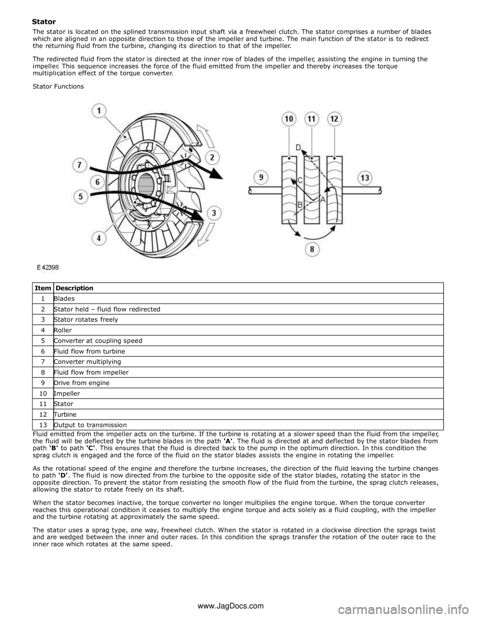
1 Blades 2 Stator held – fluid flow redirected 3 Stator rotates freely 4 Roller 5 Converter at coupling speed 6 Fluid flow from turbine 7 Converter multiplying 8 Fluid flow from impeller 9 Drive from engine 10 Impeller 11 Stator 12 Turbine 13 Output to transmission Fluid emitted from the impeller acts on the turbine. If the turbine is rotating at a slower speed than the fluid from the impeller,
the fluid will be deflected by the turbine blades in the path 'A'. The fluid is directed at and deflected by the stator blades from
path 'B' to path 'C'. This ensures that the fluid is directed back to the pump in the optimum direction. In this condition the
sprag clutch is engaged and the force of the fluid on the stator blades assists the engine in rotating the impeller.
As the rotational speed of the engine and therefore the turbine increases, the direction of the fluid leaving the turbine changes
to path 'D'. The fluid is now directed from the turbine to the opposite side of the stator blades, rotating the stator in the
opposite direction. To prevent the stator from resisting the smooth flow of the fluid from the turbine, the sprag clutch releases,
allowing the stator to rotate freely on its shaft.
When the stator becomes inactive, the torque converter no longer multiplies the engine torque. When the torque converter
reaches this operational condition it ceases to multiply the engine torque and acts solely as a fluid coupling, with the impeller
and the turbine rotating at approximately the same speed.
The stator uses a sprag type, one way, freewheel clutch. When the stator is rotated in a clockwise direction the sprags twist
and are wedged between the inner and outer races. In this condition the sprags transfer the rotation of the outer race to the
inner race which rotates at the same speed. www.JagDocs.com
Page 1428 of 3039

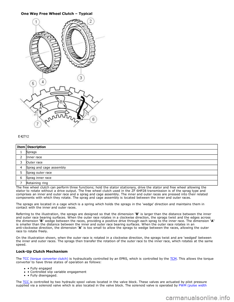
1 Sprags 2 Inner race 3 Outer race 4 Sprag and cage assembly 5 Sprag outer race 6 Sprag inner race 7 Retaining ring The free wheel clutch can perform three functions; hold the stator stationary, drive the stator and free wheel allowing the
stator to rotate without a drive output. The free wheel clutch used in the ZF 6HP28 transmission is of the sprag type and
comprises an inner and outer race and a sprag and cage assembly. The inner and outer races are pressed into their related
components with which they rotate. The sprag and cage assembly is located between the inner and outer races.
The sprags are located in a cage which is a spring which holds the sprags in the 'wedge' direction and maintains them in
contact with the inner and outer races.
Referring to the illustration, the sprags are designed so that the dimension 'B' is larger than the distance between the inner
and outer race bearing surfaces. When the outer race rotates in a clockwise direction, the sprags twist and the edges across
the dimension 'B' wedge between the races, providing a positive drive through each sprag to the inner race. The dimension 'A'
is smaller than the distance between the inner and outer race bearing surfaces. When the outer race rotates in an
anti-clockwise direction, the dimension 'A' is too small to allow the sprags to wedge between the races, allowing the outer
race to rotate freely.
On the illustration shown, when the outer race is rotated in a clockwise direction, the sprags twist and are 'wedged' between
the inner and outer races. The sprags then transfer the rotation of the outer race to the inner race, which rotates at the same
speed.
Lock-Up Clutch Mechanism
The TCC (torque converter clutch) is hydraulically controlled by an EPRS, which is controlled by the TCM. This allows the torque converter to have three states of operation as follows:
• Fully engaged
• Controlled slip variable engagement
• Fully disengaged.
The TCC is controlled by two hydraulic spool valves located in the valve block. These valves are actuated by pilot pressure supplied via a solenoid valve which is also located in the valve block. The solenoid valve is operated by PWM (pulse width One Way Free Wheel Clutch – Typical