2010 JAGUAR XFR clock
[x] Cancel search: clockPage 1981 of 3039
Navigation Destination, stored locations, navigation setup, route options Vehicle
Security, parking, valet mode, trip computer, clock, brightness, contrast, system settings, vehicle settings, display settings The screen is a touch sensitive 7 inch LCD (liquid crystal display) VGA screen containing 800 x 480 pixels in a 15:9 format. The
screen processes its own video for system operation but receives the navigation graphics from the navigation computer.
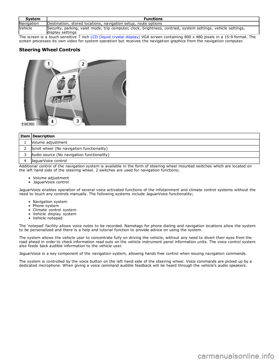
Steering Wheel Controls
Item Description 1 Volume adjustment 2 Scroll wheel (No navigation functionality) 3 Audio source (No navigation functionality) 4 JaguarVoice control Additional control of the navigation system is available in the form of steering wheel mounted switches which are located on
the left hand side of the steering wheel. 2 switches are used for navigation functions;
Volume adjustment
JaguarVoice control
JaguarVoice enables operation of several voice activated functions of the infotainment and climate control systems without the
need to touch any controls manually. The following systems include JaguarVoice functionality;
Navigation system
Phone system
Climate control system
Vehicle display system
Vehicle notepad
The 'notepad' facility allows voice notes to be recorded. Nametags for phone dialing and navigation locations allow the system
to be personalized and there is a help and tutorial function to provide advice on using the system.
The system allows the vehicle user to concentrate fully on driving the vehicle, without any need to divert their eyes from the
road ahead in order to check information read outs on the vehicle instrument panel information units. The voice control system
also feeds back audible information to the vehicle user.
JaguarVoice is a key component of the navigation system, allowing hands free control when issuing navigation commands.
The system is controlled by the voice button on the left hand side of the steering wheel. Voice commands are picked up by a
dedicated microphone. When giving a voice command audible feedback will be heard through the vehicle’s audio speakers.
Page 2030 of 3039
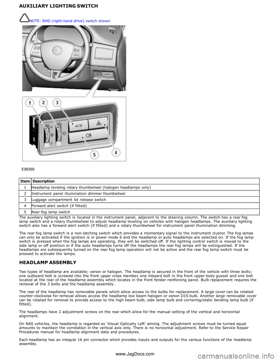
1 Headlamp leveling rotary thumbwheel (halogen headlamps only) 2 Instrument panel illumination dimmer thumbwheel 3 Luggage compartment lid release switch 4 Forward alert switch (if fitted) 5 Rear fog lamp switch The auxiliary lighting switch is located in the instrument panel, adjacent to the steering column. The switch has a rear fog
lamp switch and a rotary thumbwheel to adjust headlamp leveling on vehicles with halogen headlamps. The auxiliary lighting
switch also has a forward alert switch (if fitted) and a rotary thumbwheel for instrument panel illumination dimming.
The rear fog lamp switch is a non-latching switch which provides a momentary signal to the instrument cluster. The fog lamps
can only be activated if the ignition is in power mode 6 and the headlamp or auto headlamps are selected on. If the fog lamp
switch is pressed when the fog lamps are operating, they will be switched off. If the lighting control switch is moved to the
side lamp or off position or if the auto headlamps turns off the headlamps the rear fog lamps will be extinguished. If the
headlamps are subsequently turned on the rear fog lamp operation will not be active and the rear fog lamp switch must be
pressed to activate the lamps.
HEADLAMP ASSEMBLY
Two types of headlamp are available; xenon or halogen. The headlamp is secured in the front of the vehicle with three bolts;
one outboard bolt is screwed into the front upper cross member, one inboard bolt in the front upper body gusset and one bolt
located at the rear of the headlamp assembly which locates in the front fender reinforcing panel. Bulb replacement requires the
removal of the 3 bolts and the headlamp assembly.
The rear of the headlamp has removable panels which allow access to the bulbs for replacement. A large cover can be rotated
counter-clockwise for removal allows access the headlamp low beam halogen or xenon D1S bulb. Another large removable cover
can be rotated for removal to provide access to the high beam bulb, side lamp bulb and cornering/static bending lamp bulb (if
fitted).
The headlamps have 2 adjustment screws on the rear which allow for the manual setting of the vertical and horizontal
alignment.
On NAS vehicles, the headlamp is regarded as 'Visual Optically Left' aiming. The adjustment screws must be turned equal
amounts to maintain the correlation in the vertical axis only. There is no horizontal adjustment. Refer to the Service Repair
Procedures manual for headlamp alignment data and procedures.
Each headlamp has an integral 16 pin connector which provides inputs and outputs for the various functions of the headlamp
assembly. NOTE: RHD (right-hand drive) switch shown
www.JagDocs.com
Page 2069 of 3039

5 RJB (rear junction box) 6 Battery monitoring system module 7 Rear view camera 8 TCM (transmission control module) 9 Generator 10 Driver's door switch pack 11 Rear door control module 12 Driver's door control module 13 ECM (engine control module) 14 Electronic transmission selector 15 Driver's seat module 16 Driver's seat switch pack 17 Rear door control module 18 Front passenger door control module 19 Clockspring 20 Audio and telephone steering wheel switches 21 Instrument cluster 22 Start control module
Page 2163 of 3039
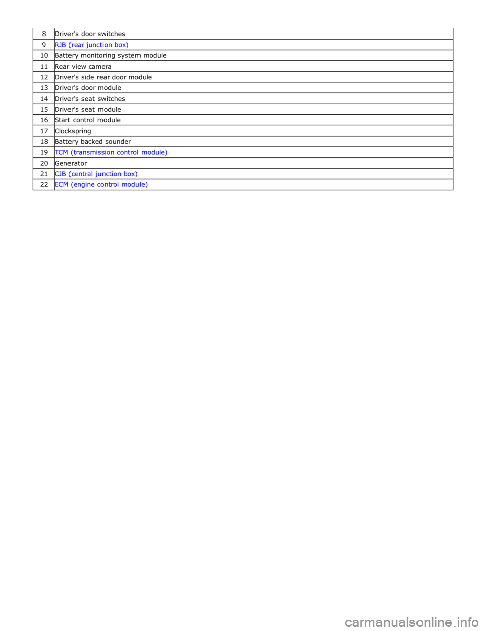
9 RJB (rear junction box) 10 Battery monitoring system module 11 Rear view camera 12 Driver's side rear door module 13 Driver's door module 14 Driver's seat switches 15 Driver's seat module 16 Start control module 17 Clockspring 18 Battery backed sounder 19 TCM (transmission control module) 20 Generator 21 CJB (central junction box) 22 ECM (engine control module)
Page 2172 of 3039
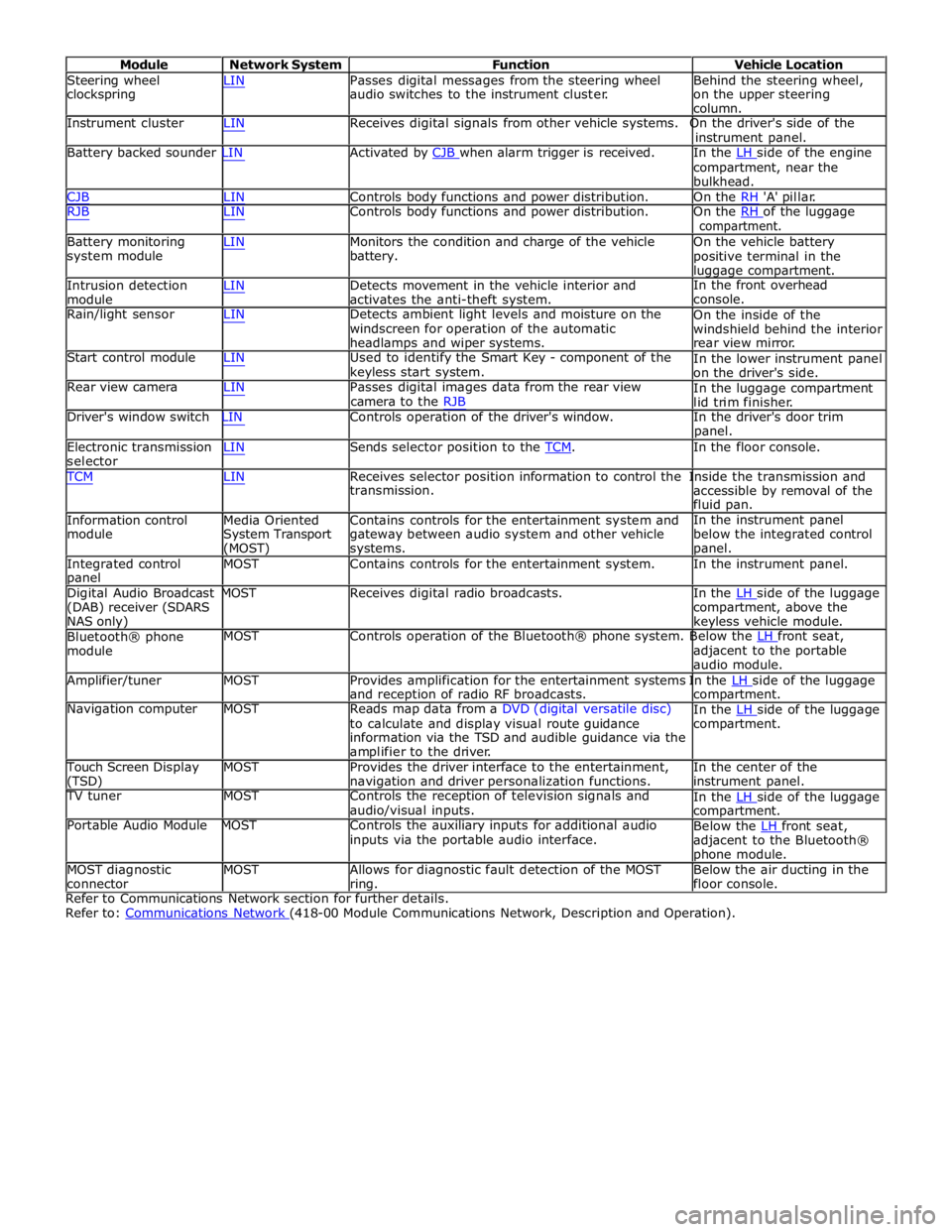
Module Network System Function Vehicle Location
Steering wheel
clockspring LIN Passes digital messages from the steering wheel
audio switches to the instrument cluster. Behind the steering wheel,
on the upper steering
column.
Instrument cluster LIN Receives digital signals from other vehicle systems. On the driver's side of the
instrument panel.
Battery backed sounder LIN Activated by CJB when alarm trigger is received. In the LH side of the engine compartment, near the
bulkhead.
CJB LIN Controls body functions and power distribution. On the RH 'A' pillar.
RJB LIN Controls body functions and power distribution. On the RH of the luggage compartment.
Battery monitoring
system module
Intrusion detection
module LIN Monitors the condition and charge of the vehicle
battery.
LIN Detects movement in the vehicle interior and
activates the anti-theft system. On the vehicle battery
positive terminal in the
luggage compartment.
In the front overhead
console.
Rain/light sensor LIN Detects ambient light levels and moisture on the
windscreen for operation of the automatic
headlamps and wiper systems.
Start control module LIN Used to identify the Smart Key - component of the
keyless start system.
Rear view camera LIN Passes digital images data from the rear view
camera to the RJB On the inside of the
windshield behind the interior
rear view mirror.
In the lower instrument panel
on the driver's side.
In the luggage compartment
lid trim finisher.
Driver's window switch LIN Controls operation of the driver's window. In the driver's door trim
panel.
Electronic transmission
selector LIN Sends selector position to the TCM. In the floor console. TCM LIN Receives selector position information to control the Inside the transmission and
Information control
module
Media Oriented
System Transport
(MOST) transmission.
Contains controls for the entertainment system and
gateway between audio system and other vehicle
systems. accessible by removal of the
fluid pan.
In the instrument panel
below the integrated control
panel.
Integrated control
panel MOST Contains controls for the entertainment system. In the instrument panel.
Digital Audio Broadcast MOST Receives digital radio broadcasts. In the LH side of the luggage (DAB) receiver (SDARS
NAS only)
Bluetooth® phone
module compartment, above the
keyless vehicle module.
MOST Controls operation of the Bluetooth® phone system. Below the LH front seat, adjacent to the portable
audio module.
Amplifier/tuner MOST Provides amplification for the entertainment systems In the LH side of the luggage and reception of radio RF broadcasts.
Navigation computer MOST Reads map data from a DVD (digital versatile disc)
to calculate and display visual route guidance
information via the TSD and audible guidance via the
amplifier to the driver. compartment.
In the LH side of the luggage compartment.
Touch Screen Display
(TSD) MOST Provides the driver interface to the entertainment,
navigation and driver personalization functions. In the center of the
instrument panel.
TV tuner MOST Controls the reception of television signals and
audio/visual inputs.
Portable Audio Module MOST Controls the auxiliary inputs for additional audio
inputs via the portable audio interface. In the LH side of the luggage compartment.
Below the LH front seat, adjacent to the Bluetooth®
phone module.
MOST diagnostic
connector MOST Allows for diagnostic fault detection of the MOST
ring. Below the air ducting in the
floor console.
Refer to Communications Network section for further details.
Refer to: Communications Network (418-00 Module Communications Network, Description and Operation).
Page 2542 of 3039
On vehicles with headlamp powerwash, each headlamp assembly is fitted with a headlamp powerwasher. The powerwasher is
located on the underside of the headlamp assembly. The powerwasher is located in a clip at the front of the headlamp and
secured with 2 self tapping screws to the headlamp body.
The powerwasher is a telescopic unit which extends forwards from the headlamp assembly under washer fluid pressure
supplied by the headlamp powerwash pump. When the pump pressure decreases the powerwasher is automatically retracted
back into the housing. The outer end of the powerwasher is fitted with a trim which blends the powerwasher into the headlamp
when it is not operating. The powerwasher has two washer jets which direct washer fluid under high pressure onto the
headlamp lens when the powerwasher is extended.
RAIN/LIGHT SENSOR
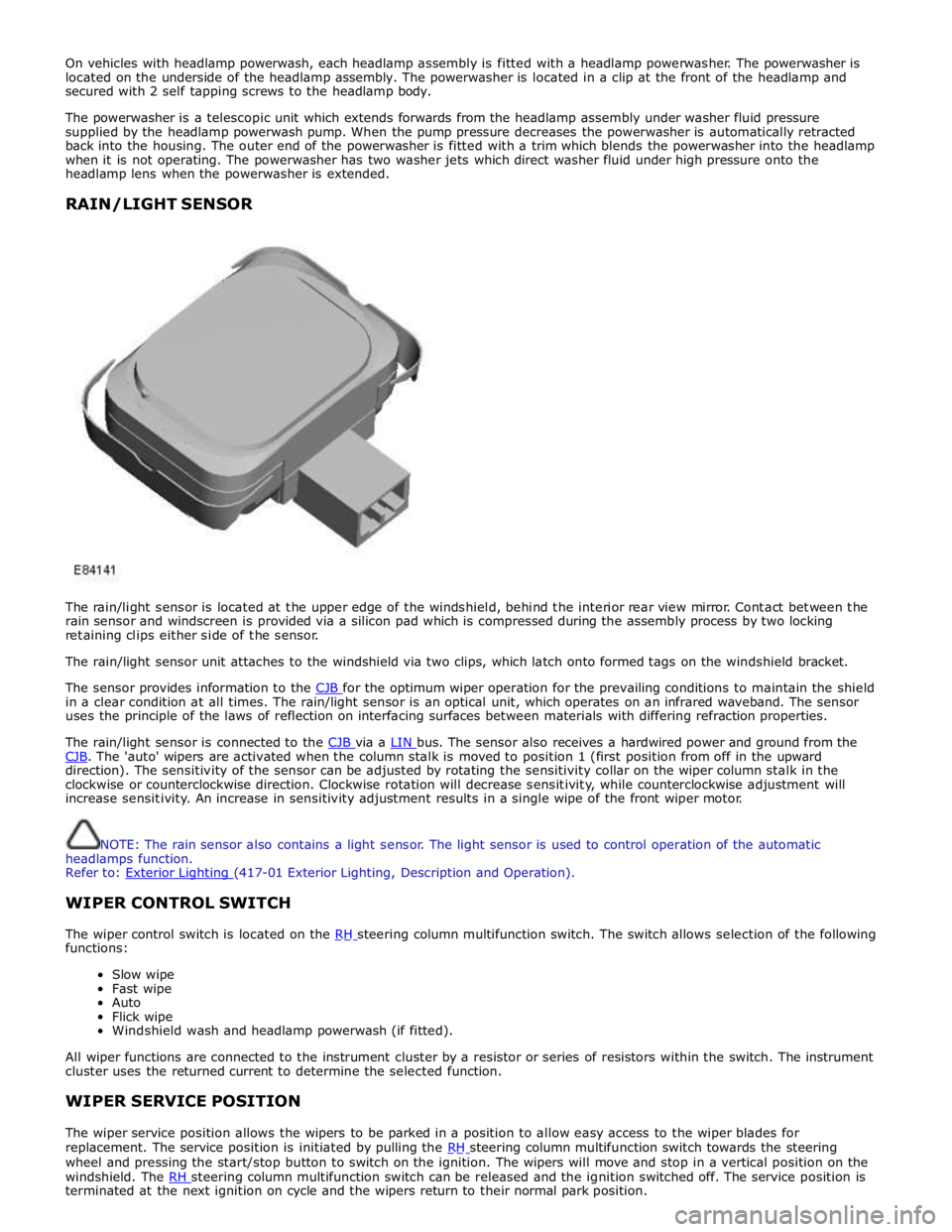
The rain/light sensor is located at the upper edge of the windshield, behind the interior rear view mirror. Contact between the
rain sensor and windscreen is provided via a silicon pad which is compressed during the assembly process by two locking
retaining clips either side of the sensor.
The rain/light sensor unit attaches to the windshield via two clips, which latch onto formed tags on the windshield bracket.
The sensor provides information to the CJB for the optimum wiper operation for the prevailing conditions to maintain the shield in a clear condition at all times. The rain/light sensor is an optical unit, which operates on an infrared waveband. The sensor
uses the principle of the laws of reflection on interfacing surfaces between materials with differing refraction properties.
The rain/light sensor is connected to the CJB via a LIN bus. The sensor also receives a hardwired power and ground from the CJB. The 'auto' wipers are activated when the column stalk is moved to position 1 (first position from off in the upward direction). The sensitivity of the sensor can be adjusted by rotating the sensitivity collar on the wiper column stalk in the
clockwise or counterclockwise direction. Clockwise rotation will decrease sensitivity, while counterclockwise adjustment will
increase sensitivity. An increase in sensitivity adjustment results in a single wipe of the front wiper motor.
NOTE: The rain sensor also contains a light sensor. The light sensor is used to control operation of the automatic
headlamps function.
Refer to: Exterior Lighting (417-01 Exterior Lighting, Description and Operation).
WIPER CONTROL SWITCH
The wiper control switch is located on the RH steering column multifunction switch. The switch allows selection of the following functions:
Slow wipe
Fast wipe
Auto
Flick wipe
Windshield wash and headlamp powerwash (if fitted).
All wiper functions are connected to the instrument cluster by a resistor or series of resistors within the switch. The instrument
cluster uses the returned current to determine the selected function.
WIPER SERVICE POSITION
The wiper service position allows the wipers to be parked in a position to allow easy access to the wiper blades for
replacement. The service position is initiated by pulling the RH steering column multifunction switch towards the steering wheel and pressing the start/stop button to switch on the ignition. The wipers will move and stop in a vertical position on the
windshield. The RH steering column multifunction switch can be released and the ignition switched off. The service position is terminated at the next ignition on cycle and the wipers return to their normal park position.
Page 2608 of 3039

Passenger air bag module retaining nuts 6 - 55 Passenger air bag earth lead retaining bolt 9 - 80 Restraints control module (RCM) retaining nuts 10 - 89 Side air curtain module inflator retaining bolts 9 - 80 Side air curtain module tether straps retaining bolts 9 - 80 Side air bag module retaining nuts 7 - 62 Side impact sensor retaining bolt 10 - 89 Front crash sensor retaining bolt 10 - 89 Clock spring retaining screws 5 - 44
Page 2614 of 3039
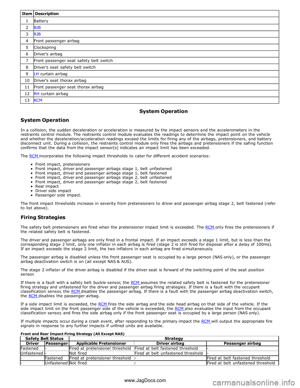
Item Description 1 Battery 2 BJB 3 RJB 4 Front passenger airbag 5 Clockspring 6 Driver's airbag 7 Front passenger seat safety belt switch 8 Driver's seat safety belt switch 9 LH curtain airbag 10 Driver's seat thorax airbag 11 Front passenger seat thorax airbag 12 RH curtain airbag 13 RCM
System Operation System Operation
In a collision, the sudden deceleration or acceleration is measured by the impact sensors and the accelerometers in the
restraints control module. The restraints control module evaluates the readings to determine the impact point on the vehicle
and whether the deceleration/acceleration readings exceed the limits for firing any of the airbags, pretensioners, and battery
disconnect unit. During a collision, the restraints control module only fires the airbags and pretensioners if the safing function
confirms that the data from the impact sensor(s) indicates an impact limit has been exceeded.
The RCM incorporates the following impact thresholds to cater for different accident scenarios: Front impact, pretensioners
Front impact, driver and passenger airbags stage 1, belt unfastened
Front impact, driver and passenger airbags stage 1, belt fastened
Front impact, driver and passenger airbags stage 2, belt unfastened
Front impact, driver and passenger airbags stage 2, belt fastened
Rear impact
Driver side impact
Passenger side impact.
The front impact thresholds increase in severity from pretensioners to driver and passenger airbag stage 2, belt fastened (refer
to list above).
Firing Strategies
The safety belt pretensioners are fired when the pretensioner impact limit is exceeded. The RCM only fires the pretensioners if the related safety belt is fastened.
The driver and passenger airbags are only fired in a frontal impact. If an impact exceeds a stage 1 limit, but is less than the
corresponding stage 2 limit, only one inflator in each airbag is fired (stage 2 is still fired for disposal after a delay of 100ms).
If an impact exceeds the stage 2 limit, the two inflators in each airbag are fired simultaneously.
The passenger airbag is disabled unless the front passenger seat is occupied by a large person (NAS only), or the passenger
airbag deactivation switch is on (all except NAS & AUS).
The stage 2 inflator of the driver airbag is disabled if the driver seat is forward of the switching point of the seat position
sensor.
If there is a fault with a safety belt buckle sensor, the RCM assumes the related safety belt is fastened for the pretensioner firing strategy and unfastened for the driver and passenger airbag firing strategies. If there is a fault with the occupant
classification sensor, the RCM disables the passenger airbag. If there is a fault with the passenger airbag deactivation switch, the RCM disables the passenger airbag.
If a side impact limit is exceeded, the RCM fires the side airbag and the side head airbag on that side of the vehicle. If the side impact limit on the front passenger side of the vehicle is exceeded, the RCM also evaluates the input from the occupant classification sensor, and fires the side airbag only if the front passenger seat is occupied by a large person (NAS only).
If multiple impacts occur during a crash event, after responding to the primary impact the RCM will output the appropriate fire signals in response to any further impacts if unfired units are available.
Front and Rear Impact Firing Strategy (All Except NAS)
Safety Belt Status Strategy Driver Passenger Applicable Pretensioner Driver airbag Passenger airbag Fastened - Fired at pretensioner threshold Fired at belt fastened threshold - Unfastened - Not fired Fired at belt unfastened threshold - - Fastened Fired at pretensioner threshold - Fired at belt fastened threshold - Unfastened Not fired - Fired at belt unfastened threshold www.JagDocs.com