2010 JAGUAR XFR Engine
[x] Cancel search: EnginePage 63 of 3039

Highly flammable, flammable - observe No Smoking policy
Pressurized Equipment
See High Pressure Air, Lubrication and Oil Test Equipment.
Solder
Solders are a mixture of metals such that the melting point of the mixture is below that of the constituent metals (normally
lead and tin). Solder application does not normally give rise to toxic lead fumes, provided a gas/air flame is used.
Oxy-acetylene flames should not be used, as they are much hotter and will cause lead fumes to be produced.
Some fumes may be produced by the application of any flame to surfaces coated with grease etc. and inhalation of these
should be avoided.
Removal of excess solder should be undertaken with care, to make sure that fine lead dust is not produced, which can give
toxic effects if inhaled. Respiratory protection may be necessary.
Solder spillage and filings should be collected and removed promptly to prevent general air contamination by lead.
High standards of personal hygiene are necessary in order to avoid ingestion of lead or inhalation of solder dust from clothing.
Solvents
See also Chemical Materials, Fuels (Kerosene), Fire.
e.g. acetone, white spirit, toluene, xylene, trichloroethane.
Used in cleaning and de-waxing materials, paints, plastics, resins, thinners etc.
Some may be highly flammable or flammable.
Skin contact will degrease the skin and may result in irritation and dermatitis following repeated or prolonged contact. Some
can be absorbed through the skin in toxic or harmful quantities.
Splashes in the eye may cause severe irritation and could lead to loss of vision.
Brief exposure to high concentrations of vapors or mists will cause eye and throat irritation, drowsiness, dizziness, headaches
and, in the worst circumstances, unconsciousness.
Repeated or prolonged exposure to excessive but lower concentrations of vapors or mists, for which there might not be
adequate warning indications, can cause more serious toxic or harmful effects.
Aspiration into the lungs (e.g. through vomiting) is the most serious consequence of swallowing.
Avoid splashes to the skin, eyes and clothing. Wear protective gloves, goggles and clothing if necessary.
Ensure good ventilation when in use, avoid breathing fumes, vapors and spray mists and keep containers tightly sealed. Do not
use in confined spaces.
When spraying materials containing solvents, e.g. paints, adhesive, coatings, use extraction ventilation or personal respiratory
protection in the absence of adequate general ventilation.
Do not apply heat or flame except under specific and detailed manufacturer's instructions.
Sound Insulation
See Fibre Insulation, Foams.
Suspended Loads
CAUTION: Never improvise lifting tackle.
There is always a danger when loads are lifted or suspended. Never work under an unsupported, suspended or raised load e.g.
suspended engine, etc.
Always make sure that lifting equipment such as jacks, hoists, axle stands, slings, etc., are adequate and suitable for the job,
in good condition and regularly maintained.
Transmission Brake Bands
See Asbestos.
Underseal
See Corrosion Protection.
Page 67 of 3039

Do not empty fuel while working in a workshop or a pit
Ensure that working area is well ventilated
Ensure that any work on the fuel system is only carried out by experienced and well qualified maintenance personnel
Ensure that fume extraction equipment is used where appropriate
Fume extraction equipment must be in operation when solvents are used e.g. Trichloroethane, white spirit, sbp3,
methylene chloride, perchlorethylene. Do not smoke in the vicinity of volatile degreasing agents.
Whenever possible, use a ramp or pit whilst working beneath a vehicle, in preference to jacking. Position chocks at the wheels
as well as applying the parking brake. Never rely on a jack alone to support a vehicle. Use axle stands, or blocks carefully
placed at the jacking points, to provide a rigid location. Check that any lifting equipment used has adequate capacity and is
fully serviceable. Ensure that a suitable form of fire extinguisher is conveniently located. When using electrical tools and
equipment, inspect the power lead for damage and check that it is properly earthed. Disconnect the earth (grounded) terminal
of the vehicle battery. Do not disconnect any pipes of the air conditioning refrigeration system unless you are trained and
instructed to do so. A refrigerant is used which can cause blindness if allowed to come into contact with the eyes. Ensure that
adequate ventilation is provided when volatile degreasing agents are being used.
Adhere strictly to handling and safety instructions given on containers and labels. Keep oils and solvents away from naked
flames and other sources of ignition. Do not apply heat in an attempt to free seized nuts or fittings; as well as causing
damage to protective coatings, there is a risk of damage from stray heat to electronic equipment and brake lines. Do not leave
tools, equipment, spilt oil etc. around the work area. Wear protective overalls and use barrier cream when necessary.
Environmental Protection
In some countries it is illegal to pour used oil onto the ground, down sewers or drains, or into water courses. The burning of
used engine oil in small space heaters or boilers is not recommended unless emission control equipment is installed. Dispose
of used oil through authorized waste disposal contractors, to licensed waste disposal sites or to the waste oil reclamation
trade. If in doubt, contact the Local Authority for advice on disposal facilities.
Page 72 of 3039

General Information - Standard Workshop Practices
Description and Operation
Protecting the Vehicle Published: 04-Jul-2014
Always install covers to protect the fenders before commencing work in the engine compartment. Always install the interior
protection kit, wear clean overalls and wash hands or wear gloves before working inside the vehicle. Avoid spilling hydraulic
fluid, antifreeze or battery acid on the paintwork. In the event of spillage, wash off with water immediately. Use polythene
sheets in the luggage compartment to protect carpets. Always use the recommended service tool, or a satisfactory equivalent,
where specified. Protect temporarily exposed screw threads by replacing nuts or installing caps.
Vehicle in Workshop
When working on a vehicle in the workshop always make sure that:
The parking brake is applied or the wheels are securely chocked to prevent the vehicle moving forwards or backwards
If the engine is to be run, there is adequate ventilation, or an extraction hose to remove exhaust fumes is installed
There is adequate room to jack up the vehicle and remove the wheels, if necessary
Fender covers are always installed if any work is to be carried out in the engine compartment
The battery is disconnected if working on the engine, underneath the vehicle, or if the vehicle is jacked up
CAUTION: When electric arc welding on a vehicle, always disconnect the generator wiring to prevent the possibility of a
surge of current causing damage to the internal components of the generator.
If using welding equipment on the vehicle, ensure a suitable fire extinguisher is readily available.
Screw Threads
Damaged nuts, bolts and screws must always be discarded. Attempting to recut or repair damaged threads with a tap
or die impairs the strength and fit of the threads and is not recommended.
NOTES:
During certain repair operations, it may be necessary to remove traces of thread locking agents using a tap. Where this
is necessary, the instruction to do so will appear in the relevant operation and it is essential that a tap of the correct size and
thread is used.
New Taptite bolts when used cut their own threads on the first application.
Some bolts are coated with a thread locking agent and unless stated otherwise, they must not be reused. New bolts
having the same part number as the original must always be installed. When nuts or bolts are to be discarded, the
repair operation and relevant torque chart will include an instruction to that effect. Do not use proprietary thread
locking agents as they may not meet the specification required. See also Encapsulated ('Patched') Bolts and Screws.
Always make sure that replacement nuts and bolts are at least equal in strength to those that they are replacing.
Castellated nuts must not be loosened to accept a split pin except in recommended cases when this forms part of an
adjustment.
Do not allow oil or grease to enter blind holes, the hydraulic action resulting from tightening the bolt or stud can split
the housing and also give a false torque reading.
Always tighten a nut, bolt or screw to the specified torque figure, damaged or corroded threads can give a false torque
reading.
Nut and bolt loosening and tightening sequences, where given, must ALWAYS be followed. Distortion of components or
faulty sealing of joints will result if the sequences are not followed. Where an instruction is given to tighten in stages,
these stages must be adhered to; do not attempt to combine stages particularly where certain stages involve
tightening by degrees.
To check or re-tighten a fixing to a specified torque, first loosen a quarter of a turn, then retighten to the specified
torque figure.
Unless instructed otherwise, do not lubricate bolt or nut threads prior to installing.
Where it is stated that bolts and screws may be reused, the following procedures must be carried out:
Check that threads are undamaged.
Remove all traces of locking agent from the threads.
CAUTION: DO NOT use a wire brush; take care that threads are not damaged.
Make sure that threads are clean and free from oil or grease.
Apply the specified locking agent to the bolt threads.
Page 97 of 3039

7
Visual check 8
Noise check 9
Dispose the specified component 10
Replaced by item 9 (Dispose the specified component) 11
Set the engine speed to the specified value 12
Fully apply the parking brake lever 13
Fully release the parking brake lever 14
Do not dispose of batteries into the waste bin 15
Visual check using a mirror 16
Area/component must be dry Mandatory Protective equipment - Health and safety symbols
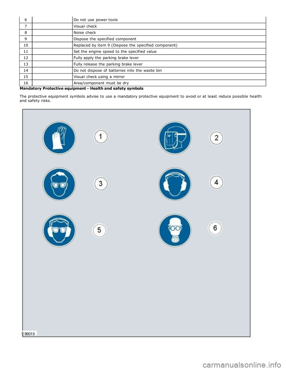
The protective equipment symbols advise to use a mandatory protective equipment to avoid or at least reduce possible health
and safety risks.
Page 103 of 3039

General Information - Road/Roller Testing
Description and Operation Published: 11-May-2011
Road or roller testing may be carried out for various reasons and a procedure detailing pre-test checks, through engine starting
and stopping, pre-driving checks, on-test checks to final checks on completion of the test is given in this section.
Unless complete vehicle performance is being checked, the full road test procedure need not be carried out. Instead, those
items particularly relevant to the system/s being checked can be extracted.
Pre - Test Checks
WARNING: If the brake system hydraulic fluid level is low, pedal travel is excessive or a hydraulic leak is found, do not
attempt to road test the vehicle until the reason for the low fluid level, excessive pedal travel or hydraulic leak is found and
rectified.
It is suggested that pre-test checks, and functional tests of those systems/circuits which affect the safe and legal operations
of the vehicle, such as brakes, lights and steering, should always be carried out before the road or roller test.
Engine oil level
Engine coolant level
Tires, for correct pressure, compatible types and tread patterns, and wear within limits
There is sufficient fuel in the tank to complete the test
All around the engine, transmission and under the vehicle for oil, coolant, hydraulic and fuel leaks. Make a note of any
apparent leaks and wipe off the surrounding areas to make it easier to identify the extent of the leak on completion of
the test
Starting the Engine
CAUTION: On initial drive away from cold and within the first 1.5 km (1 mile), do not depress accelerator pedal beyond
half travel until the vehicle has attained a minimum speed of 25 km/h (15 miles/h). Never operate at high engine speed or
with the accelerator pedal at full travel whilst the engine is cold.
With the ignition switched off, check:
The parking brake is applied
The transmission selector lever is in Park
All instrument gauges (except fuel gauge) read zero
With the ignition switched on, check:
Ignition controlled warning lamps come on
Engine coolant temperature gauge registers a reading compatible with the engine coolant temperature
Fuel gauge registers a reading appropriate to the fuel level in the tank
The operation of the parking brake and brake fluid level warning lamps
On Road or Roller Test Check:
CAUTION: If road testing, check the brake operation while still travelling at low speed before continuing with the test. If
the brakes pull to one side, or appear to be otherwise faulty, do not continue with the road test until the fault has been found
and rectified.
Initial gear engagement is smooth
Parking brake control operates smoothly and the parking brake releases quickly and completely
Transmission takes up the drive smoothly, without judder
The engine power output is satisfactory, full power is achieved, acceleration is smooth and pedal operation not stiff or
heavy, and engine speed returns to idle correctly
There is no excessive or abnormally colored smoke from the engine under normal driving, heavy load or overrun
conditions
Steering operation, including power steering, is smooth, accurate, not excessively heavy or with excessive free play or
vibration. Does not pull to one side and self centres smoothly after cornering
Speedometer, oil pressure warning lamp, coolant temperature gauge and tachometer register the correct readings or
operate correctly
Switches and controls operate smoothly and positively, warning lamps operate correctly and the direction indicator
control self cancels when the steering is returned to the straight ahead position
Heating and ventilation systems work correctly and effectively
Brake operation and efficiency
Brake Testing
WARNING: When brake testing, avoid breathing the smoke or fumes from hot brakes, this may contain asbestos dust
which is hazardous to health, see Health and Safety Precautions.
Page 117 of 3039

DTC Description Possible Causes Action Sensor or Left Rear
Vertical Acceleration
Sensor or Right Rear
Vertical Acceleration
Sensor supply partial
short to other circuit
or ground
Left Front Vertical
Acceleration Sensor or
Right Front Vertical
Acceleration Sensor or
Left Rear Vertical
Acceleration Sensor or
Right Rear Vertical
Acceleration Sensor
internal failure
Internal control
module failure U0001-88
High speed CAN
communication
bus - Bus off
Lost Communication
With Engine Control
Module (ECM) (CAN
Bus circuit fault)
Check Engine Control Module for stored DTCs. Refer to the
electrical circuit diagrams and check CAN Bus circuit for faults,
check CAN circuits for open circuits or shorts to power, ground
or other circuits U0100-00
Lost
Communication
With ECM/PCM A
- No sub type
information
Missing message from
ECM
Check Engine Control Module for stored DTCs. Refer to the
electrical circuit diagrams and check CAN Bus for circuit fault U0101-00
Lost
Communication
with TCM - No
sub type
information
Lost Communication
with Transmission
control module (TCM)
(CAN Bus circuit fault)
Check Transmission Control Module for stored DTCs. Refer to
the electrical circuit diagrams and check CAN Bus for circuit
fault U0103-00
Lost
Communication
With Gear Shift
Control Module
A - No sub type
information
Lost Communication
With Gear Shift
Module (GSM) (CAN
Bus circuit fault)
Check Gear Shift Module for stored DTCs. Refer to the
electrical circuit diagrams and check Can Bus for circuit faults U0121-00
Lost
Communication
With Anti-Lock
Brake System
(ABS) Control
Module - No sub type information
Lost Communication
With Anti-Lock Brake
System (ABS) Control
Module (CAN Bus
circuit fault)
Check Anti lock Brake System Control Module for stored DTCs.
Refer to the electrical circuit diagrams and check Can Bus
circuit to Anti lock Brake System Control Module for circuit
faults U0132-00 Lost
Lost Communication
Check Air Suspension Control Module for stored DTCs. Refer to Communication With Suspension With Air Suspension the electrical circuit diagrams and check CAN Bus circuit to Air Control Module Control Module (CAN Suspension Control Module for circuit faults A - No sub type Bus circuit fault information U0136-00
Lost
Communication
With Differential
Control Module -
Rear - No sub type information
Lost Communication
With Rear Differential
Control Module (CAN
Bus circuit fault)
Check Rear Differential Control Module for stored DTCs. Refer
to the electrical circuit diagrams and check Can Bus circuit to
Rear Differential Control Module for circuit faults U0140-00
Lost
Communication
With Body
Control Module -
No sub type
information
Lost Communication
With Body Control
Module (Front Smart
Junction Box) (CAN
Bus circuit fault)
Check Body Control Module for stored DTCs. Refer to the
electrical circuit diagrams and check CAN Bus circuit to Body
Control Module for faults U0142-00
Lost
Communication
With Body
Control Module
B - No sub type
information
Lost Communication
with rear smart
junction box (CAN Bus
circuit fault)
Check Rear Smart Junction Box for stored DTCs. Refer to the
electrical circuit diagrams and check Can Bus circuit to Rear
Smart Junction Box for faults U0155-00
Lost
Communication
With Instrument
Panel Cluster
Lost Communication
With Instrument Panel
Cluster (IPC) Control
Check Instrument Panel Cluster for stored DTCs. Refer to the
electrical circuit diagrams and check CAN Bus to Instrument
Panel Cluster for circuit fault
Page 118 of 3039

DTC Description Possible Causes Action (IPC) Control
Module - No sub
type information Module (CAN bus
circuit fault) U0300-00
Internal control
module software
incompatibility -
No sub type
information
CAN master
configuration ID
incorrect
Check Front Smart Junction Box vehicle configuration file,
check part number of adaptive damping control module U0401-68
Invalid Data
Received from
ECM/PCM A -
Event
information
Invalid Data Received
from Engine Control
Module
Check Engine Control Module for DTCs. Refer to the relevant
DTC index U0402-68
Invalid Data
Received from TCM - Event
information
Invalid Data Received
from Transmission
control module
Check for Transmission Control Module DTCs. Refer to relevant
DTC index U0404-68
Invalid Data
Received from
Gear Shift
Control Module
A - Event
information
Invalid data received
from gear shift control
module
Check Gear Shift Control Module for DTCs. Refer to the
relevant DTC index U0415-68
Invalid Data
Received From
Anti-Lock Brake
System (ABS)
Control Module -
Event
information
Invalid Data Received
From Anti-Lock Brake
System (ABS) Control
Module
Check for Anti lock Brake System DTCs. Refer to the relevant
DTC index U0421-68
Invalid Data
Received from
Suspension
Control Module
A - Event
information
Invalid Data Received
From Air Suspension
Control Module
Check Air Suspension Control Module for stored DTCs. Refer to
the relevant DTC index U0422-68
Invalid Data
Received From
Body Control
Module - Event
information
Invalid Data Received
From Body Control
Module (Front Smart
Junction Box)
Check Body Control Module (Front Smart Junction Box) for
stored DTCs. Refer to the relevant DTC index U0437-68
Invalid Data
Received From
Differential
Control Module -
Rear - Event
information
Invalid Data Received
From Rear Differential
Control Module
Check Rear Differential Control Module for stored DTCs. Refer
to the relevant DTC index U0443-68
Invalid Data
Received From
Body Control
Module B -
Event
information
Invalid Data Received
From body control
module B (Rear Smart
Junction Box)
Check rear smart junction box for DTCs and refer to relevant
DTC index U1A14-00 CAN
initialization
failure - No sub type information
CAN network harness
short, disconnected
Refer to circuit diagrams and check CAN Bus circuit for fault
(short to power, ground or open circuit) U2100-00
Initial
Configuration
Not Complete -
No sub type
information
Car Configuration
Data not loaded (New
Body Control Module
(Front Smart Junction
Box) fitted to vehicle
and not initialized)
Internal Body Control
Module (Front Smart
Junction Box) failure
Install car config to Front Smart Junction Box. Clear DTC and
retest systems U2101-00
Control Module
Configuration
Incompatible -
No sub type
information
Car Configuration
Data transmitted over
CAN does not match
adaptive damping
control module
internal config
Carry out the new module software installation procedure
Page 120 of 3039

Published: 17-Apr-2014
General Information - Diagnostic Trouble Code (DTC) Index DTC: Anti-Lock Braking System (ABS)
Description and Operation
Anti-Lock Braking System (ABS)
CAUTION: Diagnosis by substitution from a donor vehicle is NOT acceptable. Substitution of control modules does not
guarantee confirmation of a fault, and may also cause additional faults in the vehicle being tested and/or the donor vehicle
NOTES:
If the control module or a component is suspect and the vehicle remains under manufacturer warranty, refer to the
warranty policy and procedures manual, or determine if any prior approval programme is in operation, prior to the installation
of a new module/component
Generic scan tools may not read the codes listed, or may read only 5-digit codes. Match the 5 digits from the scan tool to
the first 5 digits of the 7-digit code listed to identify the fault (the last 2 digits give extra information read by the
manufacturer-approved diagnostic system)
When performing voltage or resistance tests, always use a digital multimeter accurate to three decimal places and with a
current calibration certificate. When testing resistance, always take the resistance of the digital multimeter leads into account
Check and rectify basic faults before beginning diagnostic routines involving pinpoint tests
Inspect connectors for signs of water ingress, and pins for damage and/or corrosion
If diagnostic trouble codes are recorded and, after performing the pinpoint tests, a fault is not present, an intermittent
concern may be the cause. Always check for loose connections and corroded terminals
Where an 'on demand self-test' is referred to, this can be accessed via the 'diagnostic trouble code monitor' tab on the
manufacturers approved diagnostic system
Check DDW for open campaigns. Refer to the corresponding bulletins and SSMs which may be valid for the specific
customer complaint and carry out the recommendations as required
The table below lists all Diagnostic Trouble Codes (DTCs) that could be logged in the anti-lock braking system module, for
additional diagnosis and testing information refer to the relevant Diagnosis and Testing Section.
For additional information, refer to: Anti-Lock Control - Stability Assist (206-09 Anti-Lock Control - Stability Assist, Diagnosis
and Testing).
DTC Description Possible Causes Action C0021-09
Brake Booster
Performance -
Component Failures
No vacuum available from
engine due to split/leaking
hose etc
Brake booster servo has
failed due to lack of vacuum
Check integrity of brake booster vacuum hose.
Check and install a new brake booster as required C0030-38
Left Front Tone
Wheel - Signal
frequency incorrect
Left front magnetic pulse
ring damaged/contaminated
Incorrect component
installed
Sensor internal fault
Check the left front magnetic pulse ring for damage
or contamination. Clean or replace as required. If no
damage/contamination found, suspect wheel speed
sensor. Refer to the Warranty Policy and Procedures
manual if a module/component is suspect. To
validate the repair and extinguish the lamps, the
vehicle needs to be driven above 9mph/15kph for
more than 10 seconds C0031-12
Left Front Wheel
Speed Sensor -
Short to battery
Electrical wiring harness
fault
Sensor internal fault
Refer to the electrical circuit diagrams and check the
wheel speed sensor circuit for short to power. Repair
harness as required. If no harness fault found,
suspect wheel speed sensor. Refer to the Warranty
Policy and Procedures manual if a www.JagDocs.com