2010 JAGUAR XFR Transmission
[x] Cancel search: TransmissionPage 1945 of 3039
player is only compatible with standard CD's. All other versions of CD player are compatible with standard CDs and CDs with MP3 or WMA (windows media audio) files.
A portable audio module allows for the connection of a range of portable audio devices to the car’s audio system. The portable
audio module is controlled through the IAM (integrated audio module) and Touch-screen with play back through the car’s
speaker system. The introduction of this system allows the user to import their personal portable media player to interface
with the car, including iPod and other MP3 players, or USB mass storage devices such as memory sticks. MP3 players can also
be controlled through the Touch-screen if they are configured as mass storage devices. Details of how to do this will be
contained in the manufacturers instructions.
The chosen audio device can be plugged into the car using an interface panel located in the floor console between the front
seats. The interface includes a 3.5mm auxiliary jack-plug socket, a 12-volt power supply, a dedicated iPod connector with
charging function, plus a USB2 connector which allows connectivity for a wide variety of USB devices. The USB port also
provides a charging function although it does not support a USB hub. The maximum charging current supplied is 500ma. The
user can connect an iPod and USB device at the same time, changing the source via the Touch-screen. The non selected source
will still charge.
The Jaguar Sound System is the basic audio system which comprises of an IAM (integrated audio module) with no external
amplifier and 8 speakers.
The Jaguar 320W Premium Sound System has the addition of an AUD 8 power amplifier and a 9 speaker system.
The Bowers & Wilkins 440w Surround Sound System additions include an AUD 12 power amplifier, a Dolby Pro-Logic 2 7.1
Surround Sound System, and 14 speakers.
DAB (digital audio broadcasting) is available for most European markets and gives access to digital radio channels for better
sound quality and enhanced functionality depending on local service availability. The DAB (digital audio broadcasting) module
is located in the luggage compartment. The system receives reception signals from the following sources to ensure optimum
signal strength.
DAB band L antenna located in the roof pod antenna module
DAB band III antenna located in the heated rear window.
For NAS vehicles the digital format adopted is satellite radio which specifically links to the Sirius network. The system operates
in the S-band frequency range, and as a result of the use of satellite transmission, has the ability to provide CD quality audio broadcasts over very large areas (typically continents). The satellite radio receiver is located in the luggage compartment. The
system receives reception signals from the satellite radio antenna located in the roof pod module.
Primary user control of the audio system is via the ICP (integrated control panel) and the Touch-screen which are located in the
center of the instrument panel. Control signals from the ICP (integrated control panel) are relayed on the medium speed CAN
(controller area network) bus to the ICM (information control module). The ICM (information control module) relays the control
signals to the rest of the audio system on the MOST (media oriented systems transport) ring. The ICM (information control
module) is the timing master for the MOST (media oriented systems transport) ring and also hosts a gateway function between
the medium speed CAN bus and the MOST (media oriented systems transport) ring. Audio output signals on the Jaguar 320W Premium Sound System and Bowers & Wilkins 440W Surround Sound System are sent on the MOST (media oriented systems
transport) ring from the IAM (integrated audio module) to the power amplifier for speaker output. www.JagDocs.com
Page 1957 of 3039
NOTE: When the vehicle DAB radio is first used the system will not receive any digital stations until the auto-tune
function has been completed.
Digital radio channels are organized into groups called ensembles (also known as multiplexes). Some individual channels may
also provide a number of subchannels. For example, if several sports events are being held simultaneously, the channel may
temporarily choose to broadcast each different event on a separate subchannel.
DAB is broadcast across Europe, Canada and parts of Asia. System transmission is via a terrestrial network, on two separate
broadcasting bands:
DAB band-L
DAB band III
The DAB system requires additional components to be added to the audio system. DAB antennas and a receiver are fitted to
allow reception of the service.
Operation of the DAB system is the same as the radio operation with selections made through the touch-screen and ICP to
access and navigate the system functions.
The DAB receiver is a dedicated tuner which is controlled by the ICM on the MOST ring. The receiver processes the signals from
the DAB antennas. Information is transmitted on the MOST ring and processed by the ICM. The processed information is sent
out to the power amplifier or IAM (with internal amplifier) and broadcast through the speaker system.
No configuration procedure is required if the DAB receiver is replaced. Calibration of the DAB receiver using the Jaguar
approved diagnostic equipment enables updates to be downloaded as new technology becomes available or any fault concerns
require software updates.
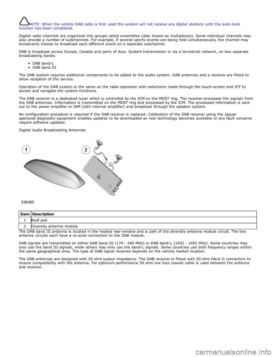
Digital Audio Broadcasting Antennas
Item Description 1 Roof pod 2 Diversity antenna module The DAB band III antenna is located in the heated rear window and is part of the diversity antenna module circuit. The two
antenna circuits each have a co-axial connection to the DAB module.
DAB signals are transmitted on either DAB band III (174 - 240 MHz) or DAB band-L (1452 - 1492 MHz). Some countries may
only use the band III signals, while others may only use the band-L signals. Some countries use both frequency ranges within
the same geographical area. The type of DAB signal received depends on the vehicle market location.
The DAB antennas are designed with 50 ohm output impedance. The DAB receiver is fitted with 50 ohm fakra II connectors to
ensure compatibility with the antenna. For optimum performance 50 ohm low loss coaxial cable is used between the antenna
and receiver.
Page 1958 of 3039
The digital radio format adopted for NAS vehicles is satellite radio. Satellite service providers transmit a signal from their
up-link facility (which is the original point of transmission of data, voice or other information through an antenna system) to a
satellite where the signal is then down linked to both the terrestrial repeater network and the individual satellite car radios.
The radio switches between the satellite signal and the repeater network signal depending on the strength of the signal at any
given time.
The Sirius satellite system comprises:
Satellites
Ground repeaters
Up-link ground stations
Radio receiver systems
The Sirius satellite radio system uses three satellites on an inclined elliptical orbit. This ensures that each satellite spends
approximately 16 hours a day over the continent of the USA, with at least one satellite over the country at any one time.
The satellites beam their signals down to the ground where the signal is picked up by receivers or is transmitted to repeater
stations to cover built up areas where the signal is obscured. The satellite service comprises over 100 channels of digital
entertainment which is provided by subscription requiring a monthly payment.
Operation of the satellite radio system is the same as the radio operations with selections made through the Touch-screen and
ICP to access and navigate the system functions.
The satellite radio receiver is a dedicated tuner which is controlled by the ICM on the MOST ring. The receiver filters the
signals from the satellite radio antenna. Information is transmitted on the MOST ring and processed by the ICM. The processed
information is sent out to the power amplifier or IAM (with internal amplifier) and broadcast through the speaker system.
No configuration procedure is required if the satellite radio receiver is replaced. Calibration of the satellite radio receiver using
the Jaguar approved diagnostic equipment enables updates to be downloaded as new technology becomes available or any
fault concerns require software updates.
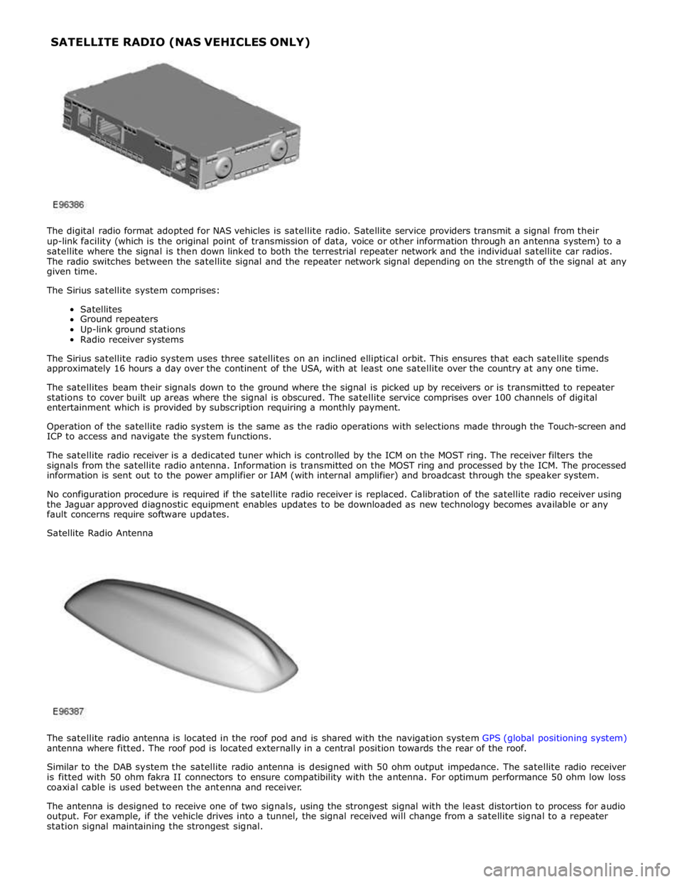
Satellite Radio Antenna
The satellite radio antenna is located in the roof pod and is shared with the navigation system GPS (global positioning system)
antenna where fitted. The roof pod is located externally in a central position towards the rear of the roof.
Similar to the DAB system the satellite radio antenna is designed with 50 ohm output impedance. The satellite radio receiver
is fitted with 50 ohm fakra II connectors to ensure compatibility with the antenna. For optimum performance 50 ohm low loss
coaxial cable is used between the antenna and receiver.
The antenna is designed to receive one of two signals, using the strongest signal with the least distortion to process for audio
output. For example, if the vehicle drives into a tunnel, the signal received will change from a satellite signal to a repeater
station signal maintaining the strongest signal. SATELLITE RADIO (NAS VEHICLES ONLY)
Page 1977 of 3039
In addition to the standard navigation system there are two market dependant systems that supply extra information to the
navigation system and the driver. These are:
TMC (traffic message channel) (Europe only)
VICS (vehicle information and communication system) (Japan only)
The TMC (traffic message channel) is a function of the FM (frequency modulation)RDS (radio data system). The system
broadcasts real-time traffic and weather information. Data messages are received and decoded by the TMC (traffic message
channel) integral receiver and processed by the navigation computer. TMC (traffic message channel) messages can be filtered
by the navigation computer so that only those relevant to the current journey are displayed, allowing the navigation system to
offer dynamic route guidance - alerting the driver of a problem on the planned route and calculating an alternative route to
avoid the incident. All TMC (traffic message channel) events on the map can be viewed not just the ones on the calculated
route.
TMC (traffic message channel) traffic information systems conform to a global standard that has been adopted by traffic data
gatherers, information service providers, broadcasters and vehicle/receiver manufacturers.
All TMC (traffic message channel) receivers use the same list of event codes, while the location database (on the map disc)
contains both a country-specific set of location codes for the strategic European road network.
TMC (traffic message channel) traffic data is currently broadcast in many European countries.
The VICS (vehicle information and communication system) is broadcast in the Japanese market.
The VICS (vehicle information and communication system) supplies information to enable the navigation computer to re-route
the navigation guidance or to inform the vehicle driver of traffic conditions in the vehicles vicinity. Information is provided to
the system through 3 routes:
RF (radio frequency) transmission
Infra-red transmission
FM multiplex transmissions
The RF (radio frequency) transmissions are generally transmitted from road side beacons mainly on expressways. The
information transmitted is as follows:
Traffic congestion
Travel time to next intersection
Traffic conditions in surrounding areas and expressway turn offs
Traffic accidents
Speed limits
Lane regulations
Tire change
Parking availability at expressway service areas and parking areas
Infra-Red transmissions are transmitted from road side beacons on major trunk roads. The information transmitted is:
Traffic congestion and travel time
Traffic accidents
Breakdowns
Road works restrictions
Parking availability
FM transmissions are broadcast as part of the FM multiplex broadcasting system from NHK FM stations. Information transmitted is:
Traffic congestion and travel time for wide areas
Traffic accidents, road works, speed limits and lane restrictions for a wide area
Parking availability information
The traffic data is split from the normal FM transmissions by the diversity antenna module.
Selection of 'Navigation' on the Touch-screen home menu and subsequent sub-menu selection sends a control request signal to
the navigation computer on the MOST (media orientated systems transport) ring. The requested control information is
processed by the navigation computer.
If voice guidance is operational the voice signal information is relayed from the navigation computer on the MOST (media
orientated systems transport) ring to either the IAM (integrated audio unit) or Power Amplifier, dependant on equipment level,
for output on the speaker system. The navigation audio output is through the front speakers whilst the background audio, for
example radio or CD (compact disc), is played at a reduced volume on the rear speakers.
The GPS signal is available to the navigation system at all times when the vehicle ignition is switched on.
Navigation user voice commands are made using the JaguarVoice system. The ICM (information control module) processes the
analogue signal from the JaguarVoice switch into a digital signal. The digital signal is passed from the ICM (information control
module) onto the MOST (media orientated systems transport) system to the JaguarVoice control unit which is integral with the
navigation computer.
The navigation computer sends an instruction via the MOST (media orientated systems transport) ring to the IAM (integrated
audio module) to turn on the microphone facility.
The microphone is hardwired to the IAM (integrated audio module). The spoken voice command signals are relayed from the
IAM (integrated audio module) via the MOST (media orientated systems transport) ring to the navigation computer for
Page 2001 of 3039
Published: 11-May-2011
Information and Entertainment System - Steering Wheel Audio Controls
Removal and Installation
Removal
NOTE: Removal steps in this procedure may contain installation details.
1. Make the SRS system safe.
Refer to: Standard Workshop Practices (100-00 General Information, Description and Operation).
2. Refer to: Driver Air Bag Module (501-20B Supplemental Restraint System, Removal and Installation).
3. Refer to: Upshift Paddle Switch (307-05A Automatic Transmission/Transaxle External Controls - V6 3.0L Petrol, Removal and
Installation).
4. Refer to: Downshift Paddle Switch (307-05A Automatic Transmission/Transaxle External Controls - V6 3.0L Petrol, Removal and
Installation).
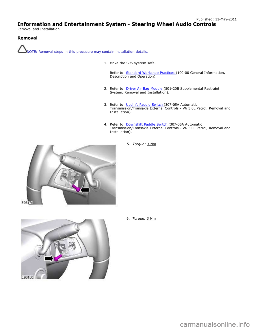
5. Torque: 3 Nm 6. Torque: 3 Nm
Page 2033 of 3039
Halogen Low/high Beam Headlamp
The halogen low/high beam headlamp uses a projector lens, similar to the xenon headlamp. The projector module comprises
an ellipsoidal lens and a reflector. The projector reflector collects the light produced by the halogen bulb and projects the light
into a focal plane containing a shield. The contour of the shield is projected onto the road by the lens. The low/high beam
bulbs are quartz halogen and are retained in the headlamp unit with conventional wire retaining clips.
A tourist lever mechanism is located on the right hand side of the projector module. This mechanism moves a flap to blank off
a portion of the beam spread to enable the vehicle to be driven in opposite drive hand markets without applying blanking
decals to the headlamp lens. The beam is changed by removing the access cover at the rear of the lamp assembly and moving
a small lever located near the bulb holder, at the side of the projector.
Halogen High Beam Headlamp - Xenon and Halogen
The xenon and halogen headlamps use a complex surface reflector for the halogen fill in high beam lamp only lighting unit,
which is of the same design on both headlamp types. This type of reflector has the reflector divided into separate parabolic
segments, with each segment having a different focal length.
The high beam headlamp bulbs are quartz halogen and are retained in the headlamp unit with conventional wire retaining
clips.
Cornering Lamps
NOTE: The cornering lamps are not fitted to NAS vehicles.
The cornering lamps are an optional feature designed to illuminate the direction of travel when cornering at low speeds. The
design of the lens projects a spread of light from the vehicle at approximately 45 degrees to the vehicle axis. The cornering
lamp is incorporated into the headlamp assembly and shares the same housing as the low beam headlamp. The cornering lamp
uses a 35W Halogen H8 bulb which is permanently located in an integral holder which is connected on the headlamp housing.
The holder is located in an aperture in the headlamp housing and rotated to lock. The bulb is accessible via a removable cover
on the base of the headlamp housing.
The cornering lamps are controlled by the LH steering column multifunction switch with the lighting control switch in the headlamp position and the ignition in power mode 6. The cornering lamps are supplied power via the ignition circuit to ensure
that they do not function with the headlamp delay feature. The cornering lamps are deactivated if the vehicle speed exceeds
25 mph (40 km/h). Only one cornering lamp will illuminate at any one time. If the left hand turn signal indicators are selected
on, the left hand cornering lamp will be illuminated and vice versa, providing the vehicle speed and lighting control switch
positions are correct.
Static Bending Lamps
NOTE: The static bending lamps are not fitted to NAS vehicles.
The static bending lamps are designed to illuminate the direction of travel when cornering at low speeds. The static bending
lamp functionality, which is controlled by the CJB and the headlamp leveling module, operates using inputs from the steering angle sensor and vehicle speed information from the ABS (anti-lock brake system) module. The static bending lamp is
incorporated into the headlamp assembly and shares the same housing as the low beam headlamp. The design of the lens
projects a spread of light from the vehicle at approximately 45 degrees to the vehicle axis. The static bending lamp uses a
35W Halogen H8 bulb which locates in a holder which is connected via wires to the main connector on the headlamp housing.
The holder is located in an aperture in the headlamp housing and rotated to lock. The bulb is accessible via a removable cover
at the rear of the headlamp housing.
The static bending lamps operate with a steering angle sensor CAN bus signal which is received by the CJB. The CJB monitors this signal and vehicle speed and activates the static bending lamp bulb. When the operation parameters of the lamp are
reached, the CJB fades the static bending lamp bulb on using a PWM (pulse width modulation) voltage over a period of approximately 2 seconds. When the lamp is switched off, the CJB fades the bulb off by decreasing the PWM voltage in a linear manner depending on steering angle and vehicle speed. The cornering lamps can only be active for a maximum of 3 minutes.
NOTE: Static bending lamps only operate when the transmission is in DRIVE or in SPORT.
Turn Signal Indicators
The turn signal indicator lamp is incorporated into the outer part of the headlamp assembly. The turn signal indicator lamp
uses a PY21W bayonet orange colored bulb in ROW markets, a S8W 27/7W wedge bulb is used in NAS markets. The bulb is
fitted into a holder which connects with contacts in the headlamp housing. The holder is fitted into an aperture in the
headlamp housing and rotated to lock into position.
When active, the turn signal indicator lamps will flash at a frequency cycle of 380ms on and 380ms off. If a bulb fails, the
remaining turn signal lamps bulbs continue to flash at normal speed. The turn signal indicators in the instrument cluster will
flash at double speed to indicate the bulb failure to the driver.
Side Lamps
The side lamp is located between the headlamp projector module and the high bean headlamp. The side lamp uses a W5W
wedge fitting bulb which locates in a holder which connected via wires to the main connector on the headlamp housing. The
holder is a push fit into a receptacle in the headlamp housing. The bulb is accessible by removal of the inner cover on the rear
of the headlamp housing. Access to the bulb requires removal of the headlamp from the vehicle. The side lamps are operated
by selecting side lamps or headlamps on the lighting control switch. The side lamps are functional at all times and are
Page 2066 of 3039
Published: 11-May-2011
Daytime Running Lamps (DRL) - Daytime Running Lamps (DRL) - System
Operation and Component Description
Description and Operation
CENTRAL JUNCTION BOX (CJB) System Operation
The CJB (central junction box) controls the operation of the DRL (daytime running lamps). The DRL are activated once the CJB detects an ignition on power mode 6 signal.
The CJB also monitors the lighting control switch and the auto lamps feature and overrides the DRL if required.
DAYTIME RUNNING LAMPS - CANADA Component Description
The DRL for this market use full intensity low beam headlamps. The side marker lamps, tail lamps and license plate lamps will be on, but instrument cluster illumination will be off. DRL are active when the following parameters are met:
PARK is not selected on the electronic transmission selector
Electronic Parking Brake (EPB) is off
Power mode 6 (ignition on) detected by the CJB The CJB receives an engine running signal The lighting control switch is in the off or side lamps position.
NOTES:
If the lighting control switch is moved to the headlamp position, DRL are deactivated and normal side lamp and headlamp functionality is operational.
When DRL are active, the headlamp flash function using the left hand steering column multifunction switch will operate normally.
The high beam headlamp function using the left hand steering column stalk switch will be deactivated. When the transmission
is in PARK, DRL are turned off. This is to reduce battery discharge during long periods of engine idling in cold climate conditions. When the electronic transmission selector is moved from the PARK position, normal DRL functionality is restored.
DAYTIME RUNNING LAMPS - DENMARK, HOLLAND, NORWAY, SWEDEN, FINLAND AND POLAND
NOTE: DRL for Poland is on vehicles from 2008MY.
DRL for these markets use full intensity low beam headlamps. Side lamps and license plate lamps will be on, but instrument cluster illumination will be off. DRL are active when the following parameters are met:
Power mode 6 (ignition on) detected by the CJB The CJB receives an engine running signal The lighting control switch is in the off position.
NOTE: When DRL are active, the headlamp flash function using the left hand steering column multifunction switch will operate normally. The high beam headlamp function using the left hand steering column stalk switch will be deactivated.
If the lighting control switch is moved to the side lamp or headlamp positions, DRL are deactivated and normal side lamp and headlamp functionality is operational.
AUTOMATIC HEADLAMPS
On vehicles fitted with the automatic headlamps feature, DRL are overridden if the lighting control switch is in the 'Auto' position and the CJB receives a signal from the rain/light sensor to activate the exterior lights.
When the CJB receives a signal to de-activate the automatic headlamps feature the DRL function is restored providing the parameters for DRL activation are met.
Page 2067 of 3039
Published: 11-May-2011
Module Communications Network - Communications Network - Overview
Description and Operation
OVERVIEW
A number of different types of communication network are incorporated into the vehicle wiring harnesses for the transmission
of commands and information between control modules. The configuration installed on a particular vehicle depends on the
model and equipment level.
NOTE: The control diagrams shown later in this section are schematics reflecting communications networks fitted to LH
(left-hand) vehicles only. For detailed layouts of the various communications networks fitted to LHD (left-hand drive) and RHD
(right-hand drive) vehicles, refer to the Electrical Guide.
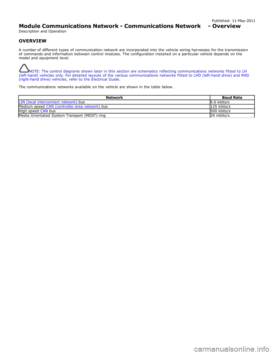
The communications networks available on the vehicle are shown in the table below.
Network Baud Rate LIN (local interconnect network) bus 9.6 kbits/s Medium speed CAN (controller area network) bus 125 kbits/s High speed CAN bus 500 kbits/s Media Orientated System Transport (MOST) ring 24 mbits/s