2010 JAGUAR XFR Transmission
[x] Cancel search: TransmissionPage 2707 of 3039
For instance, the crumple zones absorb the bulk of the impact energy. If any unprofessional repair techniques or
methods are used in these areas then this can pose a fundamental threat to vehicle safety.
Hidden damage
As well as looking at external indicators like flaked off paint, it is vital to check for hidden body damage or deformation
that is not visible from the outside. Large attached parts like bumpers and inner fenders often need to be removed to
allow accurate assessment of damage to underlying body parts.
Gap dimensions
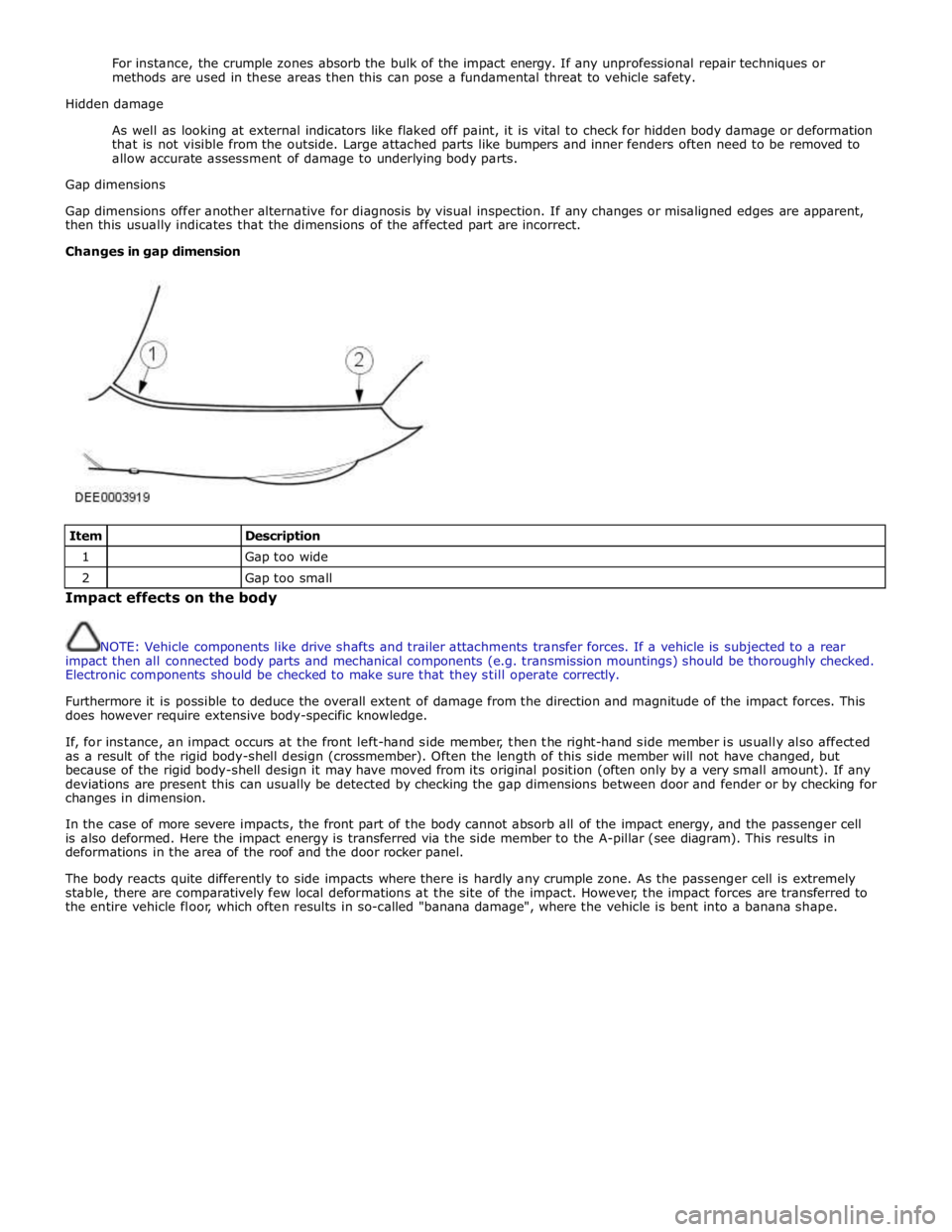
Gap dimensions offer another alternative for diagnosis by visual inspection. If any changes or misaligned edges are apparent,
then this usually indicates that the dimensions of the affected part are incorrect.
Changes in gap dimension
Item
Description 1
Gap too wide 2
Gap too small Impact effects on the body
NOTE: Vehicle components like drive shafts and trailer attachments transfer forces. If a vehicle is subjected to a rear
impact then all connected body parts and mechanical components (e.g. transmission mountings) should be thoroughly checked.
Electronic components should be checked to make sure that they still operate correctly.
Furthermore it is possible to deduce the overall extent of damage from the direction and magnitude of the impact forces. This
does however require extensive body-specific knowledge.
If, for instance, an impact occurs at the front left-hand side member, then the right-hand side member is usually also affected
as a result of the rigid body-shell design (crossmember). Often the length of this side member will not have changed, but
because of the rigid body-shell design it may have moved from its original position (often only by a very small amount). If any
deviations are present this can usually be detected by checking the gap dimensions between door and fender or by checking for
changes in dimension.
In the case of more severe impacts, the front part of the body cannot absorb all of the impact energy, and the passenger cell
is also deformed. Here the impact energy is transferred via the side member to the A-pillar (see diagram). This results in
deformations in the area of the roof and the door rocker panel.
The body reacts quite differently to side impacts where there is hardly any crumple zone. As the passenger cell is extremely
stable, there are comparatively few local deformations at the site of the impact. However, the impact forces are transferred to
the entire vehicle floor, which often results in so-called "banana damage", where the vehicle is bent into a banana shape.
Page 2738 of 3039
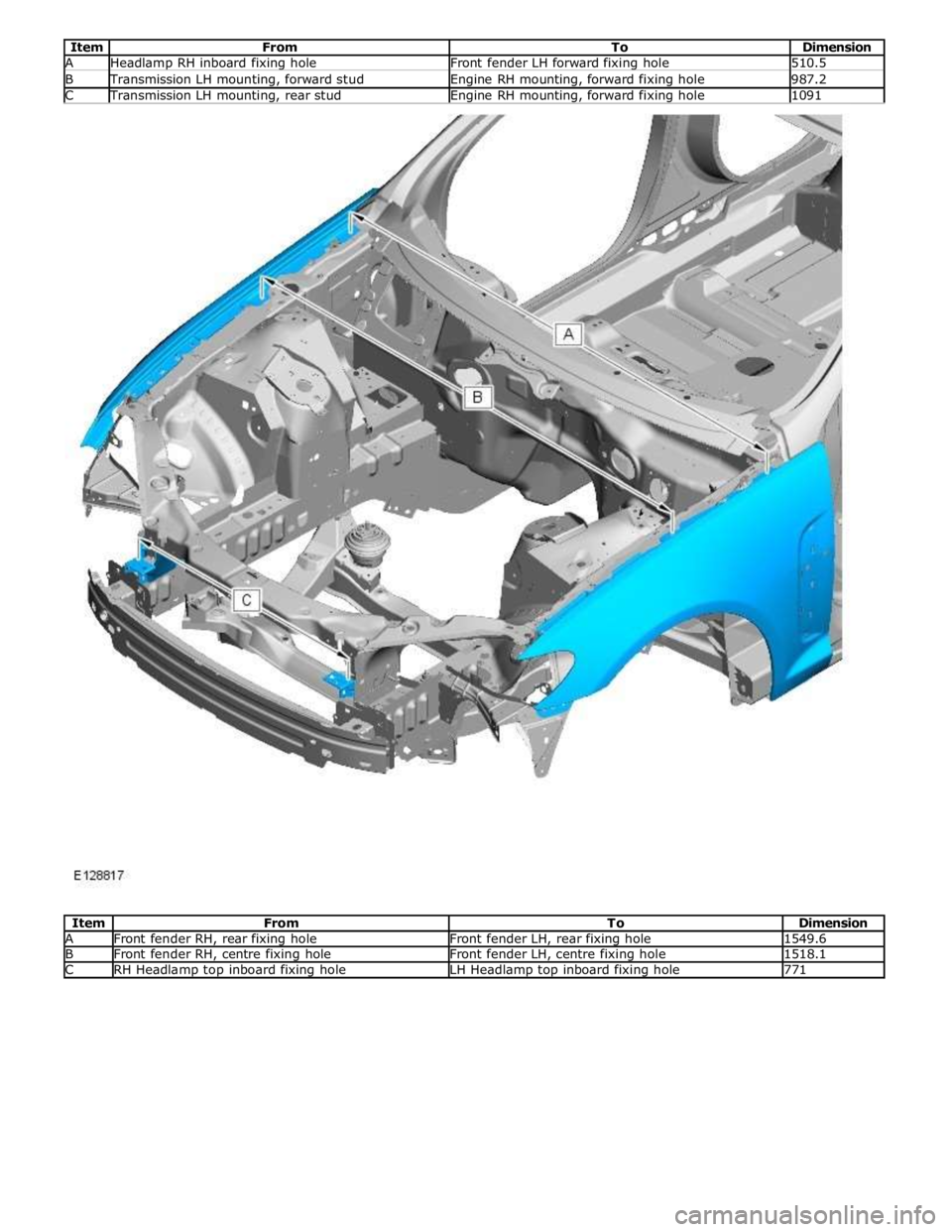
Item From To Dimension A Headlamp RH inboard fixing hole Front fender LH forward fixing hole 510.5 B Transmission LH mounting, forward stud Engine RH mounting, forward fixing hole 987.2 C Transmission LH mounting, rear stud Engine RH mounting, forward fixing hole 1091
Item From To Dimension A Front fender RH, rear fixing hole Front fender LH, rear fixing hole 1549.6 B Front fender RH, centre fixing hole Front fender LH, centre fixing hole 1518.1 C RH Headlamp top inboard fixing hole LH Headlamp top inboard fixing hole 771
Page 2784 of 3039
Front End Sheet Metal Repairs - Front Side Member
Removal and Installation
Removal Published: 11-May-2011
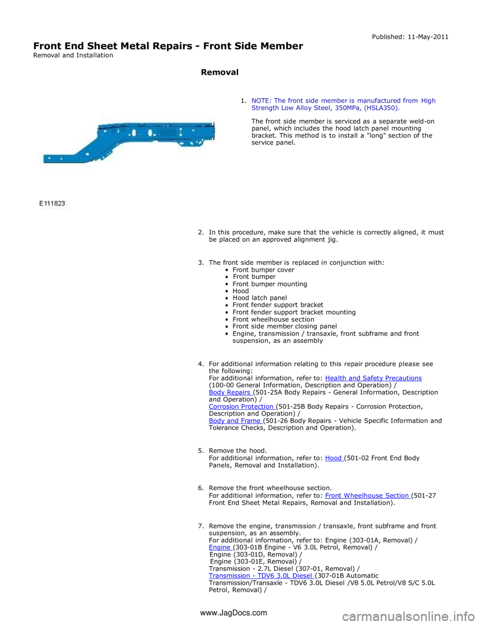
1. NOTE: The front side member is manufactured from High
Strength Low Alloy Steel, 350MPa, (HSLA350).
The front side member is serviced as a separate weld-on
panel, which includes the hood latch panel mounting
bracket. This method is to install a "long" section of the
service panel.
2. In this procedure, make sure that the vehicle is correctly aligned, it must
be placed on an approved alignment jig.
3. The front side member is replaced in conjunction with:
Front bumper cover
Front bumper
Front bumper mounting
Hood
Hood latch panel
Front fender support bracket
Front fender support bracket mounting
Front wheelhouse section
Front side member closing panel
Engine, transmission / transaxle, front subframe and front
suspension, as an assembly
4. For additional information relating to this repair procedure please see
the following:
For additional information, refer to: Health and Safety Precautions (100-00 General Information, Description and Operation) /
Body Repairs (501-25A Body Repairs - General Information, Description and Operation) /
Corrosion Protection (501-25B Body Repairs - Corrosion Protection, Description and Operation) /
Body and Frame (501-26 Body Repairs - Vehicle Specific Information and Tolerance Checks, Description and Operation).
5. Remove the hood.
For additional information, refer to: Hood (501-02 Front End Body Panels, Removal and Installation).
6. Remove the front wheelhouse section.
For additional information, refer to: Front Wheelhouse Section (501-27 Front End Sheet Metal Repairs, Removal and Installation).
7. Remove the engine, transmission / transaxle, front subframe and front
suspension, as an assembly.
For additional information, refer to: Engine (303-01A, Removal) /
Engine (303-01B Engine - V6 3.0L Petrol, Removal) / Engine (303-01D, Removal) /
Engine (303-01E, Removal) /
Transmission - 2.7L Diesel (307-01, Removal) /
Transmission - TDV6 3.0L Diesel (307-01B Automatic Transmission/Transaxle - TDV6 3.0L Diesel /V8 5.0L Petrol/V8 S/C 5.0L
Petrol, Removal) / www.JagDocs.com
Page 2785 of 3039
Transmission (307-01A Automatic Transmission/Transaxle - V6 3.0L Petrol, Removal) /
Transmission - 4.2L (307-01, Removal) /
Transmission - V8 5.0L Petrol/V8 S/C 5.0L Petrol (307-01B Automatic Transmission/Transaxle - TDV6 3.0L Diesel /V8 5.0L Petrol/V8 S/C 5.0L
Petrol, Removal) /
Front Shock Absorber (204-01 Front Suspension, Removal and Installation) /
Front Subframe - 2.7L Diesel (502-00, Removal and Installation) /
Front Subframe - V6 3.0L Petrol (502-00 Uni-Body, Subframe and Mounting System, Removal and Installation) /
Front Subframe - 4.2L, Vehicles Without: Supercharger (502-00, Removal
and Installation) /
Front Subframe - 4.2L, Vehicles With: Supercharger (502-00, Removal
and Installation).
8. Remove the pedestrian protection hood actuator.
For additional information, refer to: Pedestrian Protection Hood Actuator LH (501-20C Pedestrian Protection System, Removal and Installation) / Pedestrian Protection Hood Actuator RH (501-20C Pedestrian Protection System, Removal and Installation).
9. If the drivers side front side member and suspension top mount is to be
repaired, remove the brake master cylinder and reservoir.
For additional information, refer to: Brake Master Cylinder (206-06 Hydraulic Brake Actuation, Removal and Installation) /
Brake Fluid Reservoir (206-06 Hydraulic Brake Actuation, Removal and Installation).
10. If the left-hand front side member and suspension top mount assembly
is to be repaired, remove the fuel supply and return lines.
11. Release and position the front side member wiring harness to one side.
12. Remove any remaining miscellaneous components from the repair area.
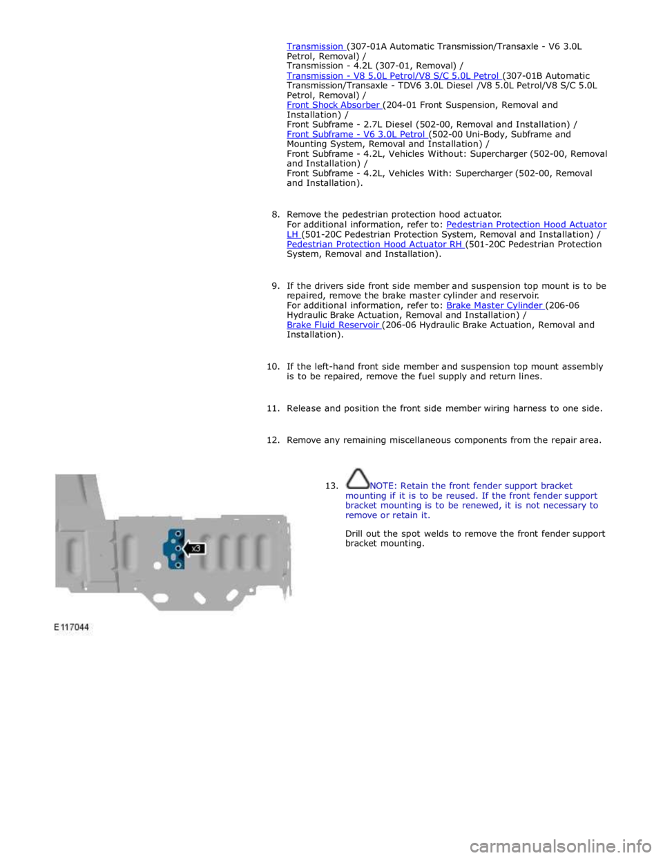
13. NOTE: Retain the front fender support bracket
mounting if it is to be reused. If the front fender support
bracket mounting is to be renewed, it is not necessary to
remove or retain it.
Drill out the spot welds to remove the front fender support
bracket mounting.
Page 2797 of 3039
(100-00 General Information, Description and Operation) /
Body Repairs (501-25A Body Repairs - General Information, Description and Operation) /
Corrosion Protection (501-25B Body Repairs - Corrosion Protection, Description and Operation) /
Body and Frame (501-26 Body Repairs - Vehicle Specific Information and Tolerance Checks, Description and Operation).
5. Remove the fender apron panel front extension.
For additional information, refer to: Fender Apron Panel Front Extension (501-27 Front End Sheet Metal Repairs, Removal and Installation).
6. Remove the front fender support bracket.
For additional information, refer to: Front Fender Support Bracket (501-27 Front End Sheet Metal Repairs, Removal and Installation).
7. Remove the fender apron panel.
For additional information, refer to: Fender Apron Panel (501-27 Front End Sheet Metal Repairs, Removal and Installation).
8. Remove the engine, transmission / transaxle, front subframe and front
suspension, as an assembly.
For additional information, refer to: Engine (303-01A, Removal) /
Engine (303-01B Engine - V6 3.0L Petrol, Removal) / Engine (303-01D, Removal) /
Engine (303-01E, Removal) /
Transmission - 2.7L Diesel (307-01, Removal) /
Transmission - TDV6 3.0L Diesel (307-01B Automatic Transmission/Transaxle - TDV6 3.0L Diesel /V8 5.0L Petrol/V8 S/C 5.0L
Petrol, Removal) /
Transmission (307-01A Automatic Transmission/Transaxle - V6 3.0L Petrol, Removal) /
Transmission - 4.2L (307-01, Removal) /
Transmission - V8 5.0L Petrol/V8 S/C 5.0L Petrol (307-01B Automatic Transmission/Transaxle - TDV6 3.0L Diesel /V8 5.0L Petrol/V8 S/C 5.0L
Petrol, Removal) /
Front Shock Absorber (204-01 Front Suspension, Removal and Installation) /
Front Subframe - 2.7L Diesel (502-00, Removal and Installation) /
Front Subframe - V6 3.0L Petrol (502-00 Uni-Body, Subframe and Mounting System, Removal and Installation) /
Front Subframe - 4.2L, Vehicles Without: Supercharger (502-00, Removal
and Installation) /
Front Subframe - 4.2L, Vehicles With: Supercharger (502-00, Removal
and Installation).
9. Remove the pedestrian protection hood actuator.
For additional information, refer to: Pedestrian Protection Hood Actuator LH (501-20C Pedestrian Protection System, Removal and Installation) / Pedestrian Protection Hood Actuator RH (501-20C Pedestrian Protection System, Removal and Installation).
10. If the drivers side front side member and suspension top mount is to be
repaired, remove the brake master cylinder and reservoir.
For additional information, refer to: Brake Master Cylinder (206-06 Hydraulic Brake Actuation, Removal and Installation) /
Brake Fluid Reservoir (206-06 Hydraulic Brake Actuation, Removal and Installation).
11. If the drivers side front side member and suspension top mount is to be
repaired, remove the brake booster.
Page 2807 of 3039
Published: 11-May-2011
Front End Sheet Metal Repairs - Front Side Member Closing Panel
Removal and Installation
Removal
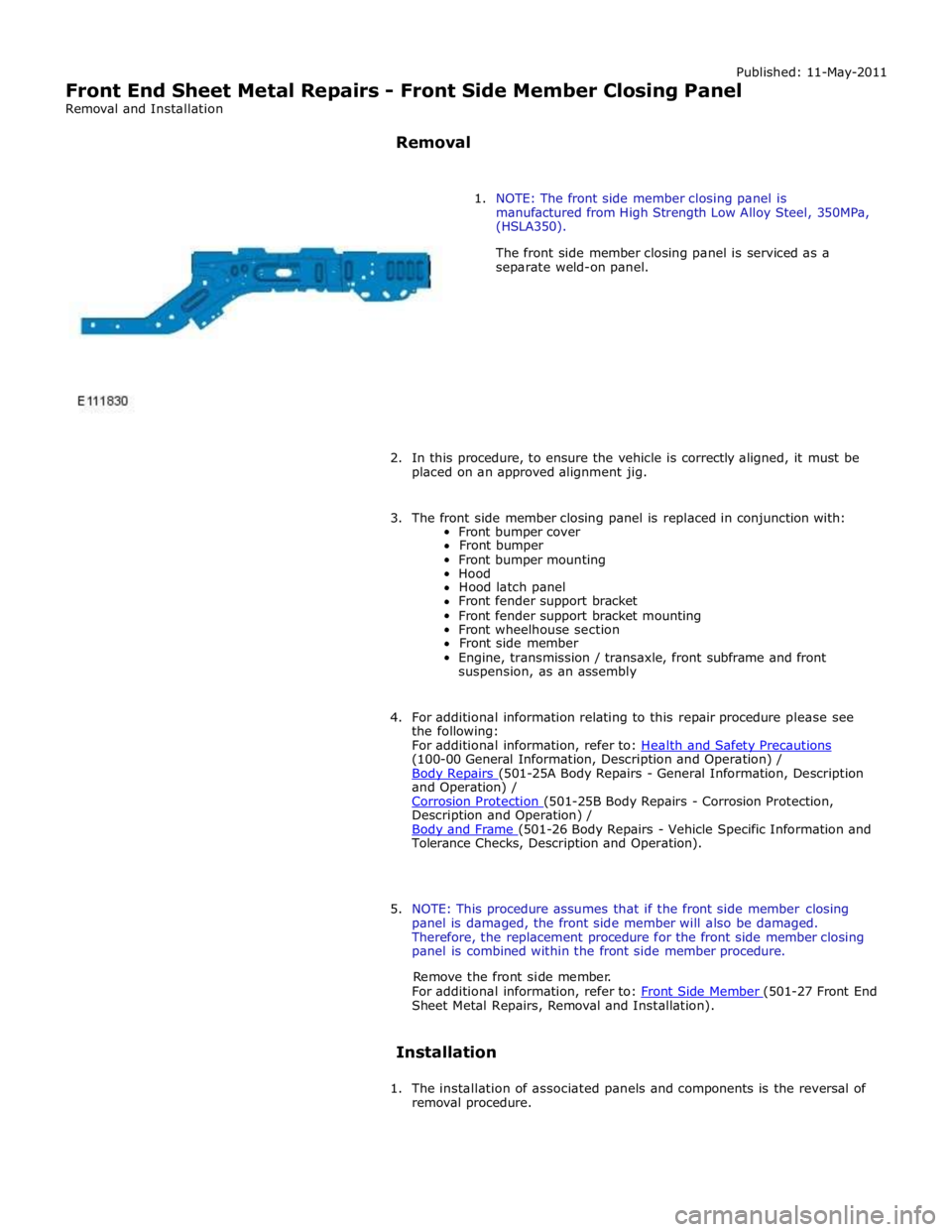
1. NOTE: The front side member closing panel is
manufactured from High Strength Low Alloy Steel, 350MPa,
(HSLA350).
The front side member closing panel is serviced as a
separate weld-on panel.
2. In this procedure, to ensure the vehicle is correctly aligned, it must be
placed on an approved alignment jig.
3. The front side member closing panel is replaced in conjunction with:
Front bumper cover
Front bumper
Front bumper mounting
Hood
Hood latch panel
Front fender support bracket
Front fender support bracket mounting
Front wheelhouse section
Front side member
Engine, transmission / transaxle, front subframe and front
suspension, as an assembly
4. For additional information relating to this repair procedure please see
the following:
For additional information, refer to: Health and Safety Precautions (100-00 General Information, Description and Operation) /
Body Repairs (501-25A Body Repairs - General Information, Description and Operation) /
Corrosion Protection (501-25B Body Repairs - Corrosion Protection, Description and Operation) /
Body and Frame (501-26 Body Repairs - Vehicle Specific Information and Tolerance Checks, Description and Operation).
5. NOTE: This procedure assumes that if the front side member closing
panel is damaged, the front side member will also be damaged.
Therefore, the replacement procedure for the front side member closing
panel is combined within the front side member procedure.
Remove the front side member.
For additional information, refer to: Front Side Member (501-27 Front End Sheet Metal Repairs, Removal and Installation).
Installation
1. The installation of associated panels and components is the reversal of
removal procedure.