2010 JAGUAR XFR Transmission
[x] Cancel search: TransmissionPage 1821 of 3039
Published: 11-May-2011
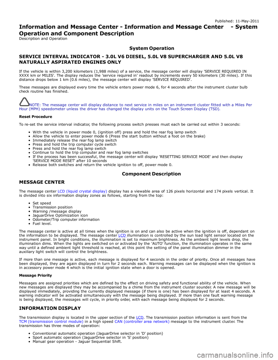
Information and Message Center - Information and Message Center - System
Operation and Component Description
Description and Operation
System Operation
SERVICE INTERVAL INDICATOR - 3.0L V6 DIESEL, 5.0L V8 SUPERCHARGER AND 5.0L V8 NATURALLY ASPIRATED ENGINES ONLY
If the vehicle is within 3,200 kilometers (1,988 miles) of a service, the message center will display 'SERVICE REQUIRED IN
XXXX km or MILES'. The display reduces the 'service required in' readout by increments every 50 kilometers (30 miles). If this
distance drops below 1 km (0.6 miles), the message center will display 'SERVICE REQUIRED'.
These messages are displayed every time the vehicle enters power mode 6, for 4 seconds after the instrument cluster bulb
check routine has finished.
NOTE: The message center will display distance to next service in miles on an instrument cluster fitted with a Miles Per
Hour (MPH) speedometer unless the driver has changed the display units on the Touch Screen Display (TSD).
Reset Procedure
To re-set the service interval indicator, the following process switch presses must each be carried out within 3 seconds:
With the vehicle in power mode 0, (ignition off) press and hold the rear fog lamp switch
Allow the vehicle to enter power mode 6 (Press the start button without a foot on the brake)
Immediately release the rear fog lamp switch
Press and hold the trip computer cycle switch
Press and hold the rear fog lamp switch
Continue to hold the trip computer and rear fog lamp switches
If the process has been successful, the message center will display 'RESETTING SERVICE MODE' and then display
'SERVICE MODE RESET' after 10 seconds
Release both switches and return the vehicle ignition to off, power mode 0.
MESSAGE CENTER Component Description
The message center LCD (liquid crystal display) display has a viewable area of 126 pixels horizontal and 174 pixels vertical. It
is divided into six information display zones as follows, starting from the top:
Set speed
Transmission position
Warning /message display
JaguarDrive Optimization icon
Odometer/Trip computer information
Fuel level.
The message center is active at all times when the ignition is on and can also be active when the ignition is off, dependant on
the information to be displayed. The message center LCD illumination is controlled by the sun load light sensor located on the instrument panel. In bright conditions, the illumination is set to maximum brightness. As the ambient light levels drop, the
illumination dims. When the lights are switched on or activated by the 'AUTO' function, the illumination operates in the same
way until a defined ambient light threshold is reached, at this point the setting of the panel illumination dimmer in the
auxiliary light switch will control the brightness.
If more than one message is active, each message is displayed for 4 seconds in the order of priority. Once all messages have
been displayed, they are again displayed in turn for 2 seconds each. Warning messages can be displayed when the ignition is
in accessory power mode 4 which is the initial ignition state when a door is opened.
Message Priority
Messages are assigned priorities which are defined by the effect on driving safety and functional ability of the vehicle. When
new messages are displayed they may be accompanied by a chime from the instrument cluster sounder. A new message will be
displayed immediately, providing the currently displayed message (if there is one) has been displayed for at least 4 seconds. A
warning indicator will be activated simultaneously with the message being displayed. If more than one fault warning message
is being displayed, the messages will cycle, in priority order, with each message being displayed for 2 seconds.
INFORMATION DISPLAY
The transmission display is located in the upper section of the LCD. The transmission position information is sent from the TCM (transmission control module) in a high speed CAN (controller area network) message to the instrument cluster. The
transmission has three modes of operation:
Conventional automatic operation (JaguarDrive selector in 'D' position)
Sport automatic operation (JaguarDrive selector in 'S' position)
Manual gear operation - Jaguar Sequential Shift.
Page 1822 of 3039
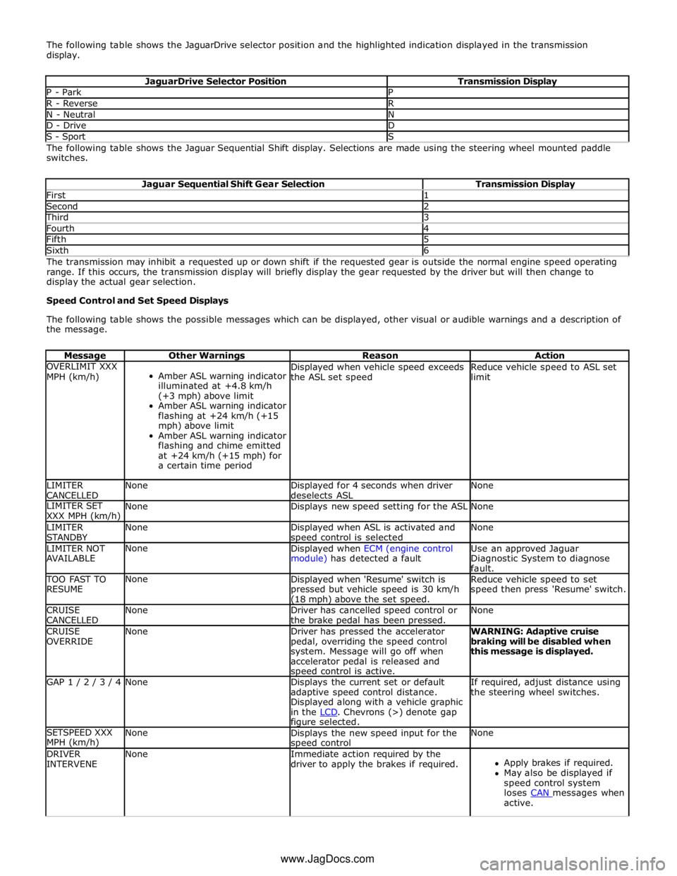
The following table shows the JaguarDrive selector position and the highlighted indication displayed in the transmission
display.
JaguarDrive Selector Position Transmission Display P - Park P R - Reverse R N - Neutral N D - Drive D S - Sport S The following table shows the Jaguar Sequential Shift display. Selections are made using the steering wheel mounted paddle
switches.
Jaguar Sequential Shift Gear Selection Transmission Display First 1 Second 2 Third 3 Fourth 4 Fifth 5 Sixth 6 The transmission may inhibit a requested up or down shift if the requested gear is outside the normal engine speed operating
range. If this occurs, the transmission display will briefly display the gear requested by the driver but will then change to
display the actual gear selection.
Speed Control and Set Speed Displays
The following table shows the possible messages which can be displayed, other visual or audible warnings and a description of
the message.
Message Other Warnings Reason Action OVERLIMIT XXX
MPH (km/h)
Amber ASL warning indicator
illuminated at +4.8 km/h
(+3 mph) above limit
Amber ASL warning indicator
flashing at +24 km/h (+15
mph) above limit
Amber ASL warning indicator
flashing and chime emitted
at +24 km/h (+15 mph) for
a certain time period Displayed when vehicle speed exceeds
the ASL set speed Reduce vehicle speed to ASL set
limit LIMITER
CANCELLED None
Displayed for 4 seconds when driver
deselects ASL None LIMITER SET
XXX MPH (km/h) None Displays new speed setting for the ASL None LIMITER
STANDBY None
Displayed when ASL is activated and speed control is selected None LIMITER NOT
AVAILABLE None
Displayed when ECM (engine control
module) has detected a fault Use an approved Jaguar
Diagnostic System to diagnose
fault. TOO FAST TO
RESUME None
Displayed when 'Resume' switch is
pressed but vehicle speed is 30 km/h (18 mph) above the set speed. Reduce vehicle speed to set
speed then press 'Resume' switch. CRUISE
CANCELLED None
Driver has cancelled speed control or
the brake pedal has been pressed. None CRUISE
OVERRIDE None
Driver has pressed the accelerator
pedal, overriding the speed control
system. Message will go off when
accelerator pedal is released and speed control is active. WARNING: Adaptive cruise
braking will be disabled when
this message is displayed. GAP 1 / 2 / 3 / 4 None
Displays the current set or default
adaptive speed control distance.
Displayed along with a vehicle graphic
in the LCD. Chevrons (>) denote gap figure selected. If required, adjust distance using
the steering wheel switches. SETSPEED XXX
MPH (km/h) None
Displays the new speed input for the speed control None DRIVER
INTERVENE None
Immediate action required by the
driver to apply the brakes if required.
Apply brakes if required.
May also be displayed if
speed control system
loses CAN messages when active. www.JagDocs.com
Page 1825 of 3039
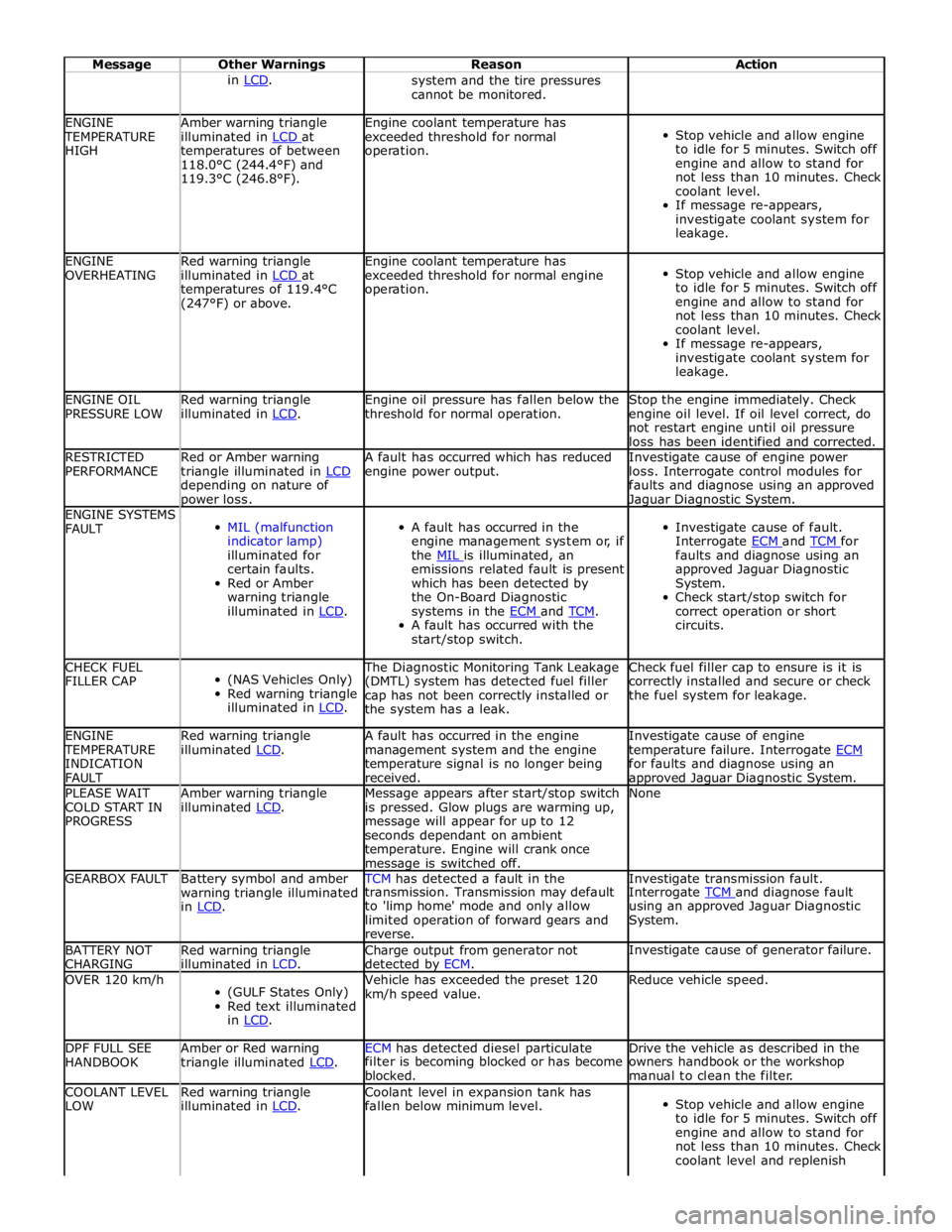
Message Other Warnings Reason Action in LCD. system and the tire pressures
cannot be monitored. ENGINE TEMPERATURE
HIGH Amber warning triangle
illuminated in LCD at temperatures of between
118.0°C (244.4°F) and
119.3°C (246.8°F). Engine coolant temperature has
exceeded threshold for normal
operation.
Stop vehicle and allow engine
to idle for 5 minutes. Switch off
engine and allow to stand for
not less than 10 minutes. Check
coolant level.
If message re-appears,
investigate coolant system for
leakage. ENGINE
OVERHEATING Red warning triangle
illuminated in LCD at temperatures of 119.4°C
(247°F) or above. Engine coolant temperature has
exceeded threshold for normal engine
operation.
Stop vehicle and allow engine
to idle for 5 minutes. Switch off
engine and allow to stand for
not less than 10 minutes. Check
coolant level.
If message re-appears,
investigate coolant system for
leakage. ENGINE OIL
PRESSURE LOW Red warning triangle
illuminated in LCD. Engine oil pressure has fallen below the
threshold for normal operation. Stop the engine immediately. Check
engine oil level. If oil level correct, do
not restart engine until oil pressure
loss has been identified and corrected. RESTRICTED
PERFORMANCE Red or Amber warning
triangle illuminated in LCD depending on nature of power loss. A fault has occurred which has reduced
engine power output. Investigate cause of engine power
loss. Interrogate control modules for
faults and diagnose using an approved Jaguar Diagnostic System. ENGINE SYSTEMS
FAULT
MIL (malfunction
indicator lamp)
illuminated for
certain faults.
Red or Amber
warning triangle
illuminated in LCD.
A fault has occurred in the
engine management system or, if
the MIL is illuminated, an emissions related fault is present
which has been detected by
the On-Board Diagnostic
systems in the ECM and TCM. A fault has occurred with the
start/stop switch.
Investigate cause of fault.
Interrogate ECM and TCM for faults and diagnose using an
approved Jaguar Diagnostic
System.
Check start/stop switch for
correct operation or short
circuits. CHECK FUEL
FILLER CAP
(NAS Vehicles Only)
Red warning triangle
illuminated in LCD. The Diagnostic Monitoring Tank Leakage
(DMTL) system has detected fuel filler
cap has not been correctly installed or
the system has a leak. Check fuel filler cap to ensure is it is
correctly installed and secure or check
the fuel system for leakage. ENGINE TEMPERATURE
INDICATION
FAULT Red warning triangle
illuminated LCD. A fault has occurred in the engine
management system and the engine
temperature signal is no longer being
received. Investigate cause of engine
temperature failure. Interrogate ECM for faults and diagnose using an approved Jaguar Diagnostic System. PLEASE WAIT
COLD START IN
PROGRESS Amber warning triangle
illuminated LCD. Message appears after start/stop switch
is pressed. Glow plugs are warming up,
message will appear for up to 12
seconds dependant on ambient
temperature. Engine will crank once message is switched off. None GEARBOX FAULT
Battery symbol and amber
warning triangle illuminated
in LCD. TCM has detected a fault in the Investigate transmission fault. transmission. Transmission may default
to 'limp home' mode and only allow
limited operation of forward gears and
reverse. Interrogate TCM and diagnose fault using an approved Jaguar Diagnostic
System. BATTERY NOT
CHARGING Red warning triangle
illuminated in LCD. Charge output from generator not
detected by ECM. Investigate cause of generator failure. OVER 120 km/h
(GULF States Only)
Red text illuminated
in LCD. Vehicle has exceeded the preset 120
km/h speed value. Reduce vehicle speed. DPF FULL SEE
HANDBOOK Amber or Red warning
triangle illuminated LCD. ECM has detected diesel particulate Drive the vehicle as described in the filter is becoming blocked or has become
blocked. owners handbook or the workshop
manual to clean the filter. COOLANT LEVEL
LOW Red warning triangle
illuminated in LCD. Coolant level in expansion tank has
fallen below minimum level.
Stop vehicle and allow engine
to idle for 5 minutes. Switch off
engine and allow to stand for
not less than 10 minutes. Check
coolant level and replenish
Page 1827 of 3039
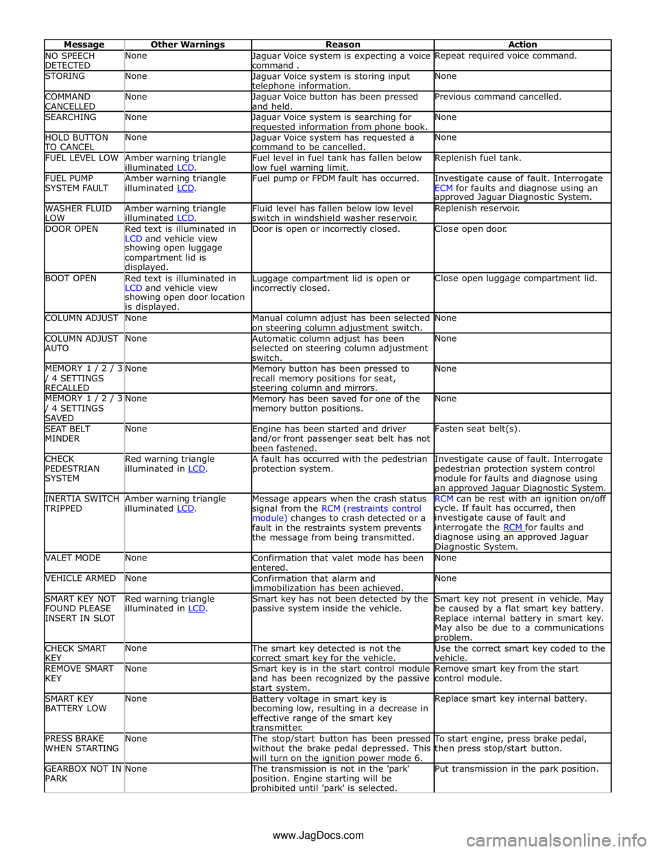
NO SPEECH
DETECTED None
Jaguar Voice system is expecting a voice
command . Repeat required voice command. STORING None
Jaguar Voice system is storing input telephone information. None COMMAND
CANCELLED None
Jaguar Voice button has been pressed
and held. Previous command cancelled. SEARCHING None
Jaguar Voice system is searching for requested information from phone book. None HOLD BUTTON TO CANCEL None
Jaguar Voice system has requested a
command to be cancelled. None FUEL LEVEL LOW
Amber warning triangle
illuminated LCD. Fuel level in fuel tank has fallen below
low fuel warning limit. Replenish fuel tank. FUEL PUMP
SYSTEM FAULT Amber warning triangle
illuminated LCD. Fuel pump or FPDM fault has occurred.
Investigate cause of fault. Interrogate
ECM for faults and diagnose using an approved Jaguar Diagnostic System. WASHER FLUID
LOW Amber warning triangle
illuminated LCD. Fluid level has fallen below low level
switch in windshield washer reservoir. Replenish reservoir. DOOR OPEN
Red text is illuminated in
LCD and vehicle view Door is open or incorrectly closed. Close open door. showing open luggage
compartment lid is
displayed. BOOT OPEN
Red text is illuminated in
LCD and vehicle view Luggage compartment lid is open or incorrectly closed. Close open luggage compartment lid. showing open door location
is displayed. COLUMN ADJUST None
Manual column adjust has been selected
on steering column adjustment switch. None COLUMN ADJUST
AUTO None
Automatic column adjust has been
selected on steering column adjustment
switch. None MEMORY 1 / 2 / 3 / 4 SETTINGS
RECALLED None
Memory button has been pressed to
recall memory positions for seat, steering column and mirrors. None MEMORY 1 / 2 / 3 / 4 SETTINGS
SAVED None
Memory has been saved for one of the
memory button positions. None SEAT BELT
MINDER None
Engine has been started and driver
and/or front passenger seat belt has not
been fastened. Fasten seat belt(s). CHECK
PEDESTRIAN
SYSTEM Red warning triangle
illuminated in LCD. A fault has occurred with the pedestrian
protection system. Investigate cause of fault. Interrogate
pedestrian protection system control
module for faults and diagnose using
an approved Jaguar Diagnostic System. INERTIA SWITCH TRIPPED Amber warning triangle
illuminated LCD. Message appears when the crash status
signal from the RCM (restraints control
module) changes to crash detected or a
fault in the restraints system prevents
the message from being transmitted. RCM can be rest with an ignition on/off cycle. If fault has occurred, then
investigate cause of fault and
interrogate the RCM for faults and diagnose using an approved Jaguar
Diagnostic System. VALET MODE None
Confirmation that valet mode has been
entered. None VEHICLE ARMED None
Confirmation that alarm and
immobilization has been achieved. None SMART KEY NOT
FOUND PLEASE
INSERT IN SLOT Red warning triangle
illuminated in LCD. Smart key has not been detected by the
passive system inside the vehicle. Smart key not present in vehicle. May
be caused by a flat smart key battery.
Replace internal battery in smart key.
May also be due to a communications problem. CHECK SMART
KEY None The smart key detected is not the
correct smart key for the vehicle. Use the correct smart key coded to the
vehicle. REMOVE SMART
KEY None
Smart key is in the start control module
and has been recognized by the passive
start system. Remove smart key from the start
control module. SMART KEY
BATTERY LOW None
Battery voltage in smart key is
becoming low, resulting in a decrease in
effective range of the smart key
transmitter. Replace smart key internal battery. PRESS BRAKE
WHEN STARTING None The stop/start button has been pressed
without the brake pedal depressed. This
will turn on the ignition power mode 6. To start engine, press brake pedal,
then press stop/start button. GEARBOX NOT IN
PARK None The transmission is not in the 'park'
position. Engine starting will be prohibited until 'park' is selected. Put transmission in the park position. www.JagDocs.com
Page 1847 of 3039
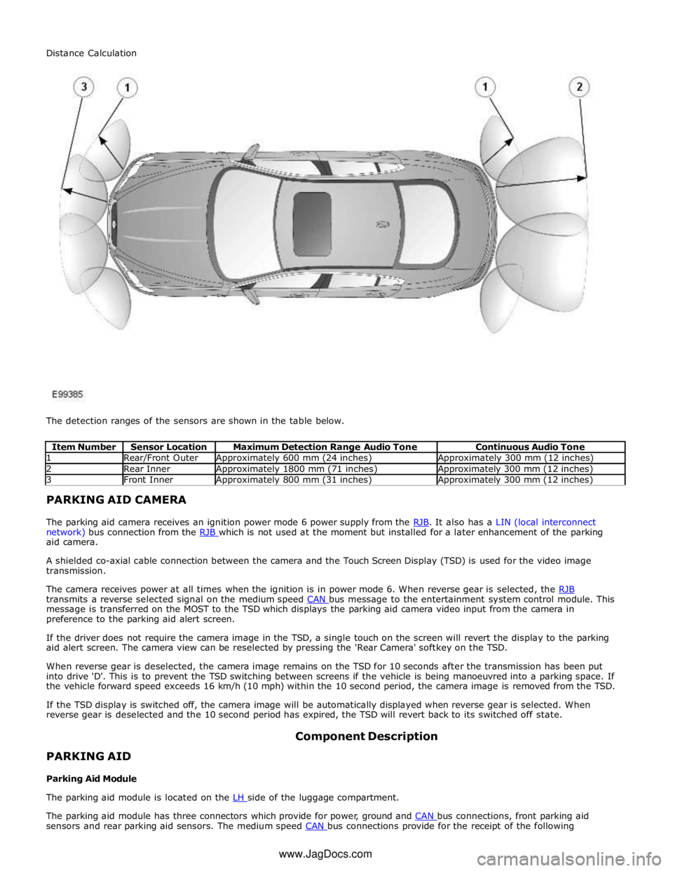
1 Rear/Front Outer Approximately 600 mm (24 inches) Approximately 300 mm (12 inches) 2 Rear Inner Approximately 1800 mm (71 inches) Approximately 300 mm (12 inches) 3 Front Inner Approximately 800 mm (31 inches) Approximately 300 mm (12 inches) PARKING AID CAMERA
The parking aid camera receives an ignition power mode 6 power supply from the RJB. It also has a LIN (local interconnect network) bus connection from the RJB which is not used at the moment but installed for a later enhancement of the parking aid camera.
A shielded co-axial cable connection between the camera and the Touch Screen Display (TSD) is used for the video image
transmission.
The camera receives power at all times when the ignition is in power mode 6. When reverse gear is selected, the RJB transmits a reverse selected signal on the medium speed CAN bus message to the entertainment system control module. This message is transferred on the MOST to the TSD which displays the parking aid camera video input from the camera in
preference to the parking aid alert screen.
If the driver does not require the camera image in the TSD, a single touch on the screen will revert the display to the parking
aid alert screen. The camera view can be reselected by pressing the 'Rear Camera' softkey on the TSD.
When reverse gear is deselected, the camera image remains on the TSD for 10 seconds after the transmission has been put
into drive 'D'. This is to prevent the TSD switching between screens if the vehicle is being manoeuvred into a parking space. If
the vehicle forward speed exceeds 16 km/h (10 mph) within the 10 second period, the camera image is removed from the TSD.
If the TSD display is switched off, the camera image will be automatically displayed when reverse gear is selected. When
reverse gear is deselected and the 10 second period has expired, the TSD will revert back to its switched off state.
PARKING AID
Parking Aid Module Component Description
The parking aid module is located on the LH side of the luggage compartment.
The parking aid module has three connectors which provide for power, ground and CAN bus connections, front parking aid sensors and rear parking aid sensors. The medium speed CAN bus connections provide for the receipt of the following Distance Calculation
www.JagDocs.com
Page 1848 of 3039
information from other systems:
ABS (anti-lock brake system) module - Road speed signal
TCM (transmission control module) - Reverse gear engaged signal
Trailer module - Trailer attached to vehicle
The module also outputs messages on the medium speed CAN bus which are received by the integrated audio module. The integrated audio module processes these messages and converts them into Media Orientated System Transport (MOST) signals
which are passed to the audio system power amplifier. These signals are then used by the power amplifier to emit the
applicable warning tones from the front or rear audio speakers when an object is detected by the front or rear parking aid
sensors. A warning tone can also be emitted to alert the driver to a fault in the parking aid system.
The control module has a diagnostic connection via the medium speed CAN bus to enable faults to be retrieved using the
Jaguar approved diagnostic equipment. Additionally an on-board diagnostic routine within the control module constantly
monitors the system and alerts the driver to a system fault by emitting a 3 second continuous tone through the rear audio
system speakers when the ignition is switched on. If front parking aid sensors are fitted, the control switch LED will also flash
6 times.
Parking Aid Sensors
Four ultrasonic sensors are located in the front (if fitted) and rear bumpers.
Each sensor has a three pin connector which mates with a bumper harness, which in turn is connected to the main body
harness. Three pins provide for power supply, ground and signal lines to and from the parking aid module.
The parking aid module controls the operation of each sensor using a digital output on the signal line. The module controls the
sensor in one of two modes; combined transmitter and receiver mode or receiver mode only.
Parking Aid Switch
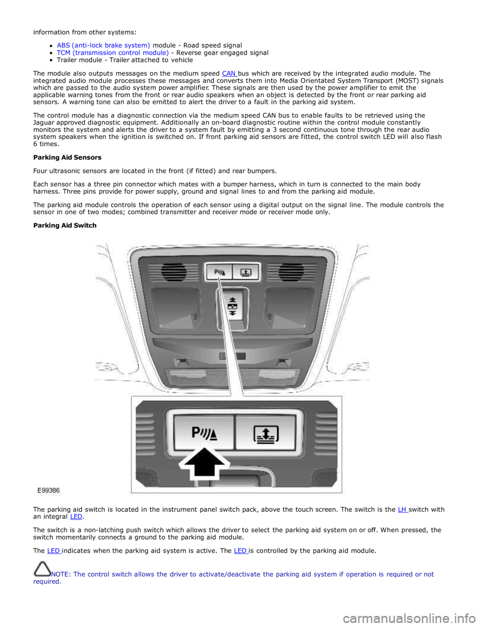
The parking aid switch is located in the instrument panel switch pack, above the touch screen. The switch is the LH switch with an integral LED.
The switch is a non-latching push switch which allows the driver to select the parking aid system on or off. When pressed, the
switch momentarily connects a ground to the parking aid module.
The LED indicates when the parking aid system is active. The LED is controlled by the parking aid module.
NOTE: The control switch allows the driver to activate/deactivate the parking aid system if operation is required or not
required.
Page 1849 of 3039
PARKING AID CAMERA
The parking aid camera receives an ignition power mode 6 power supply from the RJB. It also has a LIN bus connection with the RJB, which is used as a gateway. A shielded co-axial cable connection between the camera and the TSD is used for the video image transmission.
The camera receives power at all times when the ignition is in power mode 6. When reverse gear is selected, the RJB transmits a reverse selected message on the medium speed CAN bus. The information and entertainment module transfers the message on the MOST ring to the TSD, which displays the video input from the parking aid camera in preference to the parking
aid alert screen.
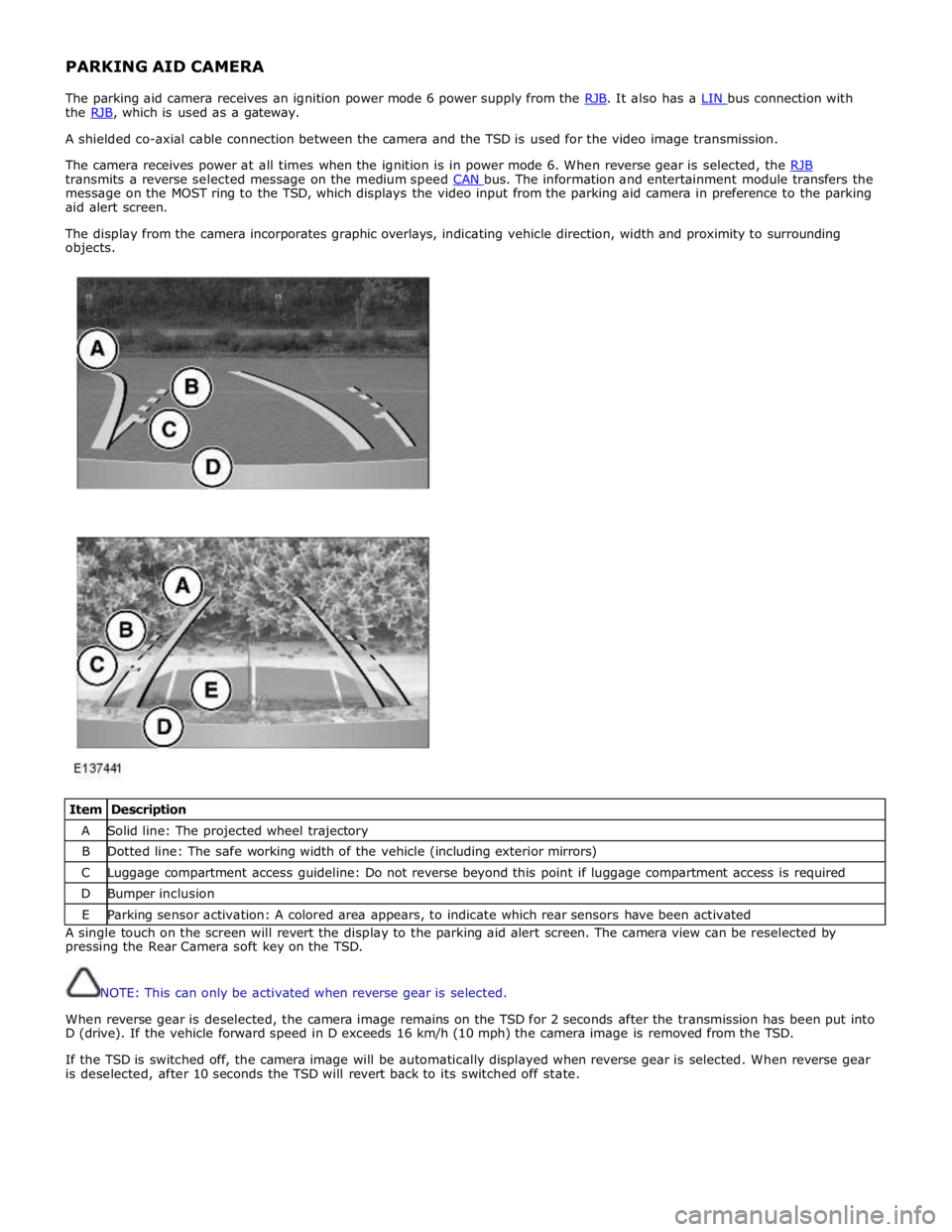
The display from the camera incorporates graphic overlays, indicating vehicle direction, width and proximity to surrounding
objects.
Item Description A Solid line: The projected wheel trajectory B Dotted line: The safe working width of the vehicle (including exterior mirrors) C Luggage compartment access guideline: Do not reverse beyond this point if luggage compartment access is required D Bumper inclusion E Parking sensor activation: A colored area appears, to indicate which rear sensors have been activated A single touch on the screen will revert the display to the parking aid alert screen. The camera view can be reselected by
pressing the Rear Camera soft key on the TSD.
NOTE: This can only be activated when reverse gear is selected.
When reverse gear is deselected, the camera image remains on the TSD for 2 seconds after the transmission has been put into
D (drive). If the vehicle forward speed in D exceeds 16 km/h (10 mph) the camera image is removed from the TSD.
If the TSD is switched off, the camera image will be automatically displayed when reverse gear is selected. When reverse gear
is deselected, after 10 seconds the TSD will revert back to its switched off state.
Page 1881 of 3039
6 Instrument Cluster 7 Rear Junction Box (RJB) CONTROL DIAGRAM - DUAL BATTERY SYSTEM VEHICLES
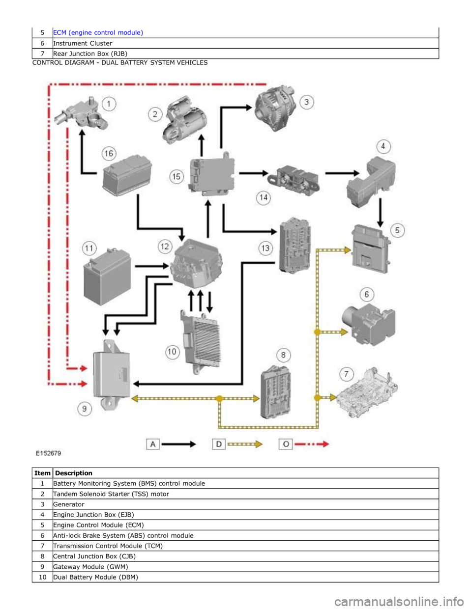
Item Description 1 Battery Monitoring System (BMS) control module 2 Tandem Solenoid Starter (TSS) motor 3 Generator 4 Engine Junction Box (EJB) 5 Engine Control Module (ECM) 6 Anti-lock Brake System (ABS) control module 7 Transmission Control Module (TCM) 8 Central Junction Box (CJB) 9 Gateway Module (GWM) 10 Dual Battery Module (DBM)