2010 JAGUAR XFR Transmission
[x] Cancel search: TransmissionPage 1539 of 3039
Published: 11-May-2011
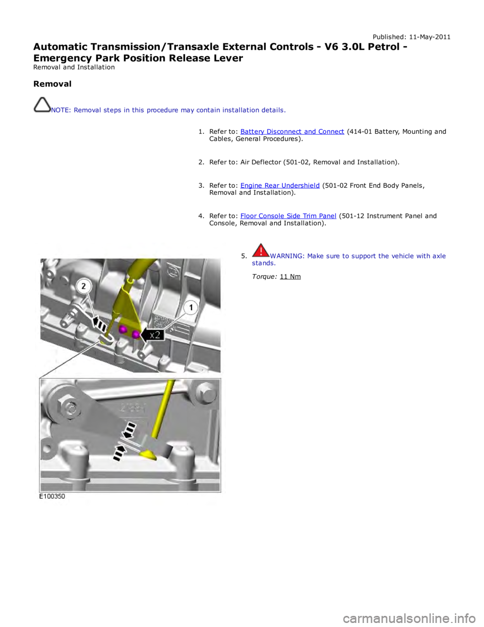
Automatic Transmission/Transaxle External Controls - V6 3.0L Petrol -
Emergency Park Position Release Lever
Removal and Installation
Removal
NOTE: Removal steps in this procedure may contain inst allation details.
Refer to: Batt ery Disconnect and Connect (414-01 Battery, Mounting and
Cables, General Procedures). 1.
Refer to: Air Deflector (501-02, Removal and Installation). 2.
Refer to: Engine Rear Undershield (501-02 Front End Body Panels,
Removal and Installation). 3.
Refer to: Floor Console Side Trim Panel (501-12 Inst rument Panel and
Console, Removal and Installation). 4.WARNING: Make sure to support the vehicle with axle
stands.
T orque: 11 Nm 5.
Page 1542 of 3039
Published: 11-May-2011
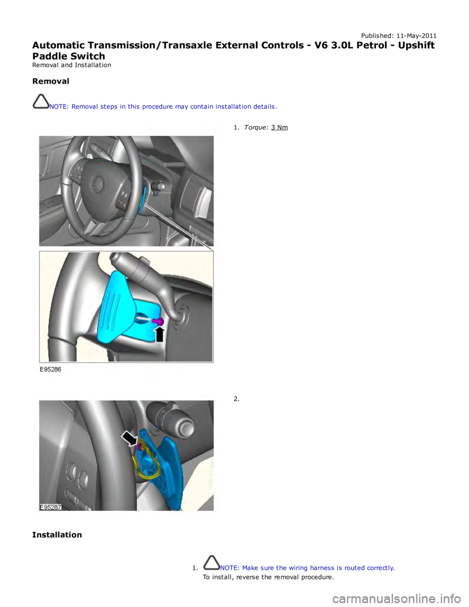
Automatic Transmission/Transaxle External Controls - V6 3.0L Petrol - Upshift
Paddle Switch
Removal and Installation
Removal
NOTE: Removal steps in this procedure may contain inst allation details.T orque: 3 Nm 1.2.
Installation
NOTE: Make sure the wiring harness is routed correct ly. 1.To inst all, reverse t he removal procedure.
Page 1543 of 3039
Published: 11-May-2011
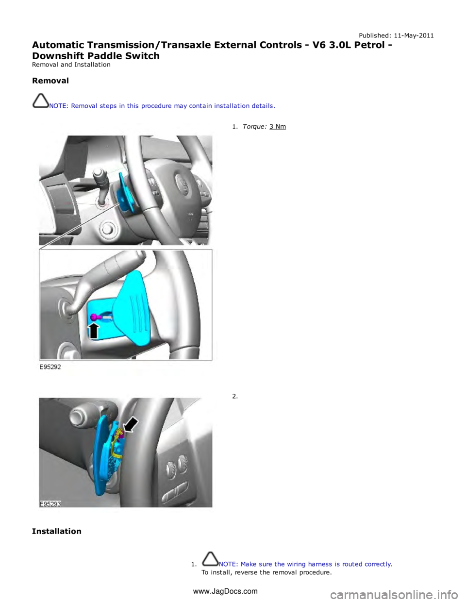
Automatic Transmission/Transaxle External Controls - V6 3.0L Petrol -
Downshift Paddle Switch
Removal and Installation
Removal
NOTE: Removal steps in this procedure may contain inst allation details.T orque: 3 Nm 1.2.
Installation
NOTE: Make sure the wiring harness is routed correct ly. 1.To inst all, reverse t he removal procedure.
www.JagDocs.com
Page 1597 of 3039
Symptom Possible Causes Action Electronic engine control
Throttle motor
Restricted accelerator pedal
travel (carpet, etc)
Ignition system
Transmission malfunction Check for air leakage in air intake system
Ensure accelerator pedal is free from restriction
Check for electronic engine controls, ignition, engine
emission system and transmission related DTCs and
refer to the relevant DTC Index Engine backfires
Fuel pump/lines
Air leakage
Electronic engine controls
Ignition system
Sticking variable camshaft
timing (VCT) hub
Check for fuel system failures
Check for air leakage in intake air system
Check for electronic engine controls, ignition system
and VCT system related DTCs and refer to the
relevant DTC Index Engine surges
Fuel pump/lines
Electronic engine controls
Throttle motor
Ignition system
Check for fuel system failures
Check for electronic engine controls, throttle system
and ignition system related DTCs and refer to the
relevant DTC Index Engine detonates/knocks
Fuel pump/lines
Air leakage
Electronic engine controls
Sticking VCT hub
Check for fuel system failures
Check for air leakage in intake air system
Check for electronic engine controls and VCT system
related DTCs and refer to the relevant DTC Index No throttle response
Electronic engine controls
Throttle motor
Check for electronic engine controls and throttle
system related DTCs and refer to the relevant DTC
Index Poor throttle response
Breather system
disconnected/restricted
Electronic engine controls
Transmission malfunction
Traction control event
Air leakage
Ensure the engine breather system is free from
restriction and is correctly installed
Check for electronic engine controls, transmission
and traction control related DTCs and refer to the
related DTC Index
Check for air leakage in intake air system Fuel gauge reading empty
with fuel in the fuel tank
Active fuel level sensor
circuit open circuit
Passive fuel level sensor
circuit open circuit
Instrument cluster internal
failure
Using the manufacturer approved diagnostic system,
perform the guided diagnostic routine - Fuel Level
Sensor Test Fuel gauge not reading empty
with no fuel in the fuel tank
Jet pump fault
Fuel crossover tube blocked
or leaking
Using the manufacturer approved diagnostic system,
check datalogger signals - Fuel Sender 2 (0x61B8) -
Fuel Sender 1 (0x61B7). Refer to the table below. If
the right sensor reads empty when the left sensor
reads more than empty, check that the jet pump is
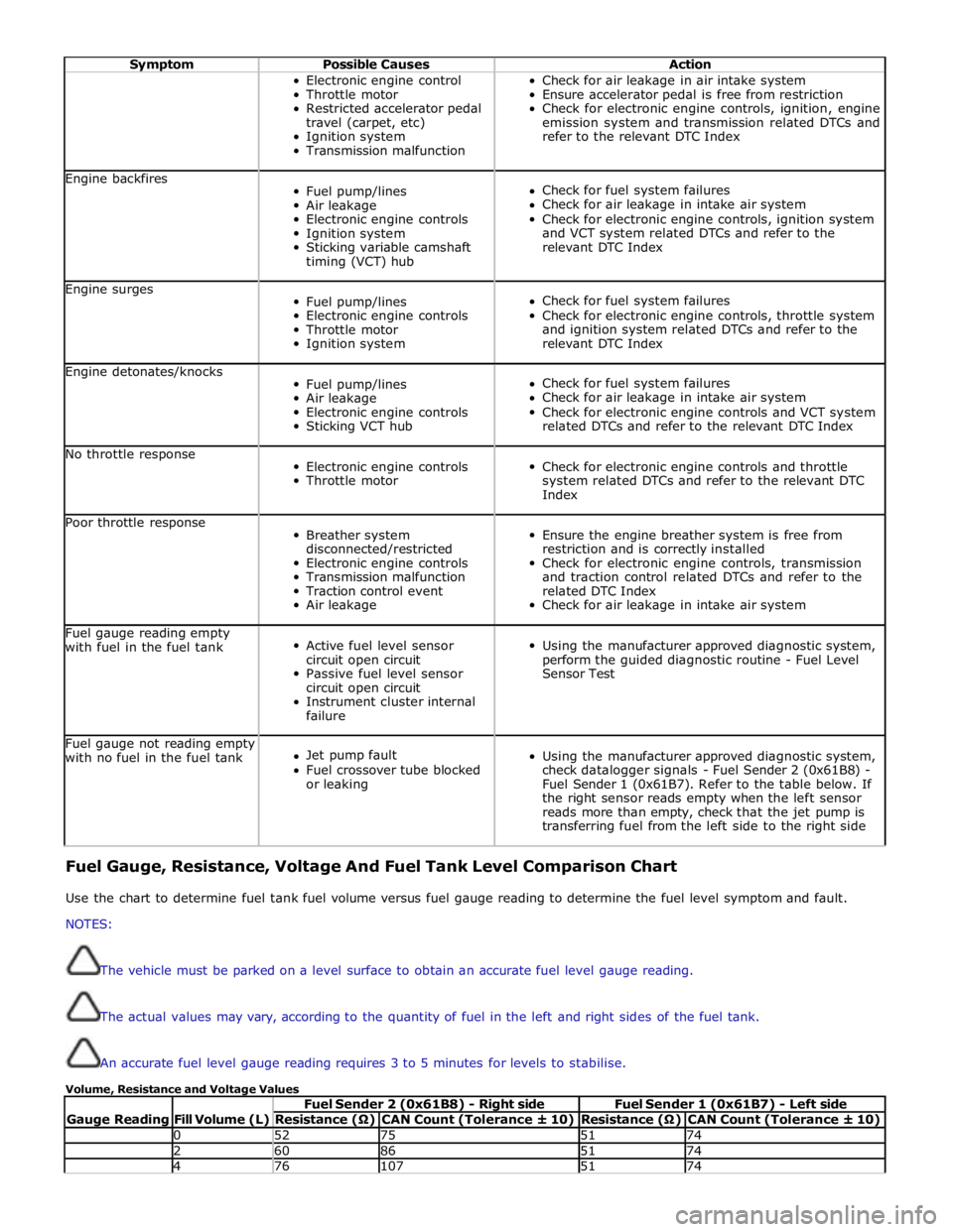
transferring fuel from the left side to the right side Fuel Gauge, Resistance, Voltage And Fuel Tank Level Comparison Chart
Use the chart to determine fuel tank fuel volume versus fuel gauge reading to determine the fuel level symptom and fault.
NOTES:
The vehicle must be parked on a level surface to obtain an accurate fuel level gauge reading.
The actual values may vary, according to the quantity of fuel in the left and right sides of the fuel tank.
An accurate fuel level gauge reading requires 3 to 5 minutes for levels to stabilise.
Volume, Resistance and Voltage Values
Gauge Reading
Fill Volume (L) Fuel Sender 2 (0x61B8) - Right side Fuel Sender 1 (0x61B7) - Left side Resistance (Ω) CAN Count (Tolerance ± 10) Resistance (Ω) CAN Count (Tolerance ± 10) 0 52 75 51 74 2 60 86 51 74 4 76 107 51 74
Page 1607 of 3039
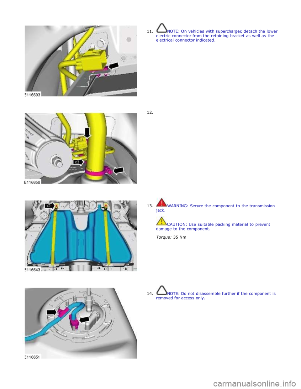
11.
12. NOTE: On vehicles with supercharger, detach the lower
electric connector from the retaining bracket as well as the
electrical connector indicated.
13.
jack.
WARNING: Secure the component to the transmission
CAUTION: Use suitable packing material to prevent
damage to the component.
Torque: 35 Nm
14. NOTE: Do not disassemble further if the component is
removed for access only.
Page 1641 of 3039
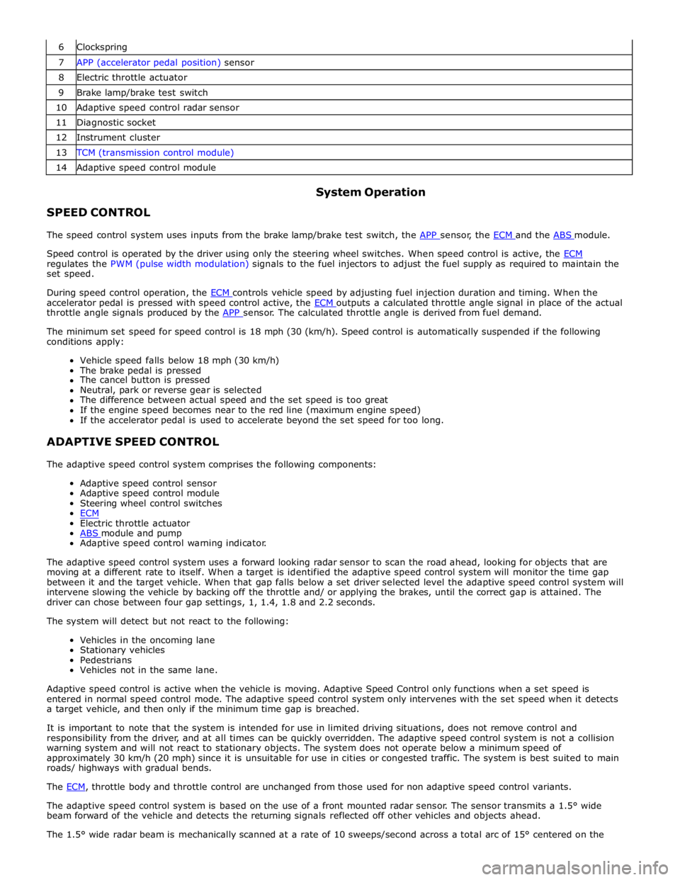
6 Clockspring 7 APP (accelerator pedal position) sensor 8 Electric throttle actuator 9 Brake lamp/brake test switch 10 Adaptive speed control radar sensor 11 Diagnostic socket 12 Instrument cluster 13 TCM (transmission control module) 14 Adaptive speed control module
SPEED CONTROL System Operation
The speed control system uses inputs from the brake lamp/brake test switch, the APP sensor, the ECM and the ABS module.
Speed control is operated by the driver using only the steering wheel switches. When speed control is active, the ECM regulates the PWM (pulse width modulation) signals to the fuel injectors to adjust the fuel supply as required to maintain the
set speed.
During speed control operation, the ECM controls vehicle speed by adjusting fuel injection duration and timing. When the accelerator pedal is pressed with speed control active, the ECM outputs a calculated throttle angle signal in place of the actual throttle angle signals produced by the APP sensor. The calculated throttle angle is derived from fuel demand.
The minimum set speed for speed control is 18 mph (30 (km/h). Speed control is automatically suspended if the following
conditions apply:
Vehicle speed falls below 18 mph (30 km/h)
The brake pedal is pressed
The cancel button is pressed
Neutral, park or reverse gear is selected
The difference between actual speed and the set speed is too great
If the engine speed becomes near to the red line (maximum engine speed)
If the accelerator pedal is used to accelerate beyond the set speed for too long.
ADAPTIVE SPEED CONTROL
The adaptive speed control system comprises the following components:
Adaptive speed control sensor
Adaptive speed control module
Steering wheel control switches
ECM
Electric throttle actuator
ABS module and pump Adaptive speed control warning indicator.
The adaptive speed control system uses a forward looking radar sensor to scan the road ahead, looking for objects that are
moving at a different rate to itself. When a target is identified the adaptive speed control system will monitor the time gap
between it and the target vehicle. When that gap falls below a set driver selected level the adaptive speed control system will
intervene slowing the vehicle by backing off the throttle and/ or applying the brakes, until the correct gap is attained. The
driver can chose between four gap settings, 1, 1.4, 1.8 and 2.2 seconds.
The system will detect but not react to the following:
Vehicles in the oncoming lane
Stationary vehicles
Pedestrians
Vehicles not in the same lane.
Adaptive speed control is active when the vehicle is moving. Adaptive Speed Control only functions when a set speed is
entered in normal speed control mode. The adaptive speed control system only intervenes with the set speed when it detects
a target vehicle, and then only if the minimum time gap is breached.
It is important to note that the system is intended for use in limited driving situations, does not remove control and
responsibility from the driver, and at all times can be quickly overridden. The adaptive speed control system is not a collision
warning system and will not react to stationary objects. The system does not operate below a minimum speed of
approximately 30 km/h (20 mph) since it is unsuitable for use in cities or congested traffic. The system is best suited to main
roads/ highways with gradual bends.
The ECM, throttle body and throttle control are unchanged from those used for non adaptive speed control variants.
The adaptive speed control system is based on the use of a front mounted radar sensor. The sensor transmits a 1.5° wide
beam forward of the vehicle and detects the returning signals reflected off other vehicles and objects ahead.
The 1.5° wide radar beam is mechanically scanned at a rate of 10 sweeps/second across a total arc of 15° centered on the
Page 1642 of 3039
longitudinal axis of the vehicle. The radar operates at millimetric wavelengths (76 - 77 GHz) and transmits a frequency
modulated continuous wave signal at a relatively low power level (no high power pulses).
With the ignition ON, the adaptive speed control module is powered up but no radar transmissions are emitted until the
vehicle is in motion.
In follow mode a set speed is selected in the normal speed control manner and this speed is maintained until a slower vehicle
is encountered in the lane ahead. When the vehicle ahead comes within the effective range of the radar sensor, the system
identifies it as a target vehicle and an icon is illuminated on the instrument cluster to indicate that the system is in "follow
mode". When the distance between the two vehicles closes to a set time gap, the adaptive speed control system closes the
throttle and if necessary applies the brakes to maintain the set time gap. Follow mode is effectively a closed loop system. If
several vehicles are ahead, the closest vehicle is chosen as the target to follow. If the target vehicle moves out of radar range,
or if either vehicle changes lane or drops below the minimum operating speed, the system exits follow mode and the follow
mode icon is extinguished. The adaptive speed control system will only raise its speed to the originally set speed, it will not
accelerate past this speed to maintain a time gap.
Driver operation of the foot brake or control switches will immediately cancel adaptive speed control.
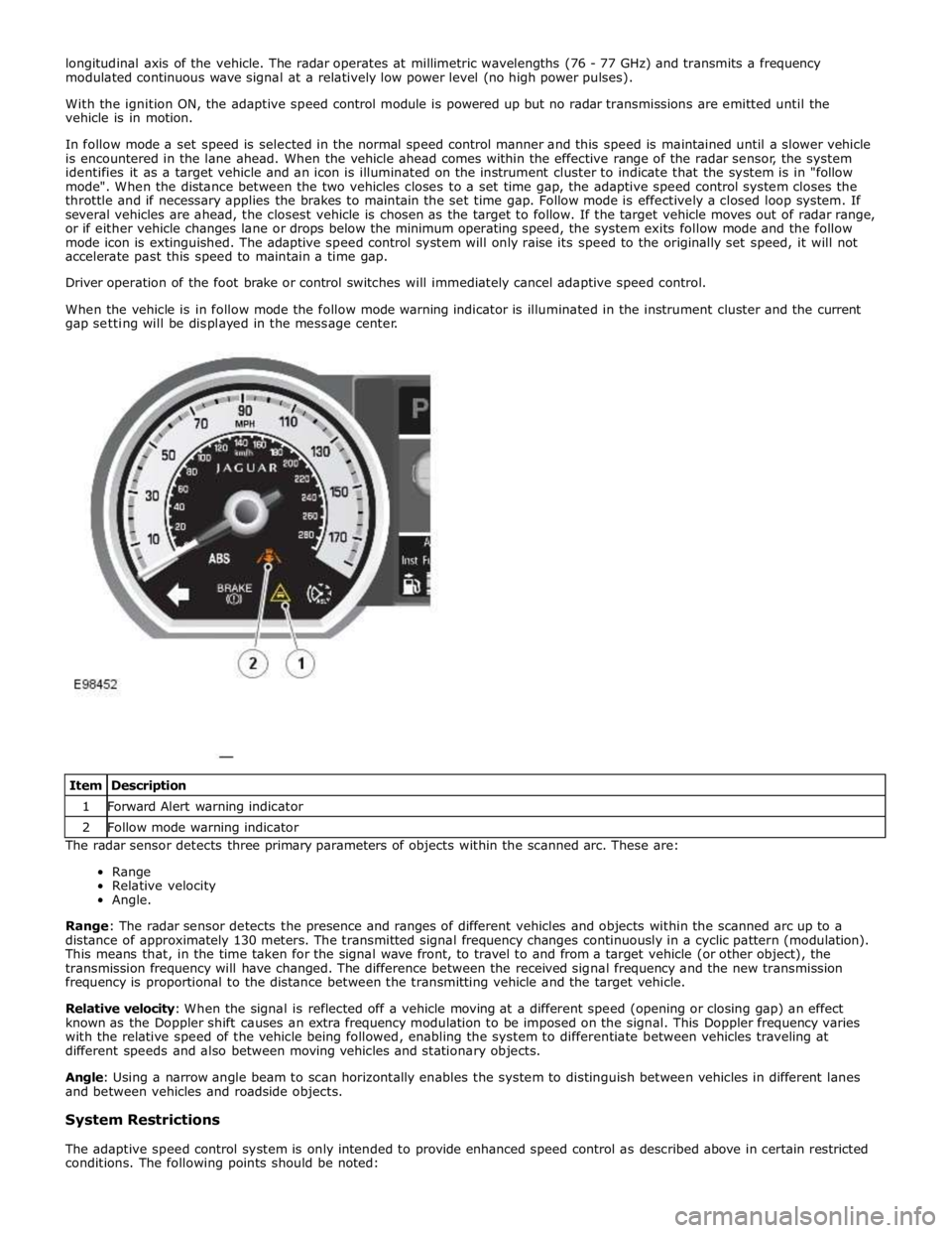
When the vehicle is in follow mode the follow mode warning indicator is illuminated in the instrument cluster and the current
gap setting will be displayed in the message center.
The radar sensor detects three primary parameters of objects within the scanned arc. These are:
Range
Relative velocity
Angle.
Range: The radar sensor detects the presence and ranges of different vehicles and objects within the scanned arc up to a
distance of approximately 130 meters. The transmitted signal frequency changes continuously in a cyclic pattern (modulation).
This means that, in the time taken for the signal wave front, to travel to and from a target vehicle (or other object), the
transmission frequency will have changed. The difference between the received signal frequency and the new transmission
frequency is proportional to the distance between the transmitting vehicle and the target vehicle.
Relative velocity: When the signal is reflected off a vehicle moving at a different speed (opening or closing gap) an effect
known as the Doppler shift causes an extra frequency modulation to be imposed on the signal. This Doppler frequency varies
with the relative speed of the vehicle being followed, enabling the system to differentiate between vehicles traveling at
different speeds and also between moving vehicles and stationary objects.
Angle: Using a narrow angle beam to scan horizontally enables the system to distinguish between vehicles in different lanes
and between vehicles and roadside objects.
System Restrictions
The adaptive speed control system is only intended to provide enhanced speed control as described above in certain restricted
conditions. The following points should be noted: Item Description 1 Forward Alert warning indicator 2 Follow mode warning indicator
Page 1648 of 3039

DTC Description Possible Causes Action C1A67-98 Forward Looking Sensor
- Component or system
over temperature
Speed control sensor
internal temperature
exceeded threshold
Allow system to cool. Note: This DTC will be cleared
automatically when environmental conditions allow P174E-81
Output Shaft
Speed/ABS Wheel
Speed Correlation -
Invalid serial data
received
Follow speed is
mis-calculated to too
high a value
Clear DTC and re-test U0001-88
High Speed CAN
Communication Bus -
Bus off
Vehicle CAN Bus off
condition
Carry out any pinpoint tests associated with this
DTC using the manufacturer approved diagnostic
system. Carry out CAN network integrity tests using
the manufacturer approved diagnostic system U0100-00
Lost Communications
With ECM/PCM "A" - No
sub type information
ECM missing message
Carry out any pinpoint tests associated with this
DTC using the manufacturer approved diagnostic
system. Check ECM for related DTCs and refer to the
relevant DTC Index U0101-00
Lost Communications
With TCM - No sub
type information
TCM missing message
Carry out any pinpoint tests associated with this
DTC using the manufacturer approved diagnostic
system. Check TCM for related DTCs and refer to the
relevant DTC Index U0103-00
Lost Communication
With Gear Shift Control
Module A - No sub type
information
No sub type information
Refer to the electrical circuit diagrams and check the
power and ground connections to the Transmission
Shift Module. Using the manufacturer approved
diagnostic system, complete a CAN network integrity
test. Refer to the electrical circuit diagrams and
check the CAN network between the Transmission
Shift Module and Speed Control Module U0103-87
Lost Communication
With Gear Shift Module
- Missing Message
Transmission shift
module missing message
Carry out any pinpoint tests associated with this
DTC using the manufacturer approved diagnostic
system. Check transmission shift module for related
DTCs and refer to the relevant DTC Index U0121-00
Lost Communication
With Anti-lock Brake
System (ABS) Control
Module - No sub type
information
ABS missing message
Carry out any pinpoint tests associated with this
DTC using the manufacturer approved diagnostic
system. Check ABS for related DTCs and refer to the
relevant DTC Index U0128-00
Lost Communications
With Park Brake Module
- No sub type
information
Parking brake missing
message
Carry out any pinpoint tests associated with this
DTC using the manufacturer approved diagnostic
system. Check parking brake module for related
DTCs and refer to the relevant DTC Index U0155-00
Lost Communications
With Instrument Panel
Cluster (IPC) Control
Module - No sub type
information
Instrument cluster
missing message
Carry out any pinpoint tests associated with this
DTC using the manufacturer approved diagnostic
system. Check instrument cluster for related DTCs
and refer to the relevant DTC Index U0300-00
Internal Control Module
Software
Incompatibility - No
sub type information
Invalid configuration
message is received
Re-configure the speed control module using the
manufacturer approved diagnostic system. Clear
DTCs and re-test. If DTC still logged, suspect
incorrect speed control module installed. Check and
install a new module as required, refer to new
module/component installation note at top of DTC
Index U0300-55
Internal Control Module
Software
Incompatibility - Not
configured
RJB - at least one of the
car configuration
parameters is not
configured
Re-configure the RJB using the manufacturer
approved diagnostic system www.JagDocs.com