2010 JAGUAR XFR window
[x] Cancel search: windowPage 726 of 3039

Hum
Continuous sound of varying frequencies, like a wire humming in the wind.
Knock
Heavy, loud repeating sound like a knock on a door.
Ping
Similar to knock, except at higher frequency.
Rattle
A sound suggesting looseness, such as marbles rolling around in a can.
Roar
Deep, long, prolonged sound like an animal, or winds and ocean waves.
Rumble
Low, heavy continuous sound like that made by wagons or thunder.
Scrape
Grating noise like one hard plastic part rubbing against another.
Squeak
High-pitched sound like rubbing a clean window.
Squeal
Continuous, high-pitched sound like running finger nails across a chalkboard.
Tap
Light, hammering sound like tapping pencil on edge of table. May be rhythmic or intermittent.
Whirr/Whine
High-pitched buzzing sound, like an electric motor or drill.
Whistle
Sharp, shrill sound, like wind passing a small opening.
Specific Steering System Noise Types
Belt Squeal
Belt squeal is a high frequency air-borne noise generated by slippage of the ribbed Vee belt on the power steering pump
pulley. Squeal increases with system loading and at full lock.
Clonk
Clonk is a structure-borne noise heard as a loose-sounding rattle or vibration coming from the steering column. Clonk can be
identified by driving and turning over cobblestones, rough roads, or high frequency bumps such as 25-50 mm tall tar strips.
Clonk requires a tie-rod load impact.
Column Knock
Column knock is a loose-sounding rattle or vibration generated by the steering column shaft contacting other portions of the
column assembly. The noise is both audible and tactile. Column knock is generated by driving over cobblestones or rough
pavement. It is not necessary to turn the steering wheel to create this noise.
Column Rattle
Column rattle is a metallic sounding noise created when applying a highly impulsive force to the steering wheel. Column rattle
is often used to combine the more general group of column noises including clonk and column knock. Column rattle noises can
be caused by clonk, knock, loose column components, bonus parts etc. A series of parked, straight-line driving, and cornering
tests should be carried out to isolate the source/sources.
Grinding/Scrape
Grinding is a low frequency noise in the column when the steering wheel is turned. It is generally caused by interference
Page 1360 of 3039
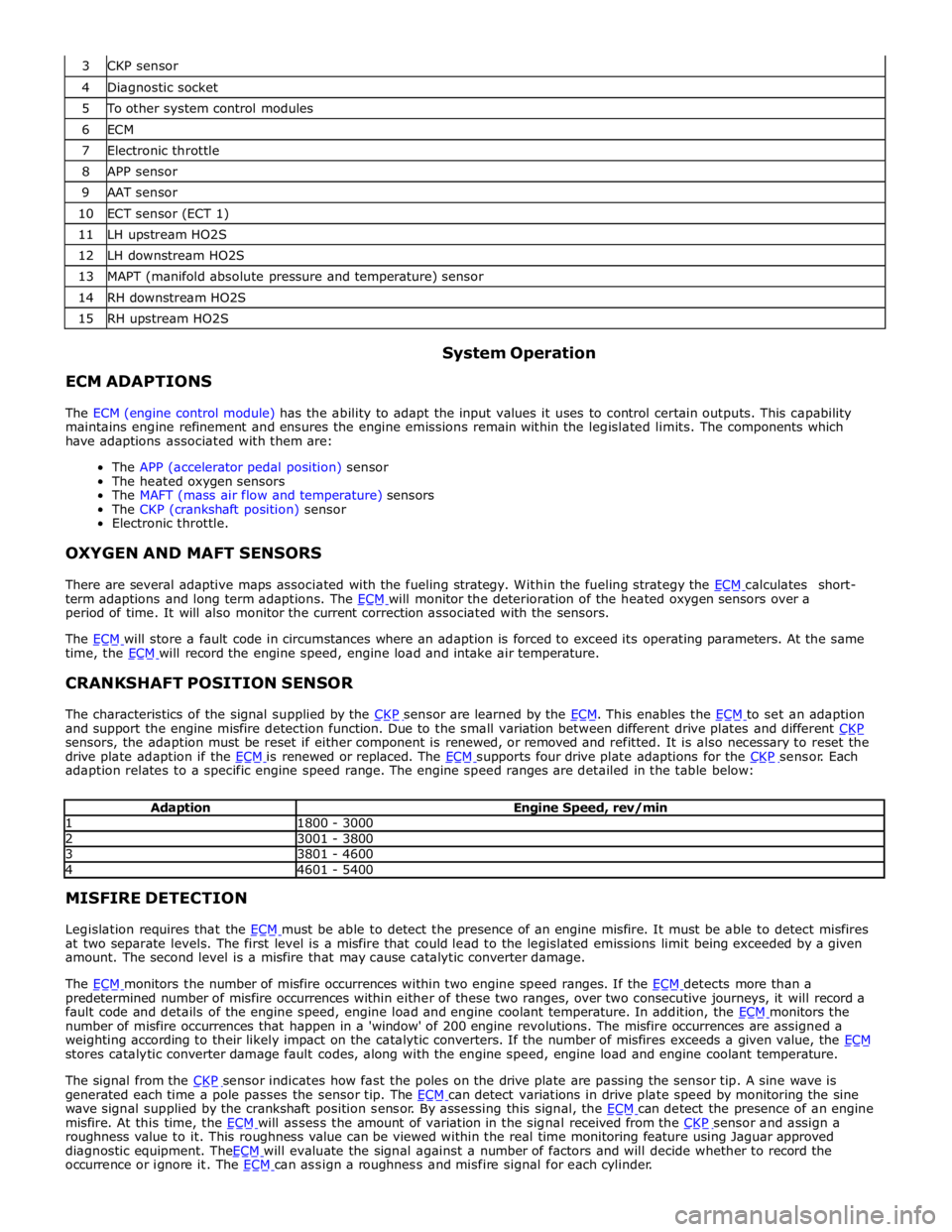
4 Diagnostic socket 5 To other system control modules 6 ECM 7 Electronic throttle 8 APP sensor 9 AAT sensor 10 ECT sensor (ECT 1) 11 LH upstream HO2S 12 LH downstream HO2S 13 MAPT (manifold absolute pressure and temperature) sensor 14 RH downstream HO2S 15 RH upstream HO2S
ECM ADAPTIONS System Operation
The ECM (engine control module) has the ability to adapt the input values it uses to control certain outputs. This capability
maintains engine refinement and ensures the engine emissions remain within the legislated limits. The components which
have adaptions associated with them are:
The APP (accelerator pedal position) sensor
The heated oxygen sensors
The MAFT (mass air flow and temperature) sensors
The CKP (crankshaft position) sensor
Electronic throttle.
OXYGEN AND MAFT SENSORS
There are several adaptive maps associated with the fueling strategy. Within the fueling strategy the ECM calculates short-term adaptions and long term adaptions. The ECM will monitor the deterioration of the heated oxygen sensors over a period of time. It will also monitor the current correction associated with the sensors.
The ECM will store a fault code in circumstances where an adaption is forced to exceed its operating parameters. At the same time, the ECM will record the engine speed, engine load and intake air temperature.
CRANKSHAFT POSITION SENSOR
The characteristics of the signal supplied by the CKP sensor are learned by the ECM. This enables the ECM to set an adaption and support the engine misfire detection function. Due to the small variation between different drive plates and different CKP sensors, the adaption must be reset if either component is renewed, or removed and refitted. It is also necessary to reset the
drive plate adaption if the ECM is renewed or replaced. The ECM supports four drive plate adaptions for the CKP sensor. Each adaption relates to a specific engine speed range. The engine speed ranges are detailed in the table below:
Adaption Engine Speed, rev/min 1 1800 - 3000 2 3001 - 3800 3 3801 - 4600 4 4601 - 5400 MISFIRE DETECTION
Legislation requires that the ECM must be able to detect the presence of an engine misfire. It must be able to detect misfires at two separate levels. The first level is a misfire that could lead to the legislated emissions limit being exceeded by a given
amount. The second level is a misfire that may cause catalytic converter damage.
The ECM monitors the number of misfire occurrences within two engine speed ranges. If the ECM detects more than a predetermined number of misfire occurrences within either of these two ranges, over two consecutive journeys, it will record a
fault code and details of the engine speed, engine load and engine coolant temperature. In addition, the ECM monitors the number of misfire occurrences that happen in a 'window' of 200 engine revolutions. The misfire occurrences are assigned a
weighting according to their likely impact on the catalytic converters. If the number of misfires exceeds a given value, the ECM stores catalytic converter damage fault codes, along with the engine speed, engine load and engine coolant temperature.
The signal from the CKP sensor indicates how fast the poles on the drive plate are passing the sensor tip. A sine wave is generated each time a pole passes the sensor tip. The ECM can detect variations in drive plate speed by monitoring the sine wave signal supplied by the crankshaft position sensor. By assessing this signal, the ECM can detect the presence of an engine misfire. At this time, the ECM will assess the amount of variation in the signal received from the CKP sensor and assign a roughness value to it. This roughness value can be viewed within the real time monitoring feature using Jaguar approved
diagnostic equipment. TheECM will evaluate the signal against a number of factors and will decide whether to record the occurrence or ignore it. The ECM can assign a roughness and misfire signal for each cylinder.
Page 1683 of 3039
Published: 11-May-2011
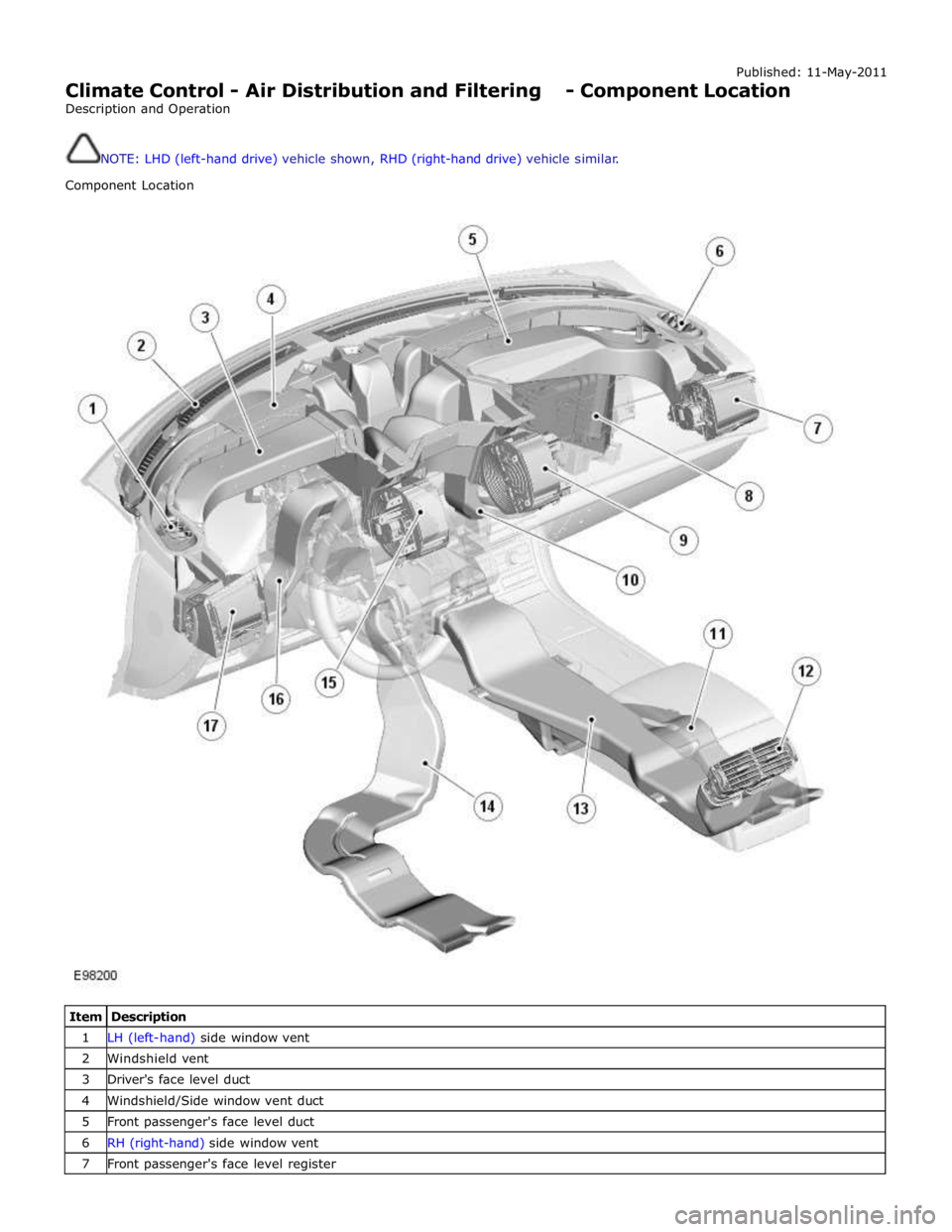
Climate Control - Air Distribution and Filtering - Component Location
Description and Operation
NOTE: LHD (left-hand drive) vehicle shown, RHD (right-hand drive) vehicle similar.
Component Location
Item Description 1 LH (left-hand) side window vent 2 Windshield vent 3 Driver's face level duct 4 Windshield/Side window vent duct 5 Front passenger's face level duct 6 RH (right-hand) side window vent 7 Front passenger's face level register
Page 1687 of 3039

7 RH (right-hand) outer face level register 8 RH inner face level register 9 LH (left-hand) inner face level register 10 LH outer face level register 11 Face/Feet distribution stepper motor 12 RH temperature blend stepper motor 13 Windshield (defrost) distribution stepper motor 14 LH temperature blend stepper motor
Face Level Registers System Operation
Operation of the face level registers is controlled by the ATC module, using LIN bus messages to the integral stepper motors. The four registers operate together in both the opening and closing phases.
The face level registers can be selected to run in one of two modes; 'automatic' or 'always open'. The mode is selected on the
climate control screen of the TSD.
Refer to: Navigation System (415-01 Information and Entertainment System, Description and Operation).
In the automatic mode, operation of the face level registers is synchronized with the engine START/STOP button. When the
engine starts the ATC module opens the registers. When the engine stops, the ATC module closes the registers.
If a face level register is fouled, when it receives an open or close request, the register concerned makes a number of
attempts to reach the requested position. If the register still does not move, it is left in the fouled position. The remaining
registers will continue to open and close as normal.
The automatic mode is disabled when the climate control system is off. The ATC module closes the registers if they are open in the automatic mode and the climate control system is selected off.
Diagnostics
If a fault occurs with the face level registers, a DTC (diagnostic trouble code) is stored in the ATC module. The DTC can be read using the Jaguar approved diagnostic system. The Jaguar approved diagnostic system can also initiate a self test routine
to check the operation of the face level registers.
Refer to: Climate Control System (412-00 Climate Control System - General Information, Diagnosis and Testing).
Air Ducts Component Description
The air ducts distribute air from the heater assembly to the registers and vents in the instrument panel and the center floor
console. Air ducts also direct air from the heater assembly into the front and rear footwells.
Registers and Vents
The registers control the flow and direction of air from the air ducts. The instrument panel contains four face level registers;
one at each end and two mounted centrally. For the rear seat occupants, two registers are installed in the rear face of the
center floor console. All of the registers incorporate vertical and horizontal directional vane adjustment and full air flow
adjustment down to zero.
The four face level registers in the instrument panel each contain an integral stepper motor. The stepper motors enable the
registers to rotate between the open and closed positions. In the open position, the registers have normal appearance and
functionality. In the closed position, the registers present a smooth surface flush with the surrounding instrument panel.
The vents are fixed outlets. There are four vents in the upper surface of the instrument panel; one in each end to direct air
onto the side windows and two along the front edge to direct air onto the windshield.
Central Face Level Registers
www.JagDocs.com
Page 1706 of 3039
Climate Control - Control Components - Overview
Description and Operation
Overview Published: 11-May-2011
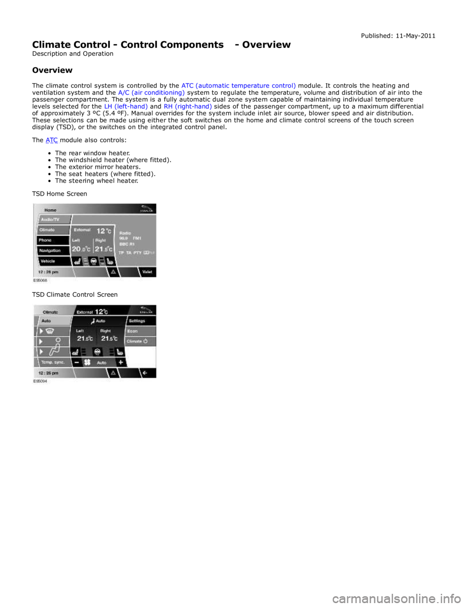
The climate control system is controlled by the ATC (automatic temperature control) module. It controls the heating and
ventilation system and the A/C (air conditioning) system to regulate the temperature, volume and distribution of air into the
passenger compartment. The system is a fully automatic dual zone system capable of maintaining individual temperature
levels selected for the LH (left-hand) and RH (right-hand) sides of the passenger compartment, up to a maximum differential
of approximately 3 ºC (5.4 ºF). Manual overrides for the system include inlet air source, blower speed and air distribution.
These selections can be made using either the soft switches on the home and climate control screens of the touch screen
display (TSD), or the switches on the integrated control panel.
The ATC module also controls: The rear window heater.
The windshield heater (where fitted).
The exterior mirror heaters.
The seat heaters (where fitted).
The steering wheel heater.
TSD Home Screen
TSD Climate Control Screen
Page 1707 of 3039
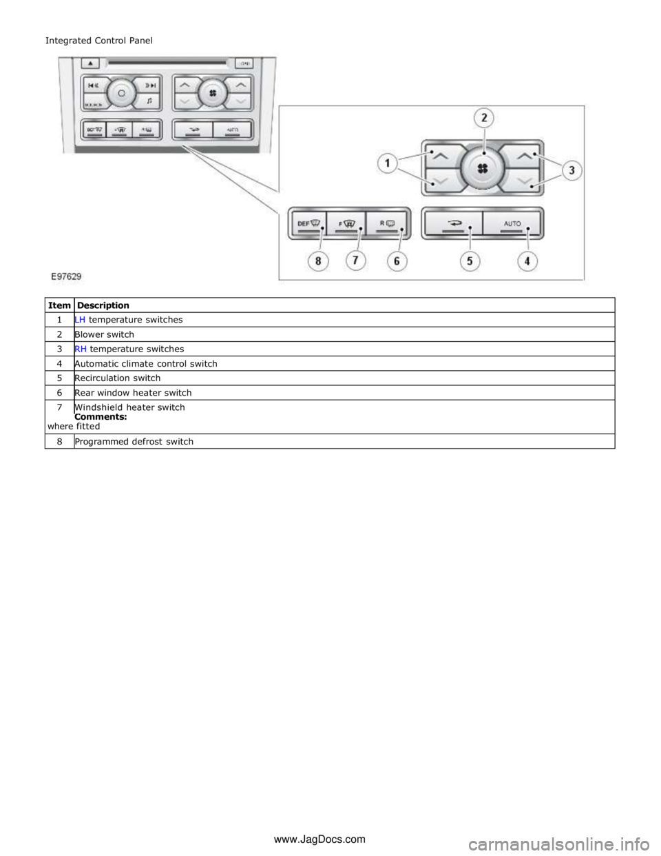
1 LH temperature switches 2 Blower switch 3 RH temperature switches 4 Automatic climate control switch 5 Recirculation switch 6 Rear window heater switch 7 Windshield heater switch Comments:
where fitted 8 Programmed defrost switch Integrated Control Panel
www.JagDocs.com
Page 1710 of 3039
control switch on the integrated control panel or the + and - soft buttons on the touch screen display (TSD). The ATC module also adjusts blower speed to compensate for the ram effect on inlet air produced by forward movement of the vehicle. As
vehicle speed and ram effect increases, blower motor speed is reduced, and vice versa.
Air Distribution Control
Two air distribution doors are used to direct air into the passenger compartment. The doors are operated by stepper motors,
which are controlled by the ATC module using LIN bus messages.
When the A/C system is in automatic mode, the ATC module automatically controls air distribution into the passenger compartment in line with its 'comfort' algorithm. Automatic control is overridden if any of the TSD air distribution soft buttons
are selected. Air distribution in the passenger compartment will remain as selected until the 'Auto' switch is pressed or a
different manual selection is made.
A/C Compressor Control
When A/C is selected the ATC module maintains the evaporator at an operating temperature that varies with the passenger compartment cooling requirements. If the requirement for cooled air decreases, the ATC module raises the evaporator operating temperature by reducing the flow of refrigerant provided by the A/C compressor. The ATC module closely controls the rate of temperature increase to avoid introducing moisture into the passenger compartment.
If the requirement for cooled air increases, the ATC module lowers the evaporator operating temperature by increasing the flow of refrigerant provided by the A/C compressor.
When A/C is off, the compressor current signal supplied by the ATC module holds the A/C compressor solenoid valve in the minimum flow position, effectively switching off the A/C function.
The ATC module incorporates limits for the operating pressure of the refrigerant system. If the system approaches the high pressure limit, the compressor current signal is progressively reduced until the system pressure decreases. If the system falls
below the low pressure limit, the compressor current signal is held at its lowest setting so that the A/C compressor is maintained at its minimum stroke. This avoids depletion of the lubricant from the A/C compressor.
A/C Compressor Torque
The ATC module transmits refrigerant pressure and A/C compressor current values to the ECM (engine control module) over the medium speed then high speed CAN bus, using the CJB as a gateway. The ECM uses these values to calculate the torque being used to drive the A/C compressor. The ECM compares the calculated value with its allowable value and if necessary forces the ATC module to inhibit the A/C compressor by transmitting the 'ACClutchInhibit' CAN message. This forces the ATC module to reduce the drive current to the A/C compressor solenoid valve, which reduces refrigerant flow. This in turn reduces the torque required to drive the A/C compressor.
By reducing the maximum A/C compressor torque, the ECM is able to reduce the load on the engine when it needs to maintain vehicle performance or cooling system integrity.
Cooling Fan Control
The ATC module determines the amount of condenser cooling required from the refrigerant pressure sensor, since there is a direct relationship between the temperature and pressure of the refrigerant. The cooling requirement is broadcast to the ECM on the medium speed CAN bus. The ECM then controls the temperature of the condenser using the cooling fan.
Programmed Defrost
The programmed defrost DEF switch is located on the integrated control panel. When the switch is pressed, the ATC module instigates the programmed defrost function. When selected, the ATC module configures the system as follows:
Automatic mode off.
A/C on. Selected temperature unchanged.
Air inlet set to fresh air.
Air distribution set to windshield.
Blower speed set to level 6.
Windshield heater (where fitted) and rear window heater on.
The programmed defrost function can be cancelled by one of the following:
Selecting any air distribution switch on the TSD.
Pressing the AUTO switch on the integrated control panel.
A second press of the DEF button.
Switching the ignition OFF.
The blower speed can be adjusted without terminating the programmed defrost function.
Rear Window Heater
Rear window heater operation is only enabled when the engine is running. The ATC module controls operation of the rear window heater using a relay in the RJB. When rear window heater operation is required, the ATC module broadcasts a message to the RJB on the medium speed CAN bus. On receipt of the message, the RJB energizes the relay by providing a ground path for the relay coil. This allows a battery feed to flow across the relay to power the rear window heater element.
Page 1711 of 3039
rear window heater switch is pressed or the engine stops.
Automatic operation during a journey is initiated when low ambient air temperatures are experienced and the vehicle has been
travelling for a set period of time above a threshold speed. In this instance, no feedback is given to the driver to inform him
the rear window heater is operational (the switch LED is not illuminated). The duration of heater operation is variable depending on the ambient air temperature, vehicle speed and the amount of time the vehicle has been travelling.
Windshield Heater (Where Fitted)
Windshield heater operation is only enabled when the engine is running. The ATC module controls operation of the windshield heater using two relays in the EJB (engine junction box). When windshield heater operation is required, the ATC module broadcasts a message to the CJB on the medium speed CAN bus. On receipt of the message, the CJB energizes the relays by providing a ground path for both relay coils. This allows a battery feed to flow across the relays to power the windshield left
and right heater elements.
There are two modes of windshield heater operation; manual and automatic.
Manual operation is activated by pressing the windshield heater switch on the integrated control panel. When the switch is
pressed, the status LED in the switch illuminates and the windshield heater elements are energized. Manual operation is discontinued when the windshield heater switch is pressed a second time, 5 minutes have elapsed (the heating phase), or the
engine stops. If manual operation is discontinued by the engine stopping, the previous heating phase is resumed if the engine
is re-started within 30 seconds.
There are two variants of automatic operation; automatic operation at the start of a journey and automatic operation during a
journey.
Automatic operation at the start of a journey is initiated if the ambient air temperature is below 5 °C (41 °F). In this instance,
the switch LED is illuminated and the heater elements are energized for 6.5 minutes. Automatic operation is discontinued if the windshield heater switch is pressed or the engine stops.
Automatic operation during a journey is initiated when low ambient air temperatures are experienced and the vehicle has been
travelling for a set period of time above a threshold speed. In this instance, no feedback is given to the driver to inform him
the windshield heater is operational (the switch LED is not illuminated) and the duration of operation is variable depending upon the ambient air temperature, vehicle speed and the amount of time the vehicle has been travelling.
Exterior Mirror Heaters
Operation of the exterior mirror heaters is fully automatic and not controllable by the driver. Exterior mirror heater operation is
determined by ambient air temperature and windshield wiper status. When ambient air temperature reaches a pre-determined
level, the ATC module broadcasts an exterior mirror heating request to the door modules over the medium speed CAN bus. On receipt of this message, the door modules provide feed and ground connections to both exterior mirror heater elements.
The amount of time the exterior mirror heaters are operational increases if the windshield wipers are switched on. This ensures
the mirrors remain mist free in damp and wet conditions, where there is an increased risk of misting.
Seat Heaters (Where Fitted)
There are four seat heater settings available; off, 1, 2 and 3, which can be selected on the home and climate control screens
of the TSD. The heat setting is relayed to the vehicle occupants through a graduated display on the TSD.
Operation of the heated seats is controlled by the ATC module. When the ATC module receives a heating request from the TSD, it broadcasts a message to the CJB over the medium speed CAN bus. The CJB then provides a hardwired 12 V supply to the three heater elements in the related front seat. The heater elements, two in the seat cushion and one in the seat squab,
are wired in series. The ATC module monitors seat temperature using a temperature sensor located in each seat cushion. The CJB provides the temperature sensors with a 5 V supply. The level of the returned voltage back to the CJB is proportional to the seat temperature. The value of the return signal is broadcast to the ATC module, over the medium speed CAN bus, which allows it to control the seat temperature to the required level. The ATC module will suspend or disable operation of the seat heaters if any of the following occur:
Battery voltage exceeds 16.5 ± 0.3 V for more than 5 seconds. Seat heating is re-enabled when battery voltage
decreases to 16.2 ± 0.3 V.
If a short or open circuit is detected.
If the seat heat temperature rises significantly above the target temperature setting.
The graduated display on the TSD remains illuminated until the seat heaters are turned off or the engine stops. If the engine
is restarted within 30 seconds the seat heater resumes the previous heating level.