2010 JAGUAR XFR window
[x] Cancel search: windowPage 1802 of 3039

DTC Description Possible Cause Action programming state
Attempted to program a non
default key
Instrument cluster Cold init
whilst in Ignition On state,
without key being present in
the SCU
Race condition caused by
closing driver door and
pressing the start button
within a small time window
Passive Key search function
from last door closed and key
inserted in the SCU instrument cluster. Design condition - advise customer of
starting sequence. Design condition - determine customer
transponder key usage B1B0187 Key Transponder
LIN fault
Instrument cluster power and
ground supply circuits - short,
open circuit
Smartcard docking station
power and ground supply
circuits - short, open circuit Carry out any pinpoint tests associated with this DTC using
the manufacturer approved diagnostic system. Check LIN
communications between smartcard docking station and
instrument cluster. Refer to the electrical circuit diagrams
and check smartcard docking station power and ground
supply circuits for short, open circuit and instrument cluster
power and ground supply circuits for short, open circuit B1B3305
Target I.D.
Transfer
CAN fault
ECM ignition, power and
ground supply circuits - short,
open circuit
Instrument cluster power and
ground supply circuits - short,
open circuit
ECM or instrument cluster
incorrectly configured Carry out any pinpoint tests associated with this DTC using
the manufacturer approved diagnostic system. Check CAN
communications between ECM and instrument cluster. Refer
to electrical circuit diagrams and check ECM ignition, power
and ground supply circuits for short, open circuit and
instrument cluster power and ground supply circuits for short,
open circuit. Perform the Immobilisation application from the
Set-up menu using the manufacturer approved diagnostic
system B1B3362
Target I.D.
Transfer
CAN fault
ECM ignition, power and
ground supply circuits - short,
open circuit
Instrument cluster power and
ground supply circuits - short,
open circuit
Incorrect ECM or instrument
cluster installed
Synchronisation error following
re-programming
Noise/EMC related error Carry out any pinpoint tests associated with this DTC using
the manufacturer approved diagnostic system. Check CAN
communications between ECM and instrument cluster. Refer
to electrical circuit diagrams and check ECM ignition, power
and ground supply circuits for short, open circuit and
instrument cluster power and ground supply circuits for short,
open circuit. Check correct ECM and instrument cluster
installed. Perform the Immobilisation application from the
Set-up menu using the manufacturer approved diagnostic
system. Check CAN network for interference/EMC related
issues B1B3364
Target
identification
transfer
Algorithm based failure -
signal plausibility failure
CAN fault
ECM ignition, power and
ground supply circuits - short,
open circuit
Instrument cluster power and
ground supply circuits - short,
open circuit
electronic steering column lock
status incomplete
Race condition caused by
closing driver door and
pressing the start button
within a small time window If the customer has not reported a non start issue, clear the
DTC and check vehicle starts correctly. If a non start has
been reported run the manufacturers approved diagnostic
system Start Authorisation Application and follow the actions
required for this DTC. Carry out any pinpoint tests associated
with this DTC using the manufacturer approved diagnostic
system. Check CAN communications between ECM and
instrument cluster. Refer to electrical circuit diagrams and
check ECM ignition, power and ground supply circuits for
short, open circuit and instrument cluster power and ground
supply circuits for short, open circuit. Check electronic
steering column lock operation. Advise customer of starting
sequence and to allow time to elapse between closing door
and pressing start button. B1B3387
Target I.D.
Transfer
CAN fault
ECM ignition, power and
ground supply circuits - short,
open circuit
Instrument cluster power and
ground supply circuits - short,
open circuit
Low battery voltage Carry out any pinpoint tests associated with this DTC using
the manufacturer approved diagnostic system. Check CAN
communications between ECM and instrument cluster. Refer
to electrical circuit diagrams and check ECM ignition, power
and ground supply circuits for short, open circuit and
instrument cluster power and ground supply circuits for short,
open circuit. Check battery is in serviceable condition and is
fully charged, check terminals etc www.JagDocs.com
Page 1903 of 3039
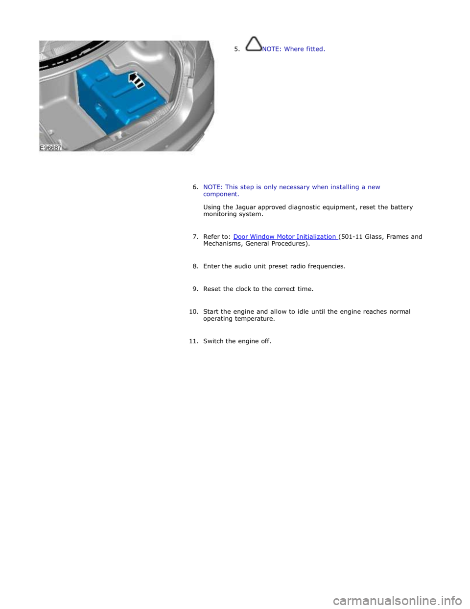
5. NOTE: Where fitted.
6. NOTE: This step is only necessary when installing a new
component.
Using the Jaguar approved diagnostic equipment, reset the battery
monitoring system.
7. Refer to: Door Window Motor Initialization (501-11 Glass, Frames and Mechanisms, General Procedures).
8. Enter the audio unit preset radio frequencies.
9. Reset the clock to the correct time.
10. Start the engine and allow to idle until the engine reaches normal
operating temperature.
11. Switch the engine off.
Page 1907 of 3039
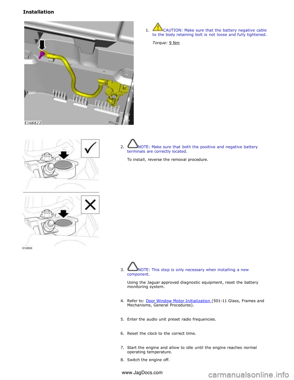
Installation
1. CAUTION: Make sure that the battery negative cable
to the body retaining bolt is not loose and fully tightened.
Torque: 9 Nm
2. NOTE: Make sure that both the positive and negative battery
terminals are correctly located.
To install, reverse the removal procedure.
3. NOTE: This step is only necessary when installing a new
component.
Using the Jaguar approved diagnostic equipment, reset the battery
monitoring system.
4. Refer to: Door Window Motor Initialization (501-11 Glass, Frames and Mechanisms, General Procedures).
5. Enter the audio unit preset radio frequencies.
6. Reset the clock to the correct time.
7. Start the engine and allow to idle until the engine reaches normal
operating temperature.
8. Switch the engine off. www.JagDocs.com
Page 1945 of 3039

player is only compatible with standard CD's. All other versions of CD player are compatible with standard CDs and CDs with MP3 or WMA (windows media audio) files.
A portable audio module allows for the connection of a range of portable audio devices to the car’s audio system. The portable
audio module is controlled through the IAM (integrated audio module) and Touch-screen with play back through the car’s
speaker system. The introduction of this system allows the user to import their personal portable media player to interface
with the car, including iPod and other MP3 players, or USB mass storage devices such as memory sticks. MP3 players can also
be controlled through the Touch-screen if they are configured as mass storage devices. Details of how to do this will be
contained in the manufacturers instructions.
The chosen audio device can be plugged into the car using an interface panel located in the floor console between the front
seats. The interface includes a 3.5mm auxiliary jack-plug socket, a 12-volt power supply, a dedicated iPod connector with
charging function, plus a USB2 connector which allows connectivity for a wide variety of USB devices. The USB port also
provides a charging function although it does not support a USB hub. The maximum charging current supplied is 500ma. The
user can connect an iPod and USB device at the same time, changing the source via the Touch-screen. The non selected source
will still charge.
The Jaguar Sound System is the basic audio system which comprises of an IAM (integrated audio module) with no external
amplifier and 8 speakers.
The Jaguar 320W Premium Sound System has the addition of an AUD 8 power amplifier and a 9 speaker system.
The Bowers & Wilkins 440w Surround Sound System additions include an AUD 12 power amplifier, a Dolby Pro-Logic 2 7.1
Surround Sound System, and 14 speakers.
DAB (digital audio broadcasting) is available for most European markets and gives access to digital radio channels for better
sound quality and enhanced functionality depending on local service availability. The DAB (digital audio broadcasting) module
is located in the luggage compartment. The system receives reception signals from the following sources to ensure optimum
signal strength.
DAB band L antenna located in the roof pod antenna module
DAB band III antenna located in the heated rear window.
For NAS vehicles the digital format adopted is satellite radio which specifically links to the Sirius network. The system operates
in the S-band frequency range, and as a result of the use of satellite transmission, has the ability to provide CD quality audio broadcasts over very large areas (typically continents). The satellite radio receiver is located in the luggage compartment. The
system receives reception signals from the satellite radio antenna located in the roof pod module.
Primary user control of the audio system is via the ICP (integrated control panel) and the Touch-screen which are located in the
center of the instrument panel. Control signals from the ICP (integrated control panel) are relayed on the medium speed CAN
(controller area network) bus to the ICM (information control module). The ICM (information control module) relays the control
signals to the rest of the audio system on the MOST (media oriented systems transport) ring. The ICM (information control
module) is the timing master for the MOST (media oriented systems transport) ring and also hosts a gateway function between
the medium speed CAN bus and the MOST (media oriented systems transport) ring. Audio output signals on the Jaguar 320W Premium Sound System and Bowers & Wilkins 440W Surround Sound System are sent on the MOST (media oriented systems
transport) ring from the IAM (integrated audio module) to the power amplifier for speaker output. www.JagDocs.com
Page 1952 of 3039
automatically detects the CD format of the source (standard CD, MP3 or WMA files) and offers a full range of options, presenting folders on the touch-screen, listed by albums and tracks, to browse as on a PC. Both versions have mix and repeat
functions and the six-disc version displays disc names.
The IAM communicates on the MOST system with the rest of the audio system. If the IAM is replaced it must be configured as
a new module using the Jaguar approved diagnostic equipment.
Calibration of the IAM using the Jaguar approved diagnostic equipment enables updates to be downloaded as new technology
becomes available or any fault concerns require software updates.
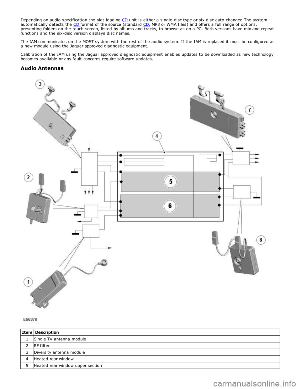
Audio Antennas
Item Description 1 Single TV antenna module 2 RF filter 3 Diversity antenna module 4 Heated rear window 5 Heated rear window upper section
Page 1953 of 3039
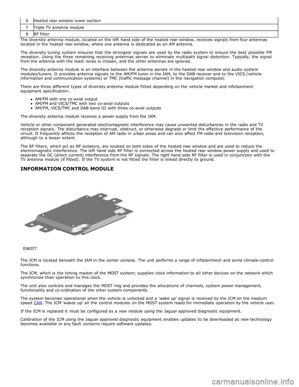
7 Triple TV antenna module 8 RF filter The diversity antenna module, located on the left hand side of the heated rear window, receives signals from four antennas
located in the heated rear window, where one antenna is dedicated as an AM antenna.
The diversity tuning system ensures that the strongest signals are used by the radio system to ensure the best possible FM
reception. Using the three remaining receiving antennas serves to eliminate multipath signal distortion. Typically, the signal
from the antenna with the least noise is chosen, and the other antennas are ignored.
The diversity antenna module is an interface between the antenna aerials in the heated rear window and audio system
modules/tuners. It provides antenna signals to the AM/FM tuner in the IAM, to the DAB receiver and to the VICS (vehicle
information and communication systems) or TMC (traffic message channel) in the navigation computer.
There are three different types of diversity antenna module fitted depending on the vehicle market and infotainment
equipment specification:
AM/FM with one co-axial output
AM/FM and VICS/TMC with two co-axial outputs
AM/FM, VICS/TMC and DAB band III with three co-axial outputs
The diversity antenna module receives a power supply from the IAM.
Vehicle or other component generated electromagnetic interference may cause unwanted disturbances in the radio and TV
reception signals. The disturbance may interrupt, obstruct, or otherwise degrade or limit the effective performance of the
circuit. It frequently affects the reception of AM radio in urban areas and can also affect FM radio and television reception,
although to a lesser extent.
The RF filters, which act as RF isolators, are located on both sides of the heated rear window and are used to reduce the
electromagnetic interference. The left hand side RF filter is connected across the heated rear window power supply and used to
separate the DC (direct current) interference from the RF signals. The right hand side RF filter is used in conjunction with the
TV antenna module (if fitted). If the TV system is not fitted the filter is linked directly to ground.
INFORMATION CONTROL MODULE
The ICM is located beneath the IAM in the center console. The unit performs a range of infotainment and some climate-control
functions.
The ICM, which is the timing master of the MOST system; supplies clock information to all other devices on the network which
synchronize their operation to this clock.
The unit also controls and manages the MOST ring and provides the allocations of channels, system power management,
functionality and co-ordination of the other system components.
The system becomes operational when the vehicle is unlocked and a 'wake up' signal is received by the ICM on the medium
speed CAN. The ICM 'wakes up' all the control modules on the MOST system ready for immediate operation by the vehicle user. If the ICM is replaced it must be configured as a new module using the Jaguar approved diagnostic equipment.
Calibration of the ICM using the Jaguar approved diagnostic equipment enables updates to be downloaded as new technology
becomes available or any fault concerns require software updates.
Page 1957 of 3039
NOTE: When the vehicle DAB radio is first used the system will not receive any digital stations until the auto-tune
function has been completed.
Digital radio channels are organized into groups called ensembles (also known as multiplexes). Some individual channels may
also provide a number of subchannels. For example, if several sports events are being held simultaneously, the channel may
temporarily choose to broadcast each different event on a separate subchannel.
DAB is broadcast across Europe, Canada and parts of Asia. System transmission is via a terrestrial network, on two separate
broadcasting bands:
DAB band-L
DAB band III
The DAB system requires additional components to be added to the audio system. DAB antennas and a receiver are fitted to
allow reception of the service.
Operation of the DAB system is the same as the radio operation with selections made through the touch-screen and ICP to
access and navigate the system functions.
The DAB receiver is a dedicated tuner which is controlled by the ICM on the MOST ring. The receiver processes the signals from
the DAB antennas. Information is transmitted on the MOST ring and processed by the ICM. The processed information is sent
out to the power amplifier or IAM (with internal amplifier) and broadcast through the speaker system.
No configuration procedure is required if the DAB receiver is replaced. Calibration of the DAB receiver using the Jaguar
approved diagnostic equipment enables updates to be downloaded as new technology becomes available or any fault concerns
require software updates.
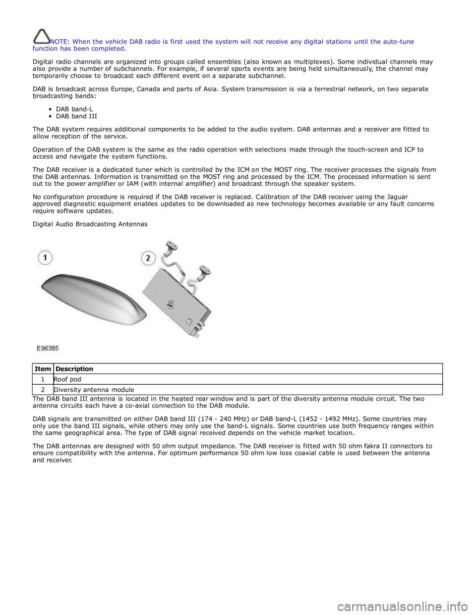
Digital Audio Broadcasting Antennas
Item Description 1 Roof pod 2 Diversity antenna module The DAB band III antenna is located in the heated rear window and is part of the diversity antenna module circuit. The two
antenna circuits each have a co-axial connection to the DAB module.
DAB signals are transmitted on either DAB band III (174 - 240 MHz) or DAB band-L (1452 - 1492 MHz). Some countries may
only use the band III signals, while others may only use the band-L signals. Some countries use both frequency ranges within
the same geographical area. The type of DAB signal received depends on the vehicle market location.
The DAB antennas are designed with 50 ohm output impedance. The DAB receiver is fitted with 50 ohm fakra II connectors to
ensure compatibility with the antenna. For optimum performance 50 ohm low loss coaxial cable is used between the antenna
and receiver.
Page 1970 of 3039
1 The 'not epad' facil it y allows voi ce not es t o be recorded. Nametags for phone di al ing and navigati on locati ons allow the
s ys t em t o be personali zed and there is a hel p and t utori al funct ion to provi de advi ce on us ing t he s ys t em.
The s ys t em al lows t he vehi cl e us er to concent rat e ful ly on drivi ng the vehicle, wi thout any need to di vert t hei r eyes from
t he road ahead in order to check informat ion read out s on t he vehi cle i nst rument panel i nformati on uni ts . The voice control
s ys t em al so feeds back audibl e informat ion t o t he vehi cle us er.
JaguarVoi ce is a key component of t he phone sys tem, al lowi ng hands free control and us e of t he Bluet oot h® enabled
phone.
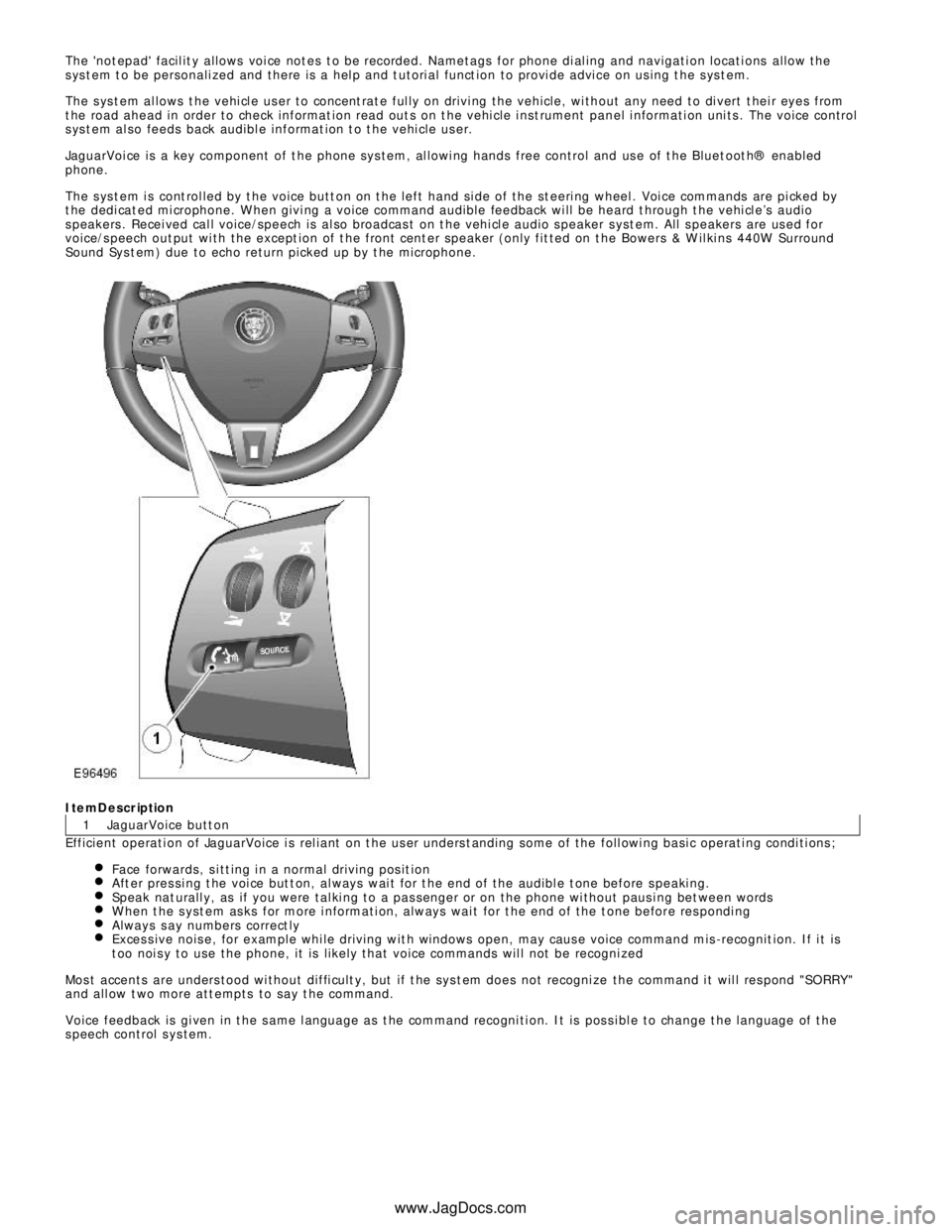
The s ys t em i s cont rol led by t he voice butt on on t he left hand si de of the st eeri ng wheel . Voi ce commands are pi cked by
t he dedi cat ed mi crophone. W hen givi ng a voice command audible feedback wi ll be heard t hrough t he vehi cl e’s audio
s peakers . Recei ved cal l voice/speech is al so broadcas t on t he vehi cl e audio s peaker s yst em. All s peakers are us ed for
voice/s peech out put wi th the except ion of t he front cent er speaker (only fit ted on t he Bowers & W il ki ns 440W Surround
Sound Sys t em) due to echo return picked up by t he microphone.ItemDescription
JaguarVoice butt on
Efficient operati on of JaguarVoice i s rel iant on t he us er unders t anding some of the foll owi ng basi c operati ng condi ti ons ;
Face forwards, s i tt ing i n a normal driving pos it ionAft er pres si ng t he voi ce but t on, al ways wai t for t he end of the audibl e t one before s peaki ng.Speak nat urall y, as if you were tal ki ng to a pas senger or on the phone wi thout paus i ng bet ween wordsW hen t he s yst em as ks for more i nformati on, always wai t for t he end of the t one before res pondi ngAlways s ay numbers correct lyExces s ive nois e, for example whi le driving wit h windows open, may caus e voice command mis -recognit ion. If i t is
t oo noi s y to use the phone, it is li kel y that voice commands wil l not be recogni zedMos t accents are unders tood wi thout diffi cult y, but if t he sys t em does not recogni ze the command i t wil l res pond "SORRY "
and all ow t wo more att empts to say t he command.
Voice feedback is gi ven in t he s ame l anguage as t he command recogni ti on. It is pos s i bl e to change t he language of t he
s peech control s ys tem.
www.JagDocs.com