2010 JAGUAR XFR light
[x] Cancel search: lightPage 2089 of 3039

DTC Description Possible Cause Action B115B11 Driver Seat Heater
Driver seat heater supply circuit
- short to ground Carry out any pinpoint tests associated with this DTC
using the manufacturer approved diagnostic system.
Refer to the electrical circuit diagrams and check driver
seat heater supply circuit for short to ground B115B15 Driver Seat Heater
Driver seat heater supply circuit
- short to power, open circuit Carry out any pinpoint tests associated with this DTC
using the manufacturer approved diagnostic system.
Refer to the electrical circuit diagrams and check driver
seat heater supply circuit for short to power, open circuit B117513
Driver Door Ajar
Switch
Driver door ajar switch signal
circuit - open circuit Refer to the electrical circuit diagrams and check driver
door ajar switch signal circuit for open circuit B117613
Passenger Door
Ajar Switch
Passenger door ajar switch
signal circuit - open circuit Refer to the electrical circuit diagrams and check
passenger door ajar switch signal circuit for open circuit B117712
Screenwash Level
Switch
Screenwash level switch signal
circuit - short to power Refer to the electrical circuit diagrams and check
screenwash level switch signal circuit for short to power B11C013
Driver Side Rear
Door Ajar Switch
Left rear door ajar switch signal
circuit - open circuit Refer to the electrical circuit diagrams and check left rear
door ajar switch signal circuit for open circuit B11C113
Passenger Side
Rear Door Ajar
Switch
Right rear door ajar switch
signal circuit - open circuit Refer to the electrical circuit diagrams and check right
rear door ajar switch signal circuit for open circuit B122223
Master Lock/Unlock
Switch
Master lock or unlock switch
digital input circuit - signal
stuck low Refer to the electrical circuit diagrams and check master
lock and unlock switch digital input circuits for short to
ground, open circuit B123711
Gear Shift Module
Early Wake-up
Transmission shift module
wake-up control circuit - short
to ground Carry out any pinpoint tests associated with this DTC
using the manufacturer approved diagnostic system.
Refer to the electrical circuit diagrams and check
transmission shift module wake-up control circuit for
short to ground B123712
Gear Shift Module
Early Wake-up
Transmission shift module
wake-up control circuit - short
to power Refer to the electrical circuit diagrams and check
transmission shift module wake-up control circuit for
short to power B123713
Gear Shift Module
Early Wake-up
Transmission shift module
wake-up control circuit - open
circuit Refer to the electrical circuit diagrams and check
transmission shift module wake-up control circuit for
open circuit B123E13 Crank Enable
OK to crank signal circuit -
open circuit Refer to the electrical circuit diagrams and check OK to
crank signal circuit for open circuit B1A8596
Ambient Light
Sensor
Light sensor internal electronic
failure Check and install a new sensor as required B1C4513
Front Wiper Park
Position Switch
Windshield wiper motor park
switch signal circuit - open
circuit Refer to the electrical circuit diagrams and check
windshield wiper motor park switch signal circuit for open
circuit B1C4523
Front Wiper Park
Position Switch
Signal stuck low Refer to the electrical circuit diagrams and check front
wiper park position switch input circuit for short, open
circuit B1C7812 Powerwash Relay
Powerwash relay control circuit
- short to power Refer to the electrical circuit diagrams and check
powerwash relay control circuit for short to power B1C7814 Powerwash Relay
Powerwash relay control circuit
- short to ground, open circuit Refer to the electrical circuit diagrams and check
powerwash relay control circuit for short to ground, open
circuit B1C7911 Front Washer Pump
Screenwash pump control
circuit - short to ground Refer to the electrical circuit diagrams and check
screenwash pump control circuit for short to ground
Page 2124 of 3039
The battery backed sounder is disconnected (partial trigger only).
The vehicle battery is disconnected on a vehicle fitted with a battery backed sounder (partial trigger only).
The inclination sensor detects a change in vehicle attitude.
The intrusion detection module detects movement within the cabin.
Door Modules Component Description
The door modules provide the interface between the door latch-motors, the door latch-switches and the CJB. The door modules
provide door switch status information and enable the door latch-motors on request from the CJB or the keyless vehicle
module.
Keyless Vehicle Module
The keyless vehicle module interfaces with the Central locking, Radio Frequency (RF) receiver and collects RF signal information
which is transmitted from the Smart Key. This information is translated into commands which are passed on the medium speed
CAN bus to the:
CJB,
RJB,
door modules, and
instrument cluster.
The keyless vehicle module also monitors:
2 interior antennae,
1 luggage compartment antenna,
a rear bumper antenna, and
4 door handle antennae if the passive entry system is fitted.
On vehicles with passive entry, the additional fast latch motors are controlled via the keyless vehicle module and the locking
status is passed to the CJB on the medium speed CAN bus.
Instrument Cluster
The instrument cluster controls the alarm indicator, and in conjunction with the ECM (engine control module), the engine
immobilization. The ECM controls the engine crank and fuel functions and the instrument cluster processes the valid
transponder information.
Alarm Indicator
The alarm indicator is a LED (light emitting diode) located in the body of the sunload/light sensor. When the ignition is off the
indicator gives a visual indication of the active anti-theft system to show if the alarm system is active or not active. Operation
of the alarm indicator is controlled by the instrument cluster which varies the flash rate of the LED to indicate the system
status of the alarm and the immobilization systems.
When the ignition is on, the indicator provides a visual indication of the status of the passive anti-theft (engine
immobilization) system. If the immobilization system is operating correctly, the LED will be illuminated for 3 seconds at
ignition on and then extinguish. If a fault exists in the immobilization system, the LED will be either permanently illuminated
or flashing for 60 seconds. This indicates that a fault exists and fault code has been recorded. After the 60 second period the
LED will flash at different frequencies which indicate the nature of the fault.
Refer to: Anti-Theft - Passive (419-01B Anti-Theft - Passive, Description and Operation).
Passive Anti-Theft Horn
The passive anti-theft horn is hardwired to the CJB which activates the horn when the alarm is triggered.
Battery Backed Sounder
Operation of the battery backed sounder is controlled by the CJB on the LIN bus. The sounder is also connected with a
permanent battery supply via the CJB. An integral, rechargeable battery powers the sounder if the battery power supply from
the CJB is interrupted.
Dependant on vehicle, a incitation sensor is incorporated into the battery backed sounder, to monitor vehicle attitude, see
Inclination Sensor.
Inclination Sensor
The CJB monitors the inclination sensor and will activate the alarm system if the vehicle is being raised.
Intrusion Detection Module
The intrusion detection module comprises an ultrasonic sound wave sensor which monitors the vehicle's interior.
The intrusion detection module is activated with volumetric mode which in turn is enabled when the vehicle is double locked.
The vehicle can be locked and alarmed with the module de-activated if a pet is to be left in the vehicle for example by single-
Page 2127 of 3039

Check DDW for open campaigns. Refer to the corresponding bulletins and SSMs which may be valid for the specific
customer complaint and carry out the recommendations as required.
DTC Description Possible Causes Action B1087-83
LIN Bus "A" - Value of
signal protection
calculation incorrect
Checksum of the received LIN
frame from battery backed
sounder, roof header console,
and/or rain/light sensor is
incorrect
Check operation of rain/light sensor by
covering sensor or applying water to screen,
install a new sensor as required B1087-88 LIN Bus "A" - Bus off
Bus off. Battery backed sounder,
roof header console, and/or
rain/light sensor LIN circuit -
short to ground, power
Carry out any pinpoint tests associated with
this DTC using the manufacturer approved
diagnostic system. Refer to the electrical
circuit diagrams and check battery backed
sounder, roof header console, and rain/light
sensor LIN circuit for short to ground, power B108F-23
Cabin Lock/Unlock
Switch - Signal stuck
low
Cabin lock/unlock switch signal
stuck
Switch pressed for longer than
20 seconds
Switch circuit short circuit to
power or ground
Switch failure
Check the switch operation and
serviceability. Refer to the electrical circuit
diagrams and check the switch circuit B109C-11
Front Courtesy Light -
Circuit short to ground
Short to ground
Refer to the electrical circuit diagrams and
test front courtesy light circuit for short to
ground B109C-15
Front Courtesy Light -
Circuit short to battery
or open
Short to power or open circuit
Refer to the electrical circuit diagrams and
test front courtesy light circuit for short to
power or open circuit B10EB-11
Driver Door Double
Locking Motor - Circuit
short to ground
Driver door double locking motor
control circuit - short to ground
Refer to the electrical circuit diagrams and
test driver door double locking motor control
circuit for short ground B10EB-15
Driver Door Double
Locking Motor - Circuit
short to battery or open
Driver door double locking motor
control circuit - short to power,
open circuit
Carry out any pinpoint tests associated with
this DTC using the manufacturer approved
diagnostic system. Refer to the electrical
circuit diagrams and test driver door double
locking motor control circuit for short to
power or open circuit B10EC-11
Passenger Door Double
Locking Motor - Circuit
short to ground
Passenger door double locking
motor control circuit - short to
ground
Refer to the electrical circuit diagrams and
test passenger door double locking motor
control circuit for short ground B10EC-15
Passenger Door Double
Locking Motor - Circuit
short to battery or open
Passenger door double locking
motor control circuit - short to
power, open circuit
Carry out any pinpoint tests associated with
this DTC using the manufacturer approved
diagnostic system. Refer to the electrical
circuit diagrams and test passenger door
double locking motor control circuit for short
to power or open circuit B10ED-11
Rear Door Driver Side
Double Locking Motor -
Circuit short to ground
Rear door driver side double
locking motor control circuit -
short to ground
Refer to the electrical circuit diagrams and
test rear door driver side double locking
motor control circuit for short ground B10ED-15
Rear Door Driver Side
Double Locking Motor -
Circuit short to battery
or open
Rear door driver side double
locking motor control circuit -
short to power, open circuit
Carry out any pinpoint tests associated with
this DTC using the manufacturer approved
diagnostic system. Refer to the electrical
circuit diagrams and test rear door driver
side double locking motor control circuit for
short power, open circuit
Page 2151 of 3039
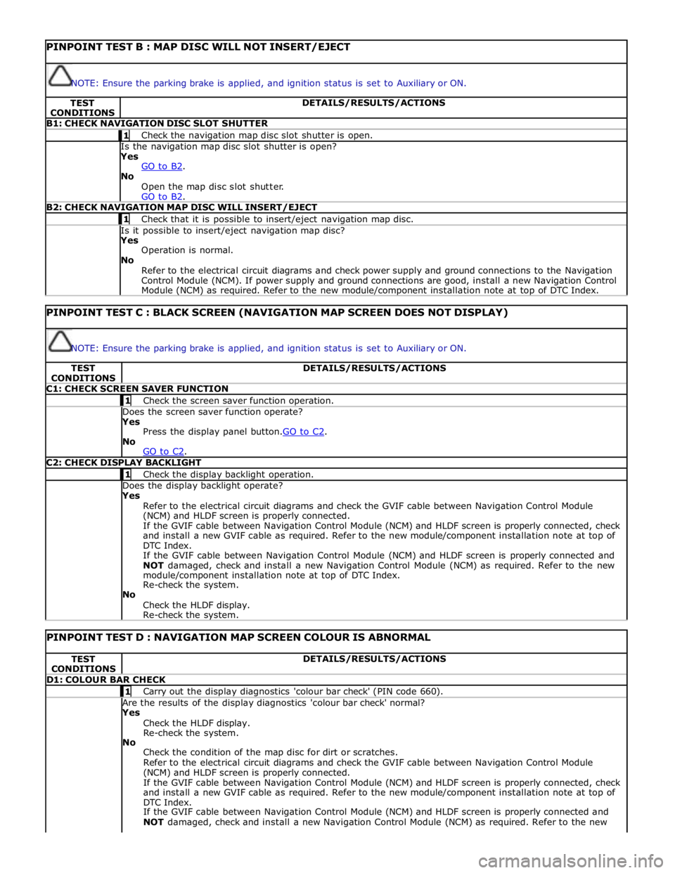
PINPOINT TEST B : MAP DISC WILL NOT INSERT/EJECT
NOTE: Ensure the parking brake is applied, and ignition status is set to Auxiliary or ON. TEST
CONDITIONS DETAILS/RESULTS/ACTIONS B1: CHECK NAVIGATION DISC SLOT SHUTTER 1 Check the navigation map disc slot shutter is open. Is the navigation map disc slot shutter is open? Yes
GO to B2. No
Open the map disc slot shutter.
GO to B2. B2: CHECK NAVIGATION MAP DISC WILL INSERT/EJECT 1 Check that it is possible to insert/eject navigation map disc. Is it possible to insert/eject navigation map disc? Yes
Operation is normal.
No
Refer to the electrical circuit diagrams and check power supply and ground connections to the Navigation
Control Module (NCM). If power supply and ground connections are good, install a new Navigation Control
Module (NCM) as required. Refer to the new module/component installation note at top of DTC Index.
PINPOINT TEST C : BLACK SCREEN (NAVIGATION MAP SCREEN DOES NOT DISPLAY)
NOTE: Ensure the parking brake is applied, and ignition status is set to Auxiliary or ON. TEST
CONDITIONS DETAILS/RESULTS/ACTIONS C1: CHECK SCREEN SAVER FUNCTION 1 Check the screen saver function operation. Does the screen saver function operate? Yes
Press the display panel button.GO to C2. No
GO to C2. C2: CHECK DISPLAY BACKLIGHT 1 Check the display backlight operation. Does the display backlight operate? Yes
Refer to the electrical circuit diagrams and check the GVIF cable between Navigation Control Module
(NCM) and HLDF screen is properly connected.
If the GVIF cable between Navigation Control Module (NCM) and HLDF screen is properly connected, check
and install a new GVIF cable as required. Refer to the new module/component installation note at top of
DTC Index.
If the GVIF cable between Navigation Control Module (NCM) and HLDF screen is properly connected and
NOT damaged, check and install a new Navigation Control Module (NCM) as required. Refer to the new
module/component installation note at top of DTC Index.
Re-check the system.
No
Check the HLDF display.
Re-check the system.
PINPOINT TEST D : NAVIGATION MAP SCREEN COLOUR IS ABNORMAL TEST
CONDITIONS DETAILS/RESULTS/ACTIONS D1: COLOUR BAR CHECK 1 Carry out the display diagnostics 'colour bar check' (PIN code 660). Are the results of the display diagnostics 'colour bar check' normal? Yes
Check the HLDF display.
Re-check the system.
No
Check the condition of the map disc for dirt or scratches.
Refer to the electrical circuit diagrams and check the GVIF cable between Navigation Control Module
(NCM) and HLDF screen is properly connected.
If the GVIF cable between Navigation Control Module (NCM) and HLDF screen is properly connected, check
and install a new GVIF cable as required. Refer to the new module/component installation note at top of
DTC Index.
If the GVIF cable between Navigation Control Module (NCM) and HLDF screen is properly connected and
NOT damaged, check and install a new Navigation Control Module (NCM) as required. Refer to the new
Page 2162 of 3039
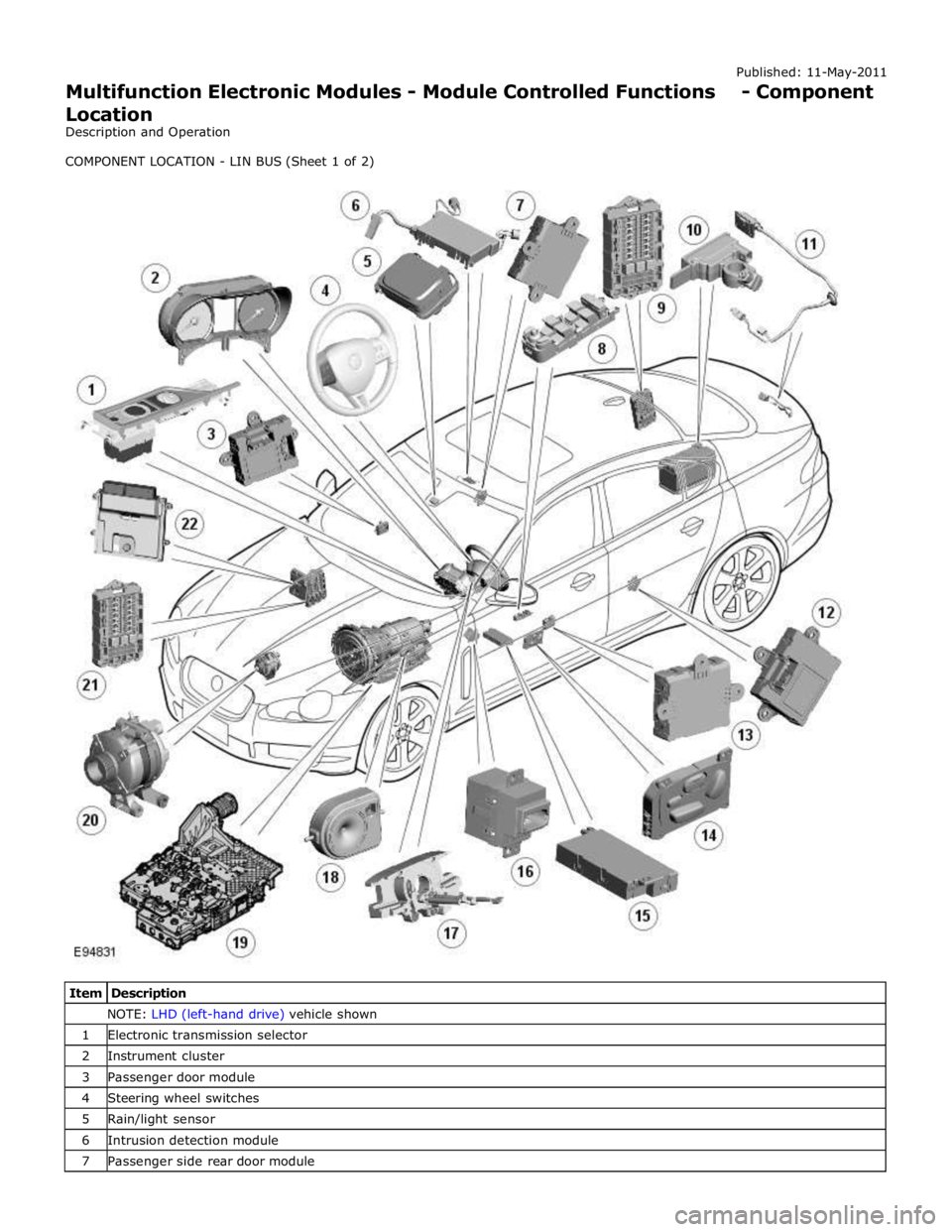
NOTE: LHD (left-hand drive) vehicle shown 1 Electronic transmission selector 2 Instrument cluster 3 Passenger door module 4 Steering wheel switches 5 Rain/light sensor 6 Intrusion detection module 7 Passenger side rear door module
Page 2172 of 3039
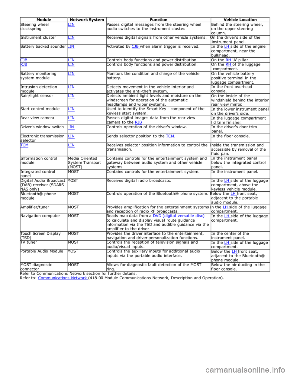
Module Network System Function Vehicle Location
Steering wheel
clockspring LIN Passes digital messages from the steering wheel
audio switches to the instrument cluster. Behind the steering wheel,
on the upper steering
column.
Instrument cluster LIN Receives digital signals from other vehicle systems. On the driver's side of the
instrument panel.
Battery backed sounder LIN Activated by CJB when alarm trigger is received. In the LH side of the engine compartment, near the
bulkhead.
CJB LIN Controls body functions and power distribution. On the RH 'A' pillar.
RJB LIN Controls body functions and power distribution. On the RH of the luggage compartment.
Battery monitoring
system module
Intrusion detection
module LIN Monitors the condition and charge of the vehicle
battery.
LIN Detects movement in the vehicle interior and
activates the anti-theft system. On the vehicle battery
positive terminal in the
luggage compartment.
In the front overhead
console.
Rain/light sensor LIN Detects ambient light levels and moisture on the
windscreen for operation of the automatic
headlamps and wiper systems.
Start control module LIN Used to identify the Smart Key - component of the
keyless start system.
Rear view camera LIN Passes digital images data from the rear view
camera to the RJB On the inside of the
windshield behind the interior
rear view mirror.
In the lower instrument panel
on the driver's side.
In the luggage compartment
lid trim finisher.
Driver's window switch LIN Controls operation of the driver's window. In the driver's door trim
panel.
Electronic transmission
selector LIN Sends selector position to the TCM. In the floor console. TCM LIN Receives selector position information to control the Inside the transmission and
Information control
module
Media Oriented
System Transport
(MOST) transmission.
Contains controls for the entertainment system and
gateway between audio system and other vehicle
systems. accessible by removal of the
fluid pan.
In the instrument panel
below the integrated control
panel.
Integrated control
panel MOST Contains controls for the entertainment system. In the instrument panel.
Digital Audio Broadcast MOST Receives digital radio broadcasts. In the LH side of the luggage (DAB) receiver (SDARS
NAS only)
Bluetooth® phone
module compartment, above the
keyless vehicle module.
MOST Controls operation of the Bluetooth® phone system. Below the LH front seat, adjacent to the portable
audio module.
Amplifier/tuner MOST Provides amplification for the entertainment systems In the LH side of the luggage and reception of radio RF broadcasts.
Navigation computer MOST Reads map data from a DVD (digital versatile disc)
to calculate and display visual route guidance
information via the TSD and audible guidance via the
amplifier to the driver. compartment.
In the LH side of the luggage compartment.
Touch Screen Display
(TSD) MOST Provides the driver interface to the entertainment,
navigation and driver personalization functions. In the center of the
instrument panel.
TV tuner MOST Controls the reception of television signals and
audio/visual inputs.
Portable Audio Module MOST Controls the auxiliary inputs for additional audio
inputs via the portable audio interface. In the LH side of the luggage compartment.
Below the LH front seat, adjacent to the Bluetooth®
phone module.
MOST diagnostic
connector MOST Allows for diagnostic fault detection of the MOST
ring. Below the air ducting in the
floor console.
Refer to Communications Network section for further details.
Refer to: Communications Network (418-00 Module Communications Network, Description and Operation).
Page 2219 of 3039
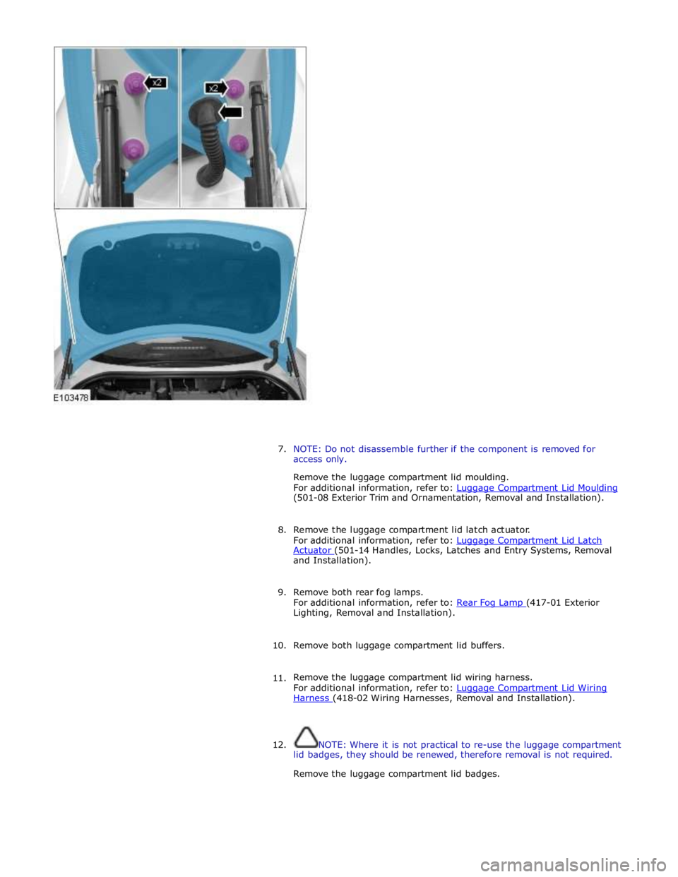
7. NOTE: Do not disassemble further if the component is removed for
access only.
Remove the luggage compartment lid moulding.
For additional information, refer to: Luggage Compartment Lid Moulding (501-08 Exterior Trim and Ornamentation, Removal and Installation).
8. Remove the luggage compartment lid latch actuator.
For additional information, refer to: Luggage Compartment Lid Latch Actuator (501-14 Handles, Locks, Latches and Entry Systems, Removal and Installation).
9. Remove both rear fog lamps.
For additional information, refer to: Rear Fog Lamp (417-01 Exterior Lighting, Removal and Installation).
10. Remove both luggage compartment lid buffers.
11. Remove the luggage compartment lid wiring harness.
For additional information, refer to: Luggage Compartment Lid Wiring Harness (418-02 Wiring Harnesses, Removal and Installation).
12. NOTE: Where it is not practical to re-use the luggage compartment
lid badges, they should be renewed, therefore removal is not required.
Remove the luggage compartment lid badges.
Page 2292 of 3039
Rear View Mirrors - Rear View Mirrors - Overview
Description and Operation
Overview
The exterior mirrors incorporate the following:
Blind spot monitoring indicator
Auto dimming function
Turn signal indicators
Approach lamps
Exterior temperature sensor
Heated mirror function
Reverse dipping function Published: 11-May-2011
Movement of the door mirrors is controlled from a switch pack located on the drivers door. The switch pack contains 2
non-latching mirror select buttons labeled 'L' and 'R' and a 4-way mirror movement switch. Door mirror movement commands
are transmitted to the driver's door module over the LIN (local interconnect network) bus. The drivers door module transmits
any mirror movement commands to the passenger door module over the medium speed CAN (controller area network) bus.
Movement of the door mirrors is carried out by the respective door module. The door modules provide supply and ground paths
to the mirror motors and monitor mirror position via potentiometers located in the mirror housings.
Both exterior door mirrors and the interior mirror feature an auto dimming function. The interior rear view mirror contains one
forward and one reward facing light sensor. The light sensors control the auto dimming feature of the interior mirror to reduce
glare from the headlights of following vehicles.
When auto-dimming of the interior mirror is required, a supply is provided by the interior mirror to both door mirrors to initiate
the door mirror auto-dimming sequence.
Blind spot monitoring function alerts the driver to a vehicle located in the vehicle blind spot. A warning indicator is located in
each exterior mirror towards the outer edge.
Refer to: Blindspot Monitoring System (413-09 Warning Devices, Description and Operation).