2010 JAGUAR XFR light
[x] Cancel search: lightPage 2066 of 3039
Published: 11-May-2011
Daytime Running Lamps (DRL) - Daytime Running Lamps (DRL) - System
Operation and Component Description
Description and Operation
CENTRAL JUNCTION BOX (CJB) System Operation
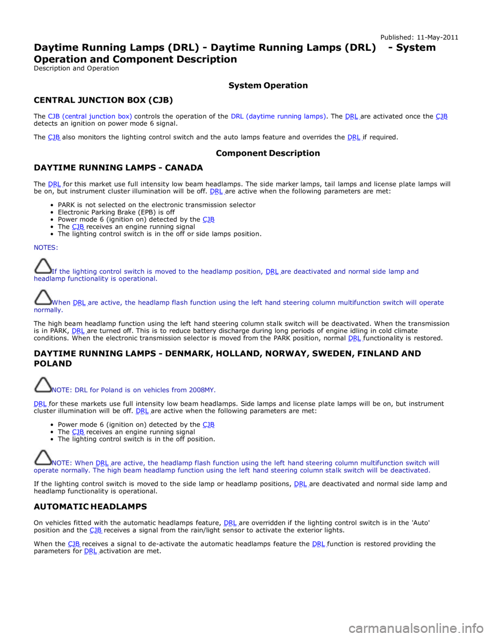
The CJB (central junction box) controls the operation of the DRL (daytime running lamps). The DRL are activated once the CJB detects an ignition on power mode 6 signal.
The CJB also monitors the lighting control switch and the auto lamps feature and overrides the DRL if required.
DAYTIME RUNNING LAMPS - CANADA Component Description
The DRL for this market use full intensity low beam headlamps. The side marker lamps, tail lamps and license plate lamps will be on, but instrument cluster illumination will be off. DRL are active when the following parameters are met:
PARK is not selected on the electronic transmission selector
Electronic Parking Brake (EPB) is off
Power mode 6 (ignition on) detected by the CJB The CJB receives an engine running signal The lighting control switch is in the off or side lamps position.
NOTES:
If the lighting control switch is moved to the headlamp position, DRL are deactivated and normal side lamp and headlamp functionality is operational.
When DRL are active, the headlamp flash function using the left hand steering column multifunction switch will operate normally.
The high beam headlamp function using the left hand steering column stalk switch will be deactivated. When the transmission
is in PARK, DRL are turned off. This is to reduce battery discharge during long periods of engine idling in cold climate conditions. When the electronic transmission selector is moved from the PARK position, normal DRL functionality is restored.
DAYTIME RUNNING LAMPS - DENMARK, HOLLAND, NORWAY, SWEDEN, FINLAND AND POLAND
NOTE: DRL for Poland is on vehicles from 2008MY.
DRL for these markets use full intensity low beam headlamps. Side lamps and license plate lamps will be on, but instrument cluster illumination will be off. DRL are active when the following parameters are met:
Power mode 6 (ignition on) detected by the CJB The CJB receives an engine running signal The lighting control switch is in the off position.
NOTE: When DRL are active, the headlamp flash function using the left hand steering column multifunction switch will operate normally. The high beam headlamp function using the left hand steering column stalk switch will be deactivated.
If the lighting control switch is moved to the side lamp or headlamp positions, DRL are deactivated and normal side lamp and headlamp functionality is operational.
AUTOMATIC HEADLAMPS
On vehicles fitted with the automatic headlamps feature, DRL are overridden if the lighting control switch is in the 'Auto' position and the CJB receives a signal from the rain/light sensor to activate the exterior lights.
When the CJB receives a signal to de-activate the automatic headlamps feature the DRL function is restored providing the parameters for DRL activation are met.
Page 2078 of 3039
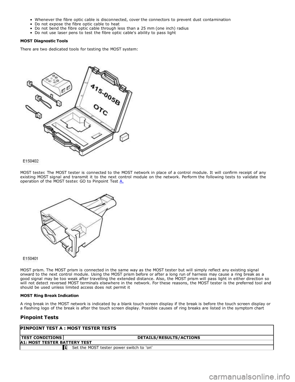
MOST prism. The MOST prism is connected in the same way as the MOST tester but will simply reflect any existing signal
onward to the next control module. Using the MOST prism before or after a long run of harness may cause a ring break as a
good signal may be too weak after travelling the extended distance. Also, the MOST prism will pass light in either direction so
will not detect reversed MOST terminals elsewhere in the network. For these reasons, the MOST tester is the preferred tool and
should be used unless limited access does not permit it
MOST Ring Break Indication
A ring break in the MOST network is indicated by a blank touch screen display if the break is before the touch screen display or
a flashing logo of the break is after the touch screen display. Possible causes of ring breaks are listed in the symptom chart
Pinpoint Tests
PINPOINT TEST A : MOST TESTER TESTS TEST CONDITIONS DETAILS/RESULTS/ACTIONS A1: MOST TESTER BATTERY TEST 1 Set the MOST tester power switch to 'on'
Page 2080 of 3039
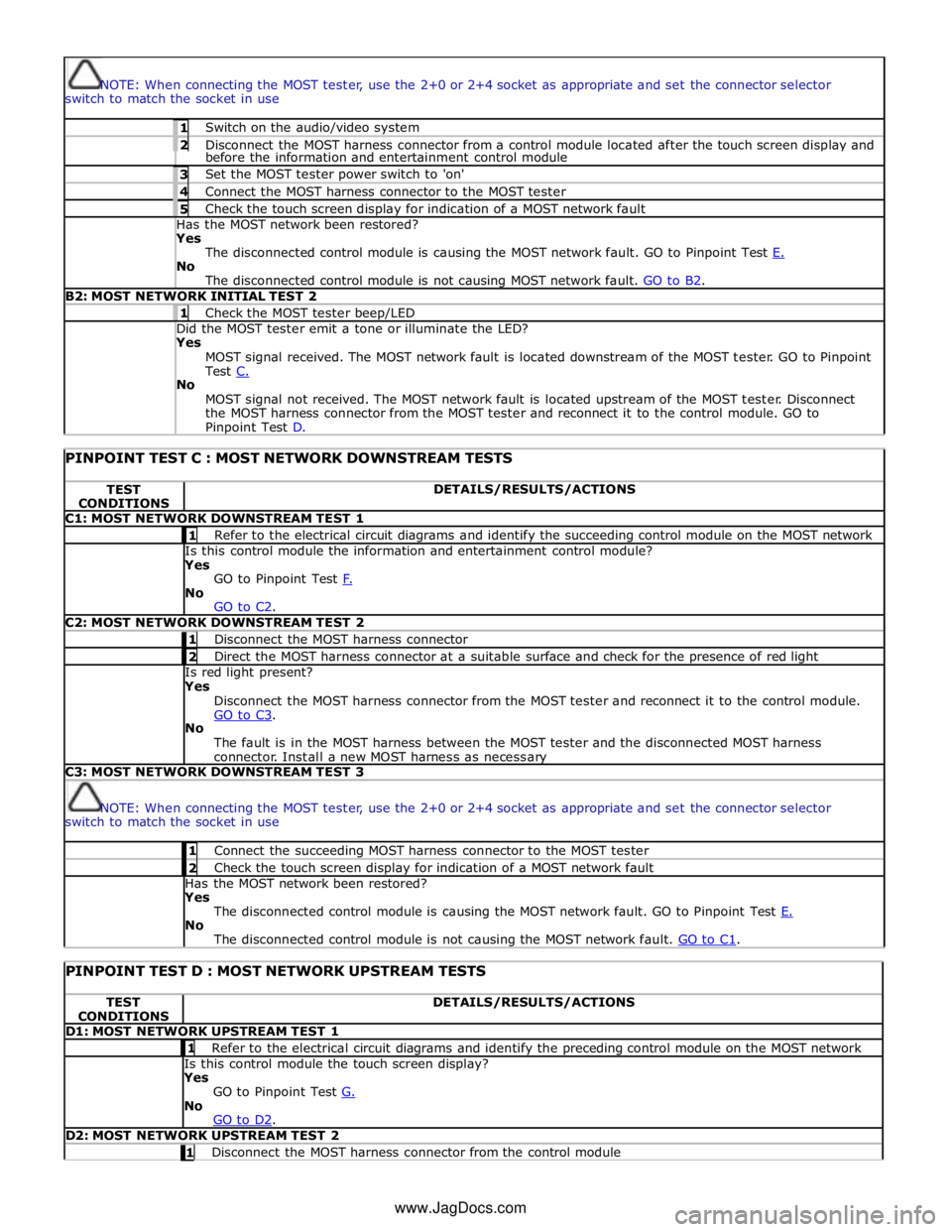
NOTE: When connecting the MOST tester, use the 2+0 or 2+4 socket as appropriate and set the connector selector
switch to match the socket in use 1 Switch on the audio/video system 2 Disconnect the MOST harness connector from a control module located after the touch screen display and before the information and entertainment control module 3 Set the MOST tester power switch to 'on' 4 Connect the MOST harness connector to the MOST tester 5 Check the touch screen display for indication of a MOST network fault Has the MOST network been restored? Yes
The disconnected control module is causing the MOST network fault. GO to Pinpoint Test E. No
The disconnected control module is not causing MOST network fault. GO to B2. B2: MOST NETWORK INITIAL TEST 2 1 Check the MOST tester beep/LED Did the MOST tester emit a tone or illuminate the LED? Yes
MOST signal received. The MOST network fault is located downstream of the MOST tester. GO to Pinpoint
Test C. No
MOST signal not received. The MOST network fault is located upstream of the MOST tester. Disconnect
the MOST harness connector from the MOST tester and reconnect it to the control module. GO to Pinpoint Test D.
PINPOINT TEST C : MOST NETWORK DOWNSTREAM TESTS TEST
CONDITIONS DETAILS/RESULTS/ACTIONS C1: MOST NETWORK DOWNSTREAM TEST 1 1 Refer to the electrical circuit diagrams and identify the succeeding control module on the MOST network Is this control module the information and entertainment control module?
Yes
GO to Pinpoint Test F. No
GO to C2. C2: MOST NETWORK DOWNSTREAM TEST 2 1 Disconnect the MOST harness connector 2 Direct the MOST harness connector at a suitable surface and check for the presence of red light Is red light present?
Yes
Disconnect the MOST harness connector from the MOST tester and reconnect it to the control module.
GO to C3. No
The fault is in the MOST harness between the MOST tester and the disconnected MOST harness
connector. Install a new MOST harness as necessary C3: MOST NETWORK DOWNSTREAM TEST 3
NOTE: When connecting the MOST tester, use the 2+0 or 2+4 socket as appropriate and set the connector selector
switch to match the socket in use 1 Connect the succeeding MOST harness connector to the MOST tester 2 Check the touch screen display for indication of a MOST network fault Has the MOST network been restored?
Yes
The disconnected control module is causing the MOST network fault. GO to Pinpoint Test E. No
The disconnected control module is not causing the MOST network fault. GO to C1.
PINPOINT TEST D : MOST NETWORK UPSTREAM TESTS TEST
CONDITIONS DETAILS/RESULTS/ACTIONS D1: MOST NETWORK UPSTREAM TEST 1 1 Refer to the electrical circuit diagrams and identify the preceding control module on the MOST network Is this control module the touch screen display?
Yes
GO to Pinpoint Test G. No
GO to D2. D2: MOST NETWORK UPSTREAM TEST 2 1 Disconnect the MOST harness connector from the control module www.JagDocs.com
Page 2081 of 3039
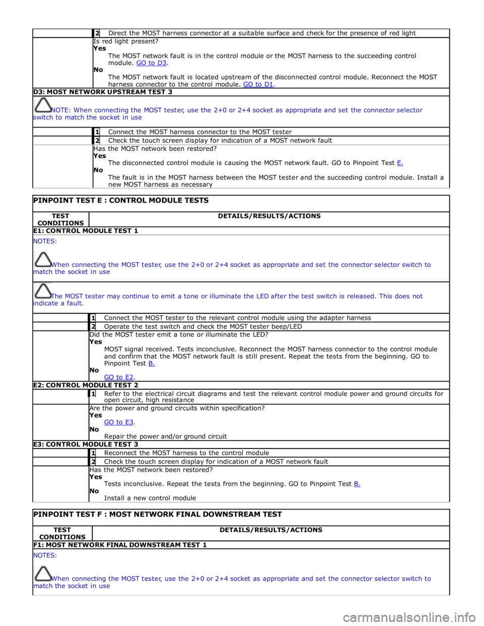
2 Direct the MOST harness connector at a suitable surface and check for the presence of red light Is red light present?
Yes
The MOST network fault is in the control module or the MOST harness to the succeeding control
module. GO to D3. No
The MOST network fault is located upstream of the disconnected control module. Reconnect the MOST
harness connector to the control module. GO to D1. D3: MOST NETWORK UPSTREAM TEST 3
NOTE: When connecting the MOST tester, use the 2+0 or 2+4 socket as appropriate and set the connector selector
switch to match the socket in use 1 Connect the MOST harness connector to the MOST tester 2 Check the touch screen display for indication of a MOST network fault Has the MOST network been restored?
Yes
The disconnected control module is causing the MOST network fault. GO to Pinpoint Test E. No
The fault is in the MOST harness between the MOST tester and the succeeding control module. Install a
new MOST harness as necessary
PINPOINT TEST E : CONTROL MODULE TESTS TEST
CONDITIONS DETAILS/RESULTS/ACTIONS E1: CONTROL MODULE TEST 1 NOTES:
When connecting the MOST tester, use the 2+0 or 2+4 socket as appropriate and set the connector selector switch to
match the socket in use
The MOST tester may continue to emit a tone or illuminate the LED after the test switch is released. This does not
indicate a fault. 1 Connect the MOST tester to the relevant control module using the adapter harness 2 Operate the test switch and check the MOST tester beep/LED Did the MOST tester emit a tone or illuminate the LED? Yes
MOST signal received. Tests inconclusive. Reconnect the MOST harness connector to the control module
and confirm that the MOST network fault is still present. Repeat the tests from the beginning. GO to
Pinpoint Test B. No
GO to E2. E2: CONTROL MODULE TEST 2 1 Refer to the electrical circuit diagrams and test the relevant control module power and ground circuits for open circuit, high resistance Are the power and ground circuits within specification? Yes
GO to E3. No
Repair the power and/or ground circuit E3: CONTROL MODULE TEST 3 1 Reconnect the MOST harness to the control module 2 Check the touch screen display for indication of a MOST network fault Has the MOST network been restored? Yes
Tests inconclusive. Repeat the tests from the beginning. GO to Pinpoint Test B. No
Install a new control module
PINPOINT TEST F : MOST NETWORK FINAL DOWNSTREAM TEST TEST
CONDITIONS DETAILS/RESULTS/ACTIONS F1: MOST NETWORK FINAL DOWNSTREAM TEST 1 NOTES:
When connecting the MOST tester, use the 2+0 or 2+4 socket as appropriate and set the connector selector switch to
match the socket in use
Page 2083 of 3039
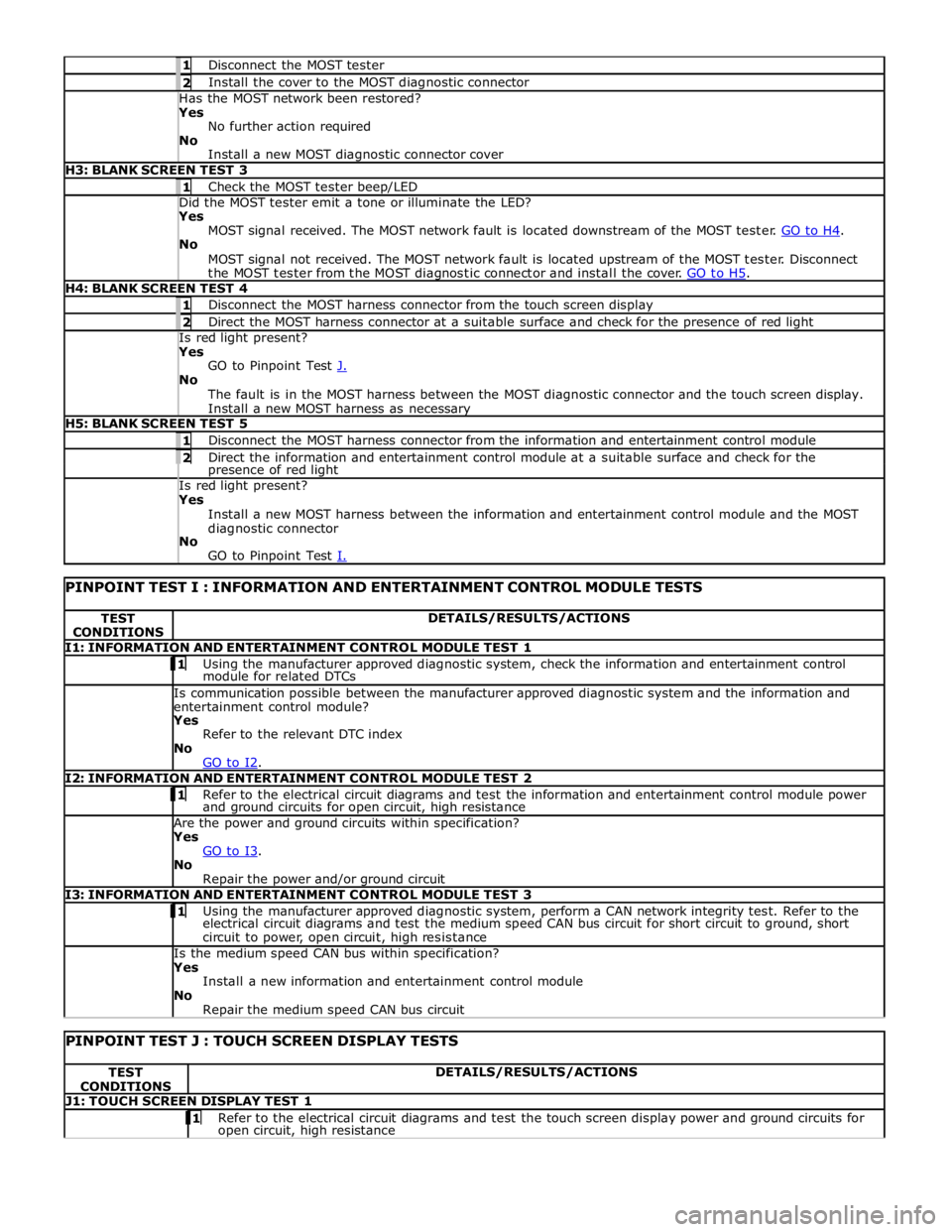
1 Disconnect the MOST tester 2 Install the cover to the MOST diagnostic connector Has the MOST network been restored? Yes
No further action required
No
Install a new MOST diagnostic connector cover H3: BLANK SCREEN TEST 3 1 Check the MOST tester beep/LED Did the MOST tester emit a tone or illuminate the LED? Yes
MOST signal received. The MOST network fault is located downstream of the MOST tester. GO to H4. No
MOST signal not received. The MOST network fault is located upstream of the MOST tester. Disconnect
the MOST tester from the MOST diagnostic connector and install the cover. GO to H5. H4: BLANK SCREEN TEST 4 1 Disconnect the MOST harness connector from the touch screen display 2 Direct the MOST harness connector at a suitable surface and check for the presence of red light Is red light present? Yes
GO to Pinpoint Test J. No
The fault is in the MOST harness between the MOST diagnostic connector and the touch screen display.
Install a new MOST harness as necessary H5: BLANK SCREEN TEST 5 1 Disconnect the MOST harness connector from the information and entertainment control module 2 Direct the information and entertainment control module at a suitable surface and check for the presence of red light Is red light present? Yes
Install a new MOST harness between the information and entertainment control module and the MOST
diagnostic connector
No
GO to Pinpoint Test I.
PINPOINT TEST I : INFORMATION AND ENTERTAINMENT CONTROL MODULE TESTS TEST
CONDITIONS DETAILS/RESULTS/ACTIONS I1: INFORMATION AND ENTERTAINMENT CONTROL MODULE TEST 1 1 Using the manufacturer approved diagnostic system, check the information and entertainment control module for related DTCs Is communication possible between the manufacturer approved diagnostic system and the information and
entertainment control module? Yes
Refer to the relevant DTC index
No
GO to I2. I2: INFORMATION AND ENTERTAINMENT CONTROL MODULE TEST 2 1 Refer to the electrical circuit diagrams and test the information and entertainment control module power and ground circuits for open circuit, high resistance Are the power and ground circuits within specification? Yes
GO to I3. No
Repair the power and/or ground circuit I3: INFORMATION AND ENTERTAINMENT CONTROL MODULE TEST 3 1 Using the manufacturer approved diagnostic system, perform a CAN network integrity test. Refer to the electrical circuit diagrams and test the medium speed CAN bus circuit for short circuit to ground, short
circuit to power, open circuit, high resistance Is the medium speed CAN bus within specification? Yes
Install a new information and entertainment control module
No
Repair the medium speed CAN bus circuit
PINPOINT TEST J : TOUCH SCREEN DISPLAY TESTS TEST
CONDITIONS DETAILS/RESULTS/ACTIONS J1: TOUCH SCREEN DISPLAY TEST 1 1 Refer to the electrical circuit diagrams and test the touch screen display power and ground circuits for open circuit, high resistance
Page 2085 of 3039

DTC Description Possible Cause Action B100951
Ignition
Authorisation
Faulty instrument cluster
Target SID re-synchronisation
error following programming
CAN fault Check ignition, power and ground supplies to CJB and
instrument cluster. Re-synchronize ID by re-configuring
the instrument cluster as a new module. Check CAN
communications between instrument cluster and tester B100962
Ignition
Authorisation
Low speed CAN fault
CJB fault
Instrument cluster fault
Incorrect module installed
(CJB/Instrument cluster)
Target SID synchronisation
error following re-programming
Noise/EMC related error Check CAN communications between CJB and instrument
cluster. Check ignition, power and ground supplies to CJB
and instrument cluster. Confirm correct module is
installed. Re-synchronise ID by re-configuring the
instrument cluster as a new module. Check CAN network
for interference/EMC related issues B100963
Ignition
Authorisation
CJB fault
Low speed CAN fault
Instrument cluster fault
Low battery voltage <9V Check Power and Ground supplies to CJB and instrument
cluster. Check CAN communications between CJB and
instrument cluster. Check battery is in fully charged and
serviceable condition, refer to the battery care manual B100964
Ignition
Authorisation
CJB fault
Low speed CAN fault
Instrument cluster fault Check power and ground supplies to CJB and instrument
cluster. Check CAN communications between CJB and
instrument cluster B102B67 Passive Key
CJB fault
Low speed CAN fault
Remote Keyless Entry (RKE)
module fault
Write target SID
synchronisation error following
re-programming Check power and ground supplies to CJB and RKE
module. Check CAN communications between CJB and
RKE module. Re-synchronise ID by re-configuring the RKE
module as a new module B102B87 Passive Key
CJB fault
Low speed CAN fault
RKE module fault
Key fob battery low/battery
contact issue
Interference from other RF
signal
EMC/noise
Receiver fault
Receiver not programmed
correctly
Serial communications fault
(between receiver and RKE
module)
Key fault
Passive antenna fault
Confirm placement of key
within vehicle Check power and ground supplies to CJB, RKE module
and receiver. Check CAN communications between CJB
and instrument cluster. Check key fob battery. Confirm
vehicle surroundings, move vehicle. Check CAN network
for interference/EMC related issues. Disconnect battery,
then re-connect - confirm operation by re-programming
keys. Check serial circuit between receiver and RKE
module. Confirm spare key works. Refer to the electrical
circuit diagrams and test circuits to all 3 antennas. Check
whereabouts of key B108413
Boot/Trunk Motor
Close Switch
Trunk latch open signal circuit -
open circuit Refer to the electrical circuit diagrams and check trunk
latch open signal circuit for open circuit B108783 LIN Bus "A"
Checksum of the received LIN
frame from battery backed
sounder, roof header console,
and/or rain/light sensor is
incorrect Check operation of rain/light sensor by covering sensor or
applying water to screen, install a new sensor as
required B108788 LIN Bus "A"
Bus off. Battery backed
sounder, roof header console,
and/or rain/light sensor LIN
circuit - short to ground, power Carry out any pinpoint tests associated with this DTC
using the manufacturer approved diagnostic system.
Refer to the electrical circuit diagrams and check battery
backed sounder, roof header console, and rain/light
sensor LIN circuit for short to ground, power B108A11 Start Button
Start/Stop switch analogue
input circuits 1 or 2 - short to
ground Refer to the electrical circuit diagrams and check
Start/Stop switch analogue input circuits 1 and 2 for
short to ground www.JagDocs.com
Page 2086 of 3039

DTC Description Possible Cause Action B108A12 Start Button
Start/Stop switch analogue
input circuits 1 or 2 - short to
power Refer to the electrical circuit diagrams and check
Start/Stop switch analogue input circuits 1 and 2 for
short to power B109512 Wiper On/Off Relay
Wiper On/Off relay control
circuit - short to power Carry out any pinpoint tests associated with this DTC
using the manufacturer approved diagnostic system.
Refer to the electrical circuit diagrams and check wiper
On/Off relay control circuit for short to power B109514 Wiper On/Off Relay
Wiper On/Off relay control
circuit - short to ground, open
circuit Refer to the electrical circuit diagrams and check wiper
On/Off relay control circuit for short to ground, open
circuit B109612
Wiper High/Low
Relay
Wiper Fast/Slow relay control
circuit - short to power Carry out any pinpoint tests associated with this DTC
using the manufacturer approved diagnostic system.
Refer to the electrical circuit diagrams and check wiper
Fast/Slow relay control circuit for short to power B109614
Wiper High/Low
Relay
Wiper Fast/Slow relay control
circuit - short to ground, open
circuit Refer to the electrical circuit diagrams and check wiper
Fast/Slow relay control circuit for short to ground, open
circuit B109712
Heated Windshield
Relay
Heated windshield relay control
circuit - short to power Carry out any pinpoint tests associated with this DTC
using the manufacturer approved diagnostic system.
Refer to the electrical circuit diagrams and check heated
windshield relay control circuit for short to power B109714
Heated Windshield
Relay
Heated windshield relay control
circuit - short to ground, open
circuit Refer to the electrical circuit diagrams and check heated
windshield relay control circuit for short to ground, open
circuit B10A612 Main Light Switch
Master light switch signal from
roof header console circuit -
short to power Refer to the electrical circuit diagrams and check master
light switch signal from roof header console circuit for
short to power B10A623 Main Light Switch
Master light switch signal from
roof header console signal
stuck low. Switch is read as ON
for too long a time Carry out any pinpoint tests associated with this DTC
using the manufacturer approved diagnostic system.
Refer to the electrical circuit diagrams and check master
light switch signal from roof header console for short to
ground B10AD09 Rain Sensor
Component failures Carry out any pinpoint tests associated with this DTC
using the manufacturer approved diagnostic system.
Suspect the rain/light sensor, check and install a new
sensor as required B10AD11 Rain Sensor
Rain/light sensor power circuit -
short to ground Carry out any pinpoint tests associated with this DTC
using the manufacturer approved diagnostic system.
Refer to the electrical circuit diagrams and check rain/light sensor power circuit for short to ground B10AD96 Rain Sensor
Component internal failure Suspect the rain/light sensor, check and install a new
sensor as required B10E511
PCM Wake-up
Signal
ECM wake-up signal circuit -
short to ground Refer to the electrical circuit diagrams and check ECM
wake-up signal circuit for short to ground B10E512
PCM Wake-up
Signal
ECM wake-up signal circuit -
short to power Refer to the electrical circuit diagrams and check ECM
wake-up signal circuit for short to power B10E513
PCM Wake-up
Signal
ECM wake-up signal circuit -
open circuit Refer to the electrical circuit diagrams and check ECM
wake-up signal circuit for open circuit B10F111 Key In Switch
Keyless vehicle module, key IN
status circuit - short to ground Carry out any pinpoint tests associated with this DTC
using the manufacturer approved diagnostic system.
Refer to the electrical circuit diagrams and check keyless
vehicle module, key IN status circuit for short to ground B10F112 Key In Switch
Keyless vehicle module, key IN
status circuit - short to power Refer to the electrical circuit diagrams and check keyless
vehicle module, key IN status circuit for short to power B10F113 Key In Switch
Keyless vehicle module, key IN
status circuit - open circuit Refer to the electrical circuit diagrams and check keyless
vehicle module, key IN status circuit for open circuit
Page 2087 of 3039

DTC Description Possible Cause Action B10F211 Sunroof Control
Sunroof enable signal circuit -
short to ground Carry out any pinpoint tests associated with this DTC
using the manufacturer approved diagnostic system.
Refer to the electrical circuit diagrams and check sunroof
enable signal circuit for short to ground B10F212 Sunroof Control
Sunroof enable signal circuit -
short to power Refer to the electrical circuit diagrams and check sunroof
enable signal circuit for short to power B10F213 Sunroof Control
Sunroof enable signal circuit -
open circuit Refer to the electrical circuit diagrams and check sunroof
enable signal circuit for open circuit B10F311
Left Front Position
Light
Left front side lamps circuit -
short to ground Carry out any pinpoint tests associated with this DTC
using the manufacturer approved diagnostic system.
Refer to the electrical circuit diagrams and check left
front side lamps circuit for short to ground B10F315
Left Front Position
Light
Left front side lamps circuit -
short to power, open circuit Carry out any pinpoint tests associated with this DTC
using the manufacturer approved diagnostic system.
Refer to the electrical circuit diagrams and check left
front side lamps circuit for short to power, open circuit B10F411
Right Front Position
Light
Right front side lamps circuit -
short to ground Carry out any pinpoint tests associated with this DTC
using the manufacturer approved diagnostic system.
Refer to the electrical circuit diagrams and check right
front side lamps circuit for short to ground B10F415
Right Front Position
Light
Right front side lamps circuit -
short to power, open circuit Carry out any pinpoint tests associated with this DTC
using the manufacturer approved diagnostic system.
Refer to the electrical circuit diagrams and check right
front side lamps circuit for short to power, open circuit B10F812
Accessory socket 'A'
relay
Accessory socket 'A' relay
control circuit - short to power Carry out any pinpoint tests associated with this DTC
using the manufacturer approved diagnostic system.
Refer to the electrical circuit diagrams and check
accessory socket 'A' relay control circuit for short to power B10F814
Accessory socket 'A'
relay
Accessory socket 'A' relay
control circuit - short to ground,
open circuit Refer to the electrical circuit diagrams and check
accessory socket 'A' relay control circuit for short to
ground, open circuit B10F912
Accessory socket 'B'
relay
Front powerpoint, trailer tow
connector, road pricing
connector, sunblind power
supply circuits - short to power Refer to the electrical circuit diagrams and check front
powerpoint, trailer tow connector, road pricing connector,
sunblind power supply circuits for short to power B10F914
Accessory socket 'B'
relay
Front powerpoint, trailer tow
connector, road pricing
connector, sunblind power
supply circuits - short to
ground, open circuit Refer to the electrical circuit diagrams and check front
powerpoint, trailer tow connector, road pricing connector,
sunblind power supply circuits for short to ground, open
circuit B10F993
Accessory socket 'B'
relay
Front powerpoint, trailer tow
connector, road pricing
connector, sunblind power
supply circuits - short to power,
ground, open circuit Carry out any pinpoint tests associated with this DTC
using the manufacturer approved diagnostic system.
Refer to the electrical circuit diagrams and check front
powerpoint, trailer tow connector, road pricing connector,
sunblind power supply circuits for short to power, ground,
open circuit B10FA93
Delayed Power Off
relay
ADRC ECM, roof header console
lamp, glove box lamp , RH/LH
footwell lamps, JAG Sense
glove box module, RH/LH
sunvisor lamps, rear dome
lamps switched power circuits -
short to power, open circuit Carry out any pinpoint tests associated with this DTC
using the manufacturer approved diagnostic system.
Refer to the electrical circuit diagrams and check ADRC
ECM, roof header console lamp, glove box lamp , RH/LH
footwell lamps, JAG Sense glove box module, RH/LH
sunvisor lamps, rear dome lamps switched power circuits
for short to power, open circuit B10FF11 Ignition control
ECM and FPDB ignition control
circuit - short to ground Carry out any pinpoint tests associated with this DTC
using the manufacturer approved diagnostic system.
Refer to the electrical circuit diagrams and check ECM and
FPDB ignition control circuit for short to ground B10FF13 Ignition control
ECM and FPDB ignition control
circuit - open circuit Carry out any pinpoint tests associated with this DTC
using the manufacturer approved diagnostic system.
Refer to the electrical circuit diagrams and check ECM and
FPDB ignition control circuit for open circuit