2010 JAGUAR XFR check engine
[x] Cancel search: check enginePage 1448 of 3039

DTC Description Possible Cause Action U0416-68
Invalid Data Received From
Vehicle Dynamics Control
Module - event information
Event information brake
information Check Engine control module for stored DTCs. Check
CAN Bus Circuit for fault U0422-68
Invalid Data Received From
Body Control Module - event
information
Event information invalid
Power mode information Check Central junction box for stored DTCs. Check CAN
Bus Circuit for fault U101B-87
Lost Communication With
GSM - Multiple Bus-missing
message
Missing message lost
communication with
Transmission Shift
Module (multiple Bus) Check Transmission Shift Module for stored DTCs.
Refer to Circuit diagrams and check CAN and LIN Bus
for Circuit fault U3000-49
Control Module - internal
electronic failure
Internal electronic failure Suspect the Transmission control module. Install a
new Transmission control module as required, refer to
the new module/component installation note at the top of the DTC Index U3000-4B
Control Module - Circuit
resistance above threshold
Internal electronic failure Check and correct oil level. Check hydraulic flow
through oil cooler and pipe circuit for restriction or
blockage. If no restrictions found, suspect the
Transmission control module. Install a new
Transmission control module as required, refer to the
new module/component installation note at the top of
the DTC Index U3000-81
Control Module - invalid
serial data received
Vehicle or Engine type
signal incorrect from BCM
or incorrect Transmission
control module software
installed Reflash the Transmission control module using the
manufacturer approved process U3001-94
Control Module Improper
Shutdown - unexpected
operation
Control Module Improper
Shutdown (voltage
related) Check Engine control module For Power (generator)
faults. Check Power and Ground Circuit and Battery for
fault. Clear DTCs. Road Test. If DTC reoccurs suspect
the Transmission control module. Install a new
Transmission control module as required, refer to the
new module/component installation note at the top of
the DTC Index
Page 1449 of 3039
Published: 11-May-2011
Automatic Transmission/Transaxle - TDV6 3.0L Diesel /V8 5.0L Petrol/V8 S/C 5.0L Petrol - Transmission Fluid Level Check
General Procedures
WARNINGS: Activation
Observe due care when draining, as the fluid can be very hot.
Observe due care when working near a hot exhaust system.
1.
The following steps must be observed before starting the
transmission fluid level check.
The vehicle must be on a horizontal ramp.
The parking brake must be applied.
The engine must be running for 2 minutes with the transmission
control switch (TCS) in the "P" position.
2. CAUTION: Make sure that the transmission fluid temperature is
below 30 degrees before starting the fluid level check.
Connect Jaguar approved diagnostic equipment to the vehicle.
3.
Apply, and hold, the footbrake.
Move the selector lever from 'P' through all the gear positions,
pausing in each gear position for 2-3 seconds and return to the
'P' position.
4. WARNING: Make sure to support the vehicle with axle stands.
Raise and support the vehicle.
5. Refer to: Air Deflector (501-02 Front End Body Panels, Removal and Installation).
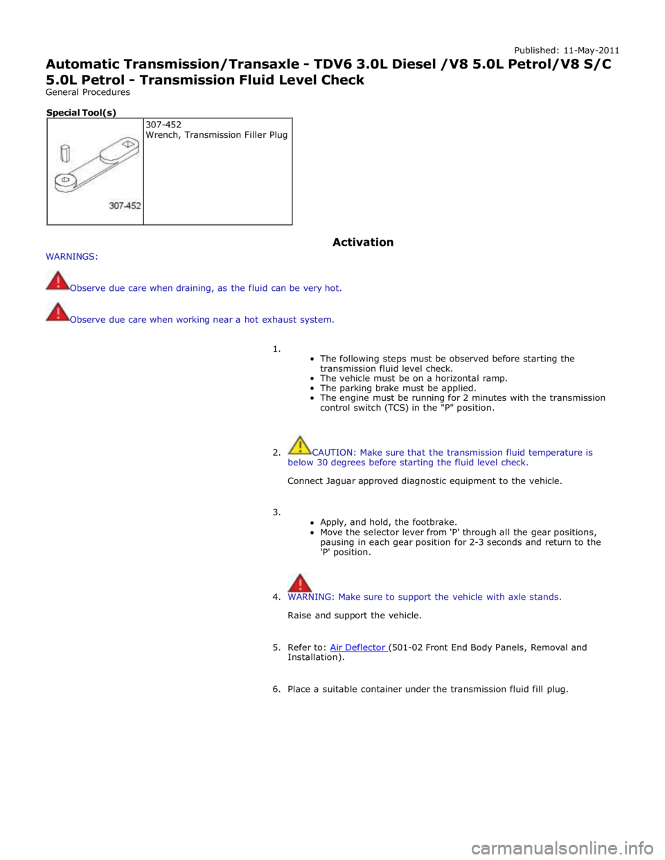
6. Place a suitable container under the transmission fluid fill plug. 307-452
Wrench, Transmission Filler Plug Special Tool(s)
Page 1486 of 3039
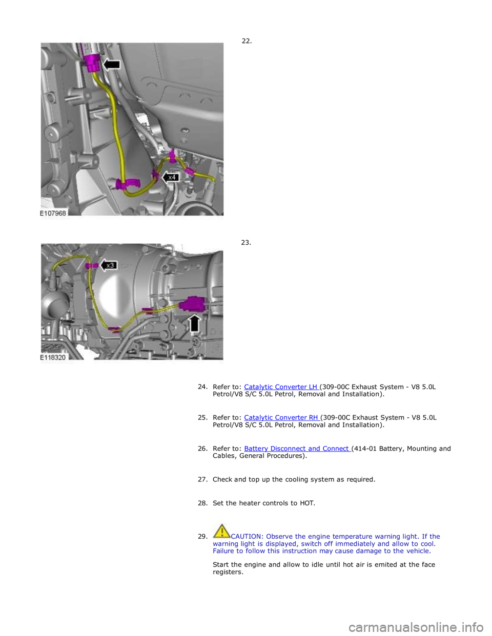
22.
23.
24.
Refer to: Catalytic Converter LH (309-00C Exhaust System - V8 5.0L Petrol/V8 S/C 5.0L Petrol, Removal and Installation).
25. Refer to: Catalytic Converter RH (309-00C Exhaust System - V8 5.0L Petrol/V8 S/C 5.0L Petrol, Removal and Installation).
26. Refer to: Battery Disconnect and Connect (414-01 Battery, Mounting and Cables, General Procedures).
27. Check and top up the cooling system as required.
28. Set the heater controls to HOT.
29. CAUTION: Observe the engine temperature warning light. If the
warning light is displayed, switch off immediately and allow to cool.
Failure to follow this instruction may cause damage to the vehicle.
Start the engine and allow to idle until hot air is emited at the face
registers.
Page 1487 of 3039
30. CAUTION: Observe the engine temperature warning light. If the
warning light is displayed, switch off immediately and allow to cool.
Failure to follow this instruction may cause damage to the vehicle.
Raise the engine speed to 2000 RPM and maintain at 2000 RPM until the
engine cooling fan operates.
31. CAUTION: Switch off the engine and allow the coolant temperature
to go cold.
Switch the engine off and allow to cool.
32. Visually check the engine and cooling system for signs of coolant
leakage.
33. WARNINGS:
When releasing the cooling system pressure, cover the coolant
expansion tank cap with a thick cloth.
Since injury such as scalding could be caused by escaping steam or
coolant, make sure the vehicle cooling system is cool prior to carrying
out this procedure.
CAUTIONS:
Make sure the coolant level remains above the "COLD FILL RANGE"
lower level mark.
Anti-freeze concentration must be maintained at 50%.
NOTE: When the cooling system is warm, the coolant will be
approximately 10mm above the upper level mark on the expansion tank
with the cap removed.
Check and top-up the coolant if required.
34. Refer to: Transmission Fluid Level Check (307-01B Automatic Transmission/Transaxle - TDV6 3.0L Diesel /V8 5.0L Petrol/V8 S/C 5.0L
Petrol, General Procedures).
Page 1502 of 3039
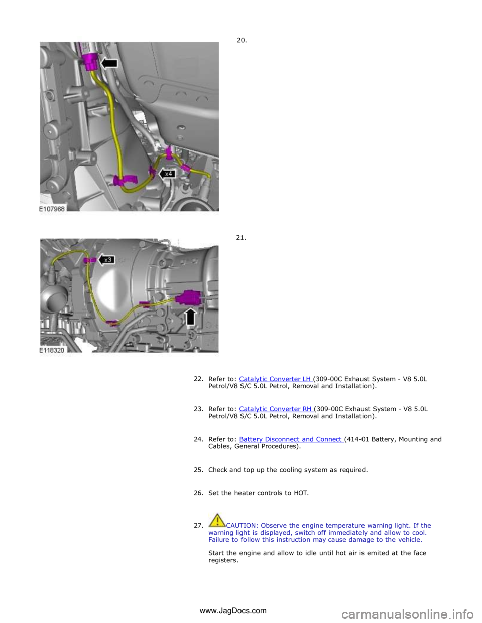
20.
21.
22.
Refer to: Catalytic Converter LH (309-00C Exhaust System - V8 5.0L Petrol/V8 S/C 5.0L Petrol, Removal and Installation).
23. Refer to: Catalytic Converter RH (309-00C Exhaust System - V8 5.0L Petrol/V8 S/C 5.0L Petrol, Removal and Installation).
24. Refer to: Battery Disconnect and Connect (414-01 Battery, Mounting and Cables, General Procedures).
25. Check and top up the cooling system as required.
26. Set the heater controls to HOT.
27. CAUTION: Observe the engine temperature warning light. If the
warning light is displayed, switch off immediately and allow to cool.
Failure to follow this instruction may cause damage to the vehicle.
Start the engine and allow to idle until hot air is emited at the face
registers. www.JagDocs.com
Page 1503 of 3039
28. CAUTION: Observe the engine temperature warning light. If the
warning light is displayed, switch off immediately and allow to cool.
Failure to follow this instruction may cause damage to the vehicle.
Raise the engine speed to 2000 RPM and maintain at 2000 RPM until the
engine cooling fan operates.
29. CAUTION: Switch off the engine and allow the coolant temperature
to go cold.
Switch the engine off and allow to cool.
30. Visually check the engine and cooling system for signs of coolant
leakage.
31. WARNINGS:
When releasing the cooling system pressure, cover the coolant
expansion tank cap with a thick cloth.
Since injury such as scalding could be caused by escaping steam or
coolant, make sure the vehicle cooling system is cool prior to carrying
out this procedure.
CAUTIONS:
Make sure the coolant level remains above the "COLD FILL RANGE"
lower level mark.
Anti-freeze concentration must be maintained at 50%.
NOTE: When the cooling system is warm, the coolant will be
approximately 10mm above the upper level mark on the expansion tank
with the cap removed.
Check and top-up the coolant if required.
32. Refer to: Transmission Fluid Level Check (307-01B Automatic Transmission/Transaxle - TDV6 3.0L Diesel /V8 5.0L Petrol/V8 S/C 5.0L
Petrol, General Procedures).
Page 1549 of 3039
Published: 11-May-2011
Exhaust System - V8 5.0L Petrol/V8 S/C 5.0L Petrol - Exhaust System
Diagnosis and Testing
Principle of Operation
For a detailed description of the exhaust system, refer to the relevant Description and Operation section of the workshop
manual. REFER to: (309-00C Exhaust System - V8 5.0L Petrol/V8 S/C 5.0L Petrol)
Exhaust System (Description and Operation), Exhaust System (Description and Operation), Exhaust System (Description and Operation).
Inspection and Verification
CAUTION: Diagnosis by substitution from a donor vehicle is NOT acceptable. Substitution of control modules does not
guarantee confirmation of a fault and may also cause additional faults in the vehicle being checked and/or the donor vehicle.
NOTE: Check and rectify basic faults before beginning diagnostic routines involving pinpoint tests.
1. Verify the customer concern.
2. Visually inspect for obvious signs of damage and system integrity.
3. If an obvious cause for an observed or reported concern is found, correct the cause (if possible) before proceeding to
the next step.
4. If the cause is not visually evident, verify the symptom and refer to the Symptom Chart, alternatively check for
Diagnostic Trouble Codes (DTCs) and refer to the DTC Index.
Symptom Chart
Symptom Possible Causes Action Excessively
noisy/leaking
exhaust
Exhaust
system/components Inspect exhaust system. Rectify leaks and install new components as
required. Refer to Removal and Installation instructions in this section Loss of power
Restricted exhaust system
Exhaust sound
enhancement valve stuck
closed
Fuel system
Ignition system
Electronic engine control Inspect exhaust system. Install new exhaust components as required.
Refer to Removal and Installation instructions in this section. Check for
fuel, ignition and electronic engine control system DTCs and refer to the
relevant DTC Index
DTC Index
For a list of Diagnostic Trouble Codes (DTCs) that could be logged in the Engine Control Module (ECM), please refer to Section
303-14. REFER to:
Electronic Engine Controls (303-14C Electronic Engine Controls - V8 5.0L Petrol, Diagnosis and Testing), Electronic Engine Controls (303-14D Electronic Engine Controls - V8 S/C 5.0L Petrol, Diagnosis and Testing). Mechanical
Leaks
Metal fatigue
Pipes
Catalytic converter
Muffler(s)
Joints
Mountings
Clearance around components Visual Inspection
Page 1595 of 3039
Published: 28-Jul-2014
Fuel Tank and Lines - V8 5.0L Petrol/V8 S/C 5.0L Petrol - Fuel Tank and
Lines
Diagnosis and Testing
Principle of Operation
For a detailed description of the fuel tank and lines system and operation, refer to the relevant Description and Operation
section of the workshop manual. REFER to: (310-01C Fuel Tank and Lines - V8 5.0L Petrol/V8 S/C 5.0L Petrol)
Fuel Tank and Lines (Description and Operation), Fuel Tank and Lines (Description and Operation), Fuel Tank and Lines (Description and Operation).
Inspection and Verification
WARNINGS:
Eye protection must be worn at all times when working on or near any fuel related components. Failure to follow this
instruction may result in personal injury.
This procedure involves fuel handling. Be prepared for fuel spillage at all times and always observe fuel handling
precautions. Failure to follow this instruction may result in personal injury.
After carrying out repairs, the fuel system must be checked visually for leaks. This should be done after the engine has
been run, but with the engine switched OFF. Failure to follow this instruction may result in personal injury.
If taken internally, DO NOT induce vomiting. Seek immediate medical attention. Failure to follow this instruction may
result in personal injury.
If fuel contacts the eyes, flush the eyes with cold water or eyewash solution and seek medical attention. Failure to follow
this instruction may result in personal injury.
Wash hands thoroughly after handling, as prolonged contact may cause irritation. Should irritation develop, seek medical
attention. Failure to follow this instruction may result in personal injury.
CAUTIONS:
Before disconnecting any part of the system, it is imperative that all dust, dirt and debris is removed from around
components to prevent ingress of foreign matter into the fuel system. Failure to follow this instruction may result in damage to
the vehicle.
It is essential that absolute cleanliness is observed when working with these components. Always install blanking plugs
to any open orifices or lines. Failure to follow this instruction may result in damage to the vehicle.
Diagnosis by substitution from a donor vehicle is NOT acceptable. Substitution of control modules does not guarantee
confirmation of a fault, and may also cause additional faults in the vehicle being tested and/or the donor vehicle.
NOTES:
Check and rectify basic faults before beginning diagnostic routines involving pinpoint tests.
When measuring fuel sender resistance values with a multimeter, it is critical to use the correct multimeter setting. The
multimeter should not be on the 'Auto' setting and must be set to 'Manual'. This will help prevent incorrect diagnosis and
unnecessary replacement of fuel senders. If the multimeter range is set at 'Auto' then, during a sweep of the sender from 50
Ohms to 998 Ohms, the multimeter has to change its measurement range. For approximately 1 second, during the range switch
over point, the multimeter display indicates an open circuit. This can lead to a mis-diagnosis of a fuel sender fault.
1. Verify the customer concern
2. Visually inspect for obvious signs of damage and system integrity