2010 JAGUAR XFR check engine
[x] Cancel search: check enginePage 1665 of 3039
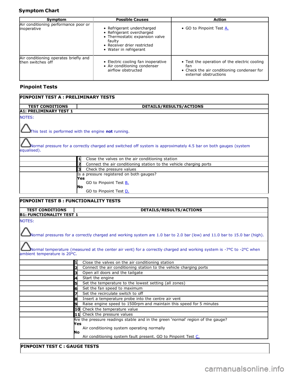
Symptom Chart
Symptom Possible Causes Action Air conditioning performance poor or
inoperative
Refrigerant undercharged
Refrigerant overcharged
Thermostatic expansion valve
faulty
Receiver drier restricted
Water in refrigerant
GO to Pinpoint Test A. Air conditioning operates briefly and
then switches off
Electric cooling fan inoperative
Air conditioning condenser
airflow obstructed
Test the operation of the electric cooling
fan
Check the air conditioning condenser for
external obstructions Pinpoint Tests
PINPOINT TEST A : PRELIMINARY TESTS TEST CONDITIONS DETAILS/RESULTS/ACTIONS A1: PRELIMINARY TEST 1 NOTES:
This test is performed with the engine not running.
Normal pressure for a correctly charged and switched off system is approximately 4.5 bar on both gauges (system
equalised). 1 Close the valves on the air conditioning station 2 Connect the air conditioning station to the vehicle charging ports 3 Check the pressure values Is a pressure registered on both gauges? Yes
GO to Pinpoint Test B. No
GO to Pinpoint Test D.
PINPOINT TEST B : FUNCTIONALITY TESTS TEST CONDITIONS DETAILS/RESULTS/ACTIONS B1: FUNCTIONALITY TEST 1 NOTES:
Normal pressures for a correctly charged and working system are 1.0 bar to 2.0 bar (low) and 11.0 bar to 15.0 bar (high).
Normal temperature (measured at the center air vent) for a correctly charged and working system is -7°C to -2°C when
ambient temperature is 20°C. 1 Close the valves on the air conditioning station 2 Connect the air conditioning station to the vehicle charging ports 3 Open all doors and the tailgate 4 Start the engine 5 Set the temperature to the lowest setting (all zones) 6 Set the fan speed to maximum 7 Set the recirculate switch to off 8 Insert a temperature probe into the centre air vent 9 Raise engine speed to 1500rpm and maintain this speed for 5 minutes 10 Check the temperature value 11 Check the pressure values Are the pressure readings stable and in the green 'normal' region of the gauge? Yes
Air conditioning system operating normally No
Air conditioning system fault present. GO to Pinpoint Test C.
PINPOINT TEST C : GAUGE TESTS
Page 1666 of 3039
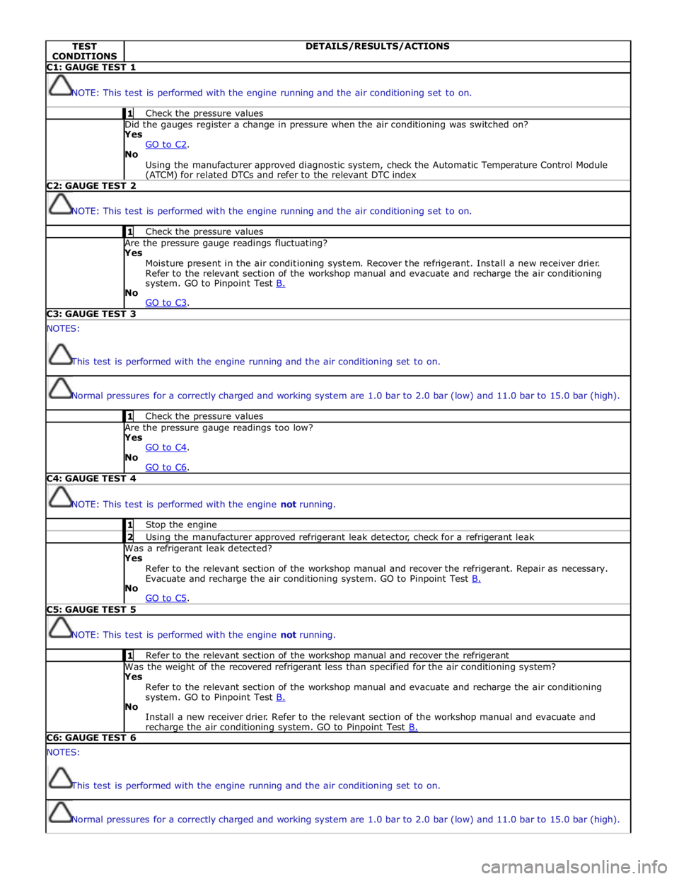
TEST
CONDITIONS DETAILS/RESULTS/ACTIONS C1: GAUGE TEST 1
NOTE: This test is performed with the engine running and the air conditioning set to on. 1 Check the pressure values Did the gauges register a change in pressure when the air conditioning was switched on? Yes
GO to C2. No
Using the manufacturer approved diagnostic system, check the Automatic Temperature Control Module (ATCM) for related DTCs and refer to the relevant DTC index C2: GAUGE TEST 2
NOTE: This test is performed with the engine running and the air conditioning set to on. 1 Check the pressure values Are the pressure gauge readings fluctuating? Yes
Moisture present in the air conditioning system. Recover the refrigerant. Install a new receiver drier.
Refer to the relevant section of the workshop manual and evacuate and recharge the air conditioning
system. GO to Pinpoint Test B. No
GO to C3. C3: GAUGE TEST 3 NOTES:
This test is performed with the engine running and the air conditioning set to on.
Normal pressures for a correctly charged and working system are 1.0 bar to 2.0 bar (low) and 11.0 bar to 15.0 bar (high). 1 Check the pressure values Are the pressure gauge readings too low? Yes
GO to C4. No
GO to C6. C4: GAUGE TEST 4
NOTE: This test is performed with the engine not running. 1 Stop the engine 2 Using the manufacturer approved refrigerant leak detector, check for a refrigerant leak Was a refrigerant leak detected? Yes
Refer to the relevant section of the workshop manual and recover the refrigerant. Repair as necessary.
Evacuate and recharge the air conditioning system. GO to Pinpoint Test B. No
GO to C5. C5: GAUGE TEST 5
NOTE: This test is performed with the engine not running. 1 Refer to the relevant section of the workshop manual and recover the refrigerant Was the weight of the recovered refrigerant less than specified for the air conditioning system? Yes
Refer to the relevant section of the workshop manual and evacuate and recharge the air conditioning
system. GO to Pinpoint Test B. No
Install a new receiver drier. Refer to the relevant section of the workshop manual and evacuate and recharge the air conditioning system. GO to Pinpoint Test B. C6: GAUGE TEST 6 NOTES:
This test is performed with the engine running and the air conditioning set to on.
Normal pressures for a correctly charged and working system are 1.0 bar to 2.0 bar (low) and 11.0 bar to 15.0 bar (high).
Page 1667 of 3039
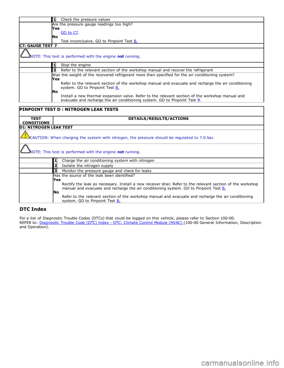
1 Check the pressure values Are the pressure gauge readings too high? Yes
GO to C7. No
Test inconclusive. GO to Pinpoint Test B. C7: GAUGE TEST 7
NOTE: This test is performed with the engine not running. 1 Stop the engine 2 Refer to the relevant section of the workshop manual and recover the refrigerant Was the weight of the recovered refrigerant more than specified for the air conditioning system? Yes
Refer to the relevant section of the workshop manual and evacuate and recharge the air conditioning
system. GO to Pinpoint Test B. No
Install a new thermal expansion valve. Refer to the relevant section of the workshop manual and
evacuate and recharge the air conditioning system. GO to Pinpoint Test B.
PINPOINT TEST D : NITROGEN LEAK TESTS TEST
CONDITIONS DETAILS/RESULTS/ACTIONS D1: NITROGEN LEAK TEST
CAUTION: When charging the system with nitrogen, the pressure should be regulated to 7.0 bar.
NOTE: This test is performed with the engine not running. 1 Charge the air conditioning system with nitrogen 2 Isolate the nitrogen supply 3 Monitor the pressure gauge and check for leaks Has the source of the leak been identified?
Yes
Rectify the leak as necessary. Install a new receiver drier. Refer to the relevant section of the workshop
manual and evacuate and recharge the air conditioning system. GO to Pinpoint Test B. No
Refer to the relevant section of the workshop manual and evacuate and recharge the air conditioning system. GO to Pinpoint Test B.
DTC Index
For a list of Diagnostic Trouble Codes (DTCs) that could be logged on this vehicle, please refer to Section 100-00.
REFER to: Diagnostic Trouble Code (DTC) Index - DTC: Climate Control Module (HVAC) (100-00 General Information, Description and Operation).
Page 1687 of 3039
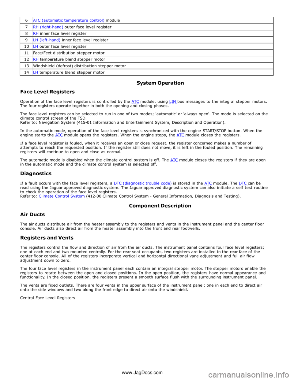
7 RH (right-hand) outer face level register 8 RH inner face level register 9 LH (left-hand) inner face level register 10 LH outer face level register 11 Face/Feet distribution stepper motor 12 RH temperature blend stepper motor 13 Windshield (defrost) distribution stepper motor 14 LH temperature blend stepper motor
Face Level Registers System Operation
Operation of the face level registers is controlled by the ATC module, using LIN bus messages to the integral stepper motors. The four registers operate together in both the opening and closing phases.
The face level registers can be selected to run in one of two modes; 'automatic' or 'always open'. The mode is selected on the
climate control screen of the TSD.
Refer to: Navigation System (415-01 Information and Entertainment System, Description and Operation).
In the automatic mode, operation of the face level registers is synchronized with the engine START/STOP button. When the
engine starts the ATC module opens the registers. When the engine stops, the ATC module closes the registers.
If a face level register is fouled, when it receives an open or close request, the register concerned makes a number of
attempts to reach the requested position. If the register still does not move, it is left in the fouled position. The remaining
registers will continue to open and close as normal.
The automatic mode is disabled when the climate control system is off. The ATC module closes the registers if they are open in the automatic mode and the climate control system is selected off.
Diagnostics
If a fault occurs with the face level registers, a DTC (diagnostic trouble code) is stored in the ATC module. The DTC can be read using the Jaguar approved diagnostic system. The Jaguar approved diagnostic system can also initiate a self test routine
to check the operation of the face level registers.
Refer to: Climate Control System (412-00 Climate Control System - General Information, Diagnosis and Testing).
Air Ducts Component Description
The air ducts distribute air from the heater assembly to the registers and vents in the instrument panel and the center floor
console. Air ducts also direct air from the heater assembly into the front and rear footwells.
Registers and Vents
The registers control the flow and direction of air from the air ducts. The instrument panel contains four face level registers;
one at each end and two mounted centrally. For the rear seat occupants, two registers are installed in the rear face of the
center floor console. All of the registers incorporate vertical and horizontal directional vane adjustment and full air flow
adjustment down to zero.
The four face level registers in the instrument panel each contain an integral stepper motor. The stepper motors enable the
registers to rotate between the open and closed positions. In the open position, the registers have normal appearance and
functionality. In the closed position, the registers present a smooth surface flush with the surrounding instrument panel.
The vents are fixed outlets. There are four vents in the upper surface of the instrument panel; one in each end to direct air
onto the side windows and two along the front edge to direct air onto the windshield.
Central Face Level Registers
www.JagDocs.com
Page 1771 of 3039
14. WARNINGS:
Never remove the coolant expansion tank cap under any
circumstances while the engine is operating. Failure to follow this
instruction may result in personal injury.
To avoid having scalding hot coolant or steam blowing out of the
cooling system, use extreme care when removing the coolant pressure
cap from a hot cooling system. Wait until the engine has cooled, then
wrap a thick cloth around the coolant pressure cap and turn it slowly
until the pressure begins to release. Step back while the pressure is
released from the system. When certain all the pressure has been
released (still with a cloth) turn and remove the coolant pressure cap
from the coolant expansion tank. Failure to follow these instructions may
result in personal injury.
Release the cooling system pressure.
15. Fill the cooling system up to the MAX mark on the coolant expansion
tank using a fifty percent mixture of Jaguar Premium Cooling System
Fluid or equivalent, meeting Jaguar specification WSS M97B44-D and
fifty percent water.
16. Install the coolant expansion tank pressure cap.
17. Raise the vehicle.
18. Check all coolant hoses for visible signs of coolant leaks.
19. Install the air deflector.
Refer to: Air Deflector (501-02, Removal and Installation).
www.JagDocs.com
Page 1785 of 3039
The functionality for each of the above warning indicators is described in the following sections:
1 and 2. Turn Signal Indicators
The turn signal indicators are controlled by the CJB on receipt of medium speed CAN bus signals from the instrument cluster.
The instrument cluster outputs a voltage to the turn signal indicator switch. The switch contains resistors of different values.
When the switch is operated in either the LH or RH direction, the voltage is passed to a ground connection in the instrument cluster which detects the reduced voltage supplied via the resistors. When the turn signal indicator switch is operated in the
LH or RH direction, the instrument cluster detects the ground voltage and determines whether a LH or RH selection is made.
The instrument cluster transmits a medium speed CAN message to the CJB for operation of the applicable turn signal indicators. The message can contain a number of states for each possible switch position and also an out of range low and
high state for circuit faults and an initial value for the switch neutral position. The turn signal indicators are not subject to the
3 second indicator check when the ignition is switched on.
The RJB (rear junction box) software controls the flash rate of the warning indicator which sends 'ON' and 'OFF' signals to the
instrument cluster which flashes the indicators in a green color. During normal operation, the warning indicator flashes slowly,
accompanied simultaneously by a sound from the instrument cluster sounder. If a fault exists, the RJB transmits a message to the instrument cluster which responds by displaying an appropriate message in the message center.
The hazard warning indicators are controlled by the CJB on receipt of a completed ground path from the hazard warning indicator switch. The CJB outputs a medium speed CAN message to the instrument cluster which operates both the LH and RH turn signal indicators simultaneously. The hazard warning indicators can operate with the ignition switched off, therefore the
CAN message from the CJB will also carry a 'wake-up' message for the instrument cluster. 3. Brake Warning Indicator
This warning indicator is displayed in a red or amber color (dependant on market) as a brake symbol in all markets except
United States of America (USA) which have the word 'BRAKE' in place of the symbol. The indicator is controlled by high speed
CAN messages from the ABS module and the parking brake control module. The indicator is illuminated in a red color for a 3 second indicator check when the ignition is switched on.
The instrument cluster monitors the fluid level in the brake fluid reservoir using a hardwired level switch. If the fluid level falls
to below a determined level, the switch contact is broken and the ABS module detects the low fluid level condition. The instrument cluster illuminates the warning indicator and simultaneously displays a 'BRAKE FLUID LOW' message in the
message center.
NOTE: If both the brake warning indicator and the ABS warning indicator illuminate simultaneously, a major fault in the brake system will have occurred.
The warning indicator also displays parking brake status. When the parking brake is applied, the warning indicator will be
illuminated by the instrument cluster and, if the vehicle is moving, the message 'PARK BRAKE APPLIED' will be also displayed
in the message center in response to a CAN message from the parking brake control module.
If a condition exists where the parking brake cannot be applied, the parking brake control module issues a CAN message to the instrument cluster which flashes the warning lamp on and off and is accompanied with a message 'CANNOT APPLY PARK BRAKE'.
If a fault occurs in the parking brake system, the parking brake control module issues a CAN message to the instrument cluster which illuminates the warning indicator and displays the message 'PARK BRAKE FAULT' in the message
center.
4. Forward Alert Indicator
The forward alert system uses the components of the adaptive speed control system to alert the driver of the presence of a
vehicle ahead. The system can be turned on and off using a switch located in the auxiliary lighting switch when the adaptive
speed control system is off. The indicator is illuminated in an amber color for a 3 second indicator check when the ignition is
switched on.
The forward alert system is controlled by the adaptive speed control module. When the switch is pressed, the forward alert
system is activated and the adaptive speed control module issues a forward alert active message on the high speed CAN bus to the instrument cluster. The forward alert icon in the instrument cluster will illuminate in an amber color and a 'FORWARD
ALERT' message will be displayed in the message center. When the button is pressed a second time, the module issues a
forward alert off CAN message. The forward alert system will be deactivated, the forward alert icon will go off and a message 'FORWARD ALERT OFF' will be displayed in the message center.
5. Automatic Speed Limiter (ASL) Indicator
The ASL is controlled by the ECM (engine control module). An ASL switch is located in the floor console, adjacent to the gear
selector lever. When the ASL switch is pressed, this is sensed by the ECM which issues a high speed CAN message to the instrument cluster. The instrument cluster illuminates the ASL warning indicator in an amber color to show the driver that ASL
is active. The driver sets the required speed using the speed control SET +/- switches on the steering wheel. The selected
speed is shown by the message ' LIMITER SET XXX MPH / K/MH' in the message center. The indicator is illuminated in an
amber color for a 3 second indicator check when the ignition is switched on. ASL can be deselected by pressing the ASL switch,
by depressing the throttle pedal initiating kick-down or by pressing the 'cancel' switch on the steering wheel. The ASL indicator
will go off and the message center will display the message 'limiter cancelled' for 4 seconds. If a fault occurs in the ASL
system, the ECM will send a message to the instrument cluster to illuminate the ASL indicator and display the message 'LIMITER NOT AVAILABLE'.
Page 1786 of 3039
6. Adaptive Speed Control Indicator
The adaptive speed control system is controlled by the adaptive speed control module. Operation of the SET +/- switches on
the steering wheel will activate the system. Operation of the switches is detected by the adaptive speed control module. The
module issues a high speed CAN message to the instrument cluster which illuminates the adaptive speed control indicator, when the system is in 'follow mode', in an amber color and displays a 'SETSPEED XXX MPH / KM/H' message in the message
center. The indicator is illuminated in an amber color for a 3 second indicator check when the ignition is switched on.
7. Anti-lock Braking System (ABS) Warning Indicator
The ABS warning indicator is controlled by the ABS module. If a fault in the ABS system is detected by the ABS module, the module issues a high speed CAN message to the instrument cluster to illuminate the ABS warning indicator in an amber color and display the message 'ABS FAULT' in the instrument cluster. The indicator is illuminated in an amber color for a 3 second
indicator check when the ignition is switched on. If a fault is present when the ignition is on, the bulb will remain illuminated
after the 3 second indicator check period.
NOTES:
The 'ABS FAULT' message is not displayed in NAS markets).
If both the ABS warning indicator and the brake warning indicator illuminate simultaneously, a major fault in the brake system will have occurred.
On NAS vehicles, the ABS warning indicator is also used for parking brake operation. The NAS warning indicator does not have 'ABS' on the icon and will function as described previously for the parking brake operation of the brake warning indicator.
8. Engine Malfunction Indicator Lamp (MIL)
The MIL warning indicator is controlled by the ECM and illuminated by the instrument cluster on receipt of a message on the high speed CAN bus from the ECM. The indicator is illuminated in an amber color for a 3 second indicator check when the ignition is switched on.
If the MIL remains illuminated after the engine is started or illuminates when driving, a fault is present and must be
investigated at the earliest opportunity. Illumination of the MIL warning indicator alerts the driver to an OBD (on-board
diagnostic) fault which will cause excessive emissions output. This may relate to either an engine management system fault or
a transmission.
9. Tire Pressure Monitoring System (TPMS) Warning Indicator
The TPMS warning indicator is illuminated by the instrument cluster on receipt of a medium speed CAN message from the TPMS module. The indicator is illuminated in an amber color for a 3 second indicator check when the ignition is switched on.
If the indicator illuminates and is accompanied by the message 'TYRE PRESSURE SYSTEM FAULT' in the message center, then a
TPMS fault has occurred. If the indicator illuminates and accompanied by a different message, then a low tire pressure has
been detected, a spare wheel has been fitted or a TPMS sensor has failed.
10. Airbag Warning Indicator
The airbag warning indicator is controlled by the instrument cluster. The indicator is illuminated in an amber color for the 3
second indicator check when the ignition is switched on. The indicator remains illuminated after the 3 second period has
expired until the instrument cluster receives a turn off message on the high speed CAN bus from the RCM (restraints control module).
11. Front Fog Lamp Indicator
The green colored front fog lamp indicator is controlled by the CJB and illuminated by the instrument cluster on receipt of a front fog lamp on message on the medium speed CAN bus from the CJB. The indicator is illuminated for as long as the front fog lamps are active. The front fog lamp indicator is not subject to the 3 second indicator check when the ignition is switched
on.
12. Dynamic Stability Control (DSC) Indicator
The DSC warning lamp is controlled by the ABS module and illuminated by the instrument cluster in response to messages received on the high speed CAN bus. The indicator is illuminated in an amber color for the 3 second indicator check when the ignition is switched on. The DSC warning indicator, are permanently illuminated in an amber color if the instrument cluster
receives a high speed CAN message from the ABS module relating to one of the following faults:
Traction control fault
Yaw control fault
Engine drag torque control fault
Panic Brake Assist (PBA) fault
Signal missing relating to either traction control active, yaw control active or DSC switch input.
The above faults will also generate an applicable DSC and ABS warning message in the message center. The DSC warning
indicator will flash at 2 Hz for if the traction control or yaw control is active when the DSC system is enabled. If the DSC
system is switched off, the warning indicator will be permanently illuminated until the DSC system is subsequently
re-activated.
13. Safety Belt Warning Indicator
The safety belt warning indicator operates for both the driver and passenger safety belts. The warning indicator is controlled by
Page 1787 of 3039
the RCM and illuminated by the instrument cluster on receipt of high speed CAN bus messages. The safety belt warning indicator is not subject to the 3 second indicator check when the ignition is switched on.
The operation of the passenger seat buckle switch is as described below with the exception that the instrument cluster must
receive a hardwired signal from the belt minder control module to indicate that a passenger is occupying the seat.
The safety belt warning indicator is subject to a timer. The warning indicator is activated when the following conditions exist:
Ignition is switched on
One of the front seat belts is unbuckled
USA market only - 75 seconds has elapsed after ignition on mode is selected
Vehicle is not in reverse gear
Vehicle speed is more than 8 km/h (5 mph).
Once the above parameters are met, the instrument cluster flashes the warning indicator at 2 Hz for 10 seconds accompanied
by a simultaneous chime. After 10 seconds the chime ceases and the warning indicator is permanently illuminated for 20
seconds. This sequence is repeated every 30 seconds until one of the following events occurs:
300 seconds has elapsed
The safety belt of the occupied front seats is fastened
The ignition is switched to off mode
The vehicle speed decreases to below 5 km/h (3 mph).
NOTE: On USA market vehicles, the warning indicator in not permanently illuminated.
The safety belt minder function cannot be disabled. The seat belt minder function can be disabled.
Refer to: Safety Belt System (501-20A Safety Belt System, Description and Operation). 14. Side Lamp Indicator
The instrument cluster controls the green colored side lamp indicator on receipt of a side lamp status message on the medium
speed CAN bus from the CJB and the auxiliary junction box. The lighting switch on the LH steering column multifunction switch is connected to the instrument cluster. Selections using this switch are detected by the cluster which requests the side or
headlamp operation via a message to the CJB and the RJB. The CJB and the RJB responds with a side lamp active message and the cluster illuminates the side lamp indicator. The side lamp indicator is not subject to the 3 second indicator check when
the ignition is switched on.
15. High Beam Indicator
The instrument cluster controls the blue colored high beam indicator on receipt of a high beam status message on the medium
speed CAN bus from the CJB. The lighting switch on the LH steering column multifunction switch is connected to the instrument cluster. High beam or flash selections using this switch are detected by the cluster which requests the light
operation via a CAN message to the CJB. The CJB responds with a high beam active message and the cluster illuminates the high beam indicator. The high beam indicator is not subject to the 3 second indicator check when the ignition is switched on.
16. Rear Fog Lamp Indicator
The amber colored rear fog lamp indicator is controlled by the auxiliary junction box and illuminated by the instrument cluster
on receipt of a rear fog lamp on message on the medium speed CAN bus from the RJB. The indicator is illuminated for as long as the rear fog lamps are active. The rear fog lamp indicator is not subject to the 3 second indicator check when the ignition is
switched on.
SPEEDOMETER
The speedometer is driven by high speed CAN signals transmitted by the ABS module. The wheel speeds are measured by sensors reading the rotational speed of the rear wheels from toothed targets on the hubs. An average of the two wheel speeds
are passed from the sensors to the ABS module in the form of pulsed signals. The ABS module converts these signals into a speed output on the high speed CAN to the instrument cluster. The same speed outputs from the wheel speed sensors are also used to calculate the distance the vehicle has travelled.
TACHOMETER
The tachometer is driven by an engine speed signal transmitted on the high speed CAN from the ECM. The signal is derived from the CKP (crankshaft position) sensor. The signal is received by the instrument cluster microprocessor and the output from
the microprocessor drives the tachometer.
FUEL GAGE
The fuel gage is controlled by CAN messages from the RJB. The RJB reads the values output by the fuel level sensors every 131 ms and transmits a fuel tank contents value, corrected for battery voltage, in a CAN message to the instrument cluster. A fuel pump symbol is displayed to the left of the linear gage. An arrow above the symbol shows the driver on which side of the
vehicle the fuel filler cap is located. Above the linear fuel gage, is a LCD (liquid crystal display) area which displays odometer
and trip readouts. When a trip computer function is selected, these are replaced by a trip computer display for the trip function
selected.
LIQUID CRYSTAL DISPLAY
In the area above and below the message center is a LCD display. The area below the message center displays a linear fuel www.JagDocs.com