2010 JAGUAR XFR display
[x] Cancel search: displayPage 1873 of 3039
Published: 02-Apr-2014
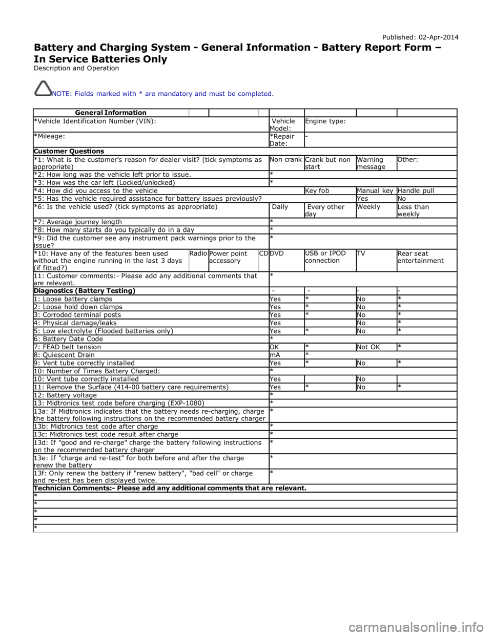
Battery and Charging System - General Information - Battery Report Form – In Service Batteries Only
Description and Operation
NOTE: Fields marked with * are mandatory and must be completed.
General Information *Vehicle Identification Number (VIN):
Vehicle
Model: Engine type: *Mileage:
*Repair
Date: - Customer Questions *1: What is the customer’s reason for dealer visit? (tick symptoms as appropriate) Non crank
Crank but non
start Warning message Other: *2: How long was the vehicle left prior to issue. * *3: How was the car left (Locked/unlocked) * *4: How did you access to the vehicle Key fob Manual key Handle pull *5: Has the vehicle required assistance for battery issues previously? Yes No *6: Is the vehicle used? (tick symptoms as appropriate) Daily
Every other day Weekly
Less than weekly *7: Average journey length * *8: How many starts do you typically do in a day * *9: Did the customer see any instrument pack warnings prior to the
issue? * *10: Have any of the features been used
without the engine running in the last 3 days (if fitted?) Radio
Power point
accessory CD DVD USB or IPOD
connection TV
Rear seat
entertainment 11: Customer comments:- Please add any additional comments that
are relevant. * Diagnostics (Battery Testing) - - - - 1: Loose battery clamps Yes * No * 2: Loose hold down clamps Yes * No * 3: Corroded terminal posts Yes * No * 4: Physical damage/leaks Yes No * 5: Low electrolyte (Flooded batteries only) Yes * No * 6: Battery Date Code * 7: FEAD belt tension OK * Not OK * 8: Quiescent Drain mA * 9: Vent tube correctly installed Yes * No * 10: Number of Times Battery Charged: * 10: Vent tube correctly installed Yes No 11: Remove the Surface (414-00 battery care requirements) Yes * No * 12: Battery voltage * 13: Midtronics test code before charging (EXP-1080) * 13a: If Midtronics indicates that the battery needs re-charging, charge
the battery following instructions on the recommended battery charger * 13b: Midtronics test code after charge * 13c: Midtronics test code result after charge * 13d: If "good and re-charge" charge the battery following instructions
on the recommended battery charger * 13e: If "charge and re-test" for both before and after the charge
renew the battery * 13f: Only renew the battery if "renew battery", "bad cell" or charge
and re-test has been displayed twice. * Technician Comments:- Please add any additional comments that are relevant. * * * * *
Page 1882 of 3039
11 Secondary battery 12 Dual Battery Junction Box (DBJB) 13 Rear Junction Box (RJB) 14 Megafuse 15 Battery Junction box (BJB) 16 Primary battery
System Operation BATTERY MONITORING SYSTEM - TD4 2.2L DIESEL VEHICLES ONLY
Periodically the battery monitoring system module will instigate a self-calibration routine. To self calibrate, the battery
monitoring system first charges the battery to its full condition.
NOTE: If the vehicle is only driven for short periods the charging process could take a number of days to complete.
Once the battery is fully charged, the battery monitoring system will discharge the battery to approximately 75% of its full
state of charge, but never lower than 12.2 V. The time taken to complete this part of the routine is dependent on the electrical
load on the vehicle.
When the second part of the routine has been successfully completed, the battery monitoring system will return the battery to
its optimum level of charge. The optimum level of charge will be between 12.6 V and 15 V, depending on battery condition,
temperature and loading.
The battery monitoring system module also monitors the battery condition with the engine switched off. If a low voltage
condition is detected the module can request the infotainment system is switched off to protect battery voltage. Once the
infotainment system has been switched off, the vehicle must be run for at least 5 minutes to charge the battery before the
infotainment system can be operated with the engine switched off.
BATTERY MONITORING SYSTEM - SINGLE AND DUAL BATTERY SYSTEM VEHICLES
When the ignition is off (power mode 0), the BMS control module records the primary battery state of charge and begins to
monitor the battery condition from this point.
If the battery state of charge falls by 7%, the BMS control module will monitor the primary battery for 5 minutes. If after the 5
minute monitoring period, the primary battery charge has continued to fall due to the quiescent drain current being too high,
the BMS control module will determine that some control modules are still 'awake'. The BMS control module sends a shutdown
message on the LIN (local interconnect network) bus to the GWM (Gateway Module). The GWM sends a CAN (controller area
network) bus message on both the medium and high speed networks to all control modules, requesting them to shutdown.
The BMS control module will monitor the primary battery state of charge for a further 5 minutes and determine if the primary
battery state of charge is still dropping. If a quiescent drain current continues, the primary battery state of charge will
continue to drop. If the state of charge falls to 12% of the initial monitoring value, the BMS control module determines that
one or more control modules are still awake and a failure to respond to the shutdown request may indicate an error state
within the control module(s).
BMS Low Battery Warning and Energy Management Messages
The BMS continuously monitors the condition of the primary vehicle battery. If excessive battery discharge occurs, the system
will begin to shut down non-essential electrical systems in order to protect the battery.
If the BMS calculates that battery condition is not within set parameters, there are 3 messages that can be displayed, 2 on the
touch screen and 1 on the message center. These inform the user that the battery is either at a low level of charge or the
engine-off power consumption limit has been exceeded.
Low Battery - Please switch engine on or system will shutdown in 3 minutes: is displayed as a Warning on the
touch screen if the engine is not running. This indicates that the battery has fallen below a predefined threshold. As
soon as the battery is charged back above this threshold then the message will be removed.
Low Battery - Please start your engine is displayed on the message center if the engine is not running. This indicates
that the battery has fallen below a predefined threshold. As soon as the battery is charged back above this threshold
then the message will be removed or it can be manually removed by pressing 'OK'.
System will shut down in 3 minutes: is displayed as an Energy management on the touch screen if the engine is not
running, and system features are causing excessive battery discharge. After 3 minutes the BMS will begin shutting
down vehicle systems. Normal system operation will resume when the engine is started.
This is based on a percentage of battery capacity available for the customer to use with the engine off. The percentage can
change based upon several factors.
Once triggered, the resetting of this message will not occur until the vehicle is driven for 10 minutes with the engine running
(to allow the battery to recoup any lost charge). However, if the engine is run for less than 10 minutes, the message will only
be displayed after an additional 5 minutes with the ignition on but engine off.
BMS Control Module Self Calibration
Periodically the BMS control module will instigate a self-calibration routine. To self calibrate, the battery monitoring system www.JagDocs.com
Page 1885 of 3039

is operated to crank the engine. The GWM is connected to the ABS (Anti-lock Brake System) control module via the high speed
CAN bus. With the vehicle stationary and the engine off after an ECO engine stop, when the driver releases the brake pedal
the ABS control module senses the reduction in brake pressure. This change of brake pressure state is sent as a high speed
CAN message which is received by the GWM and the ECM. The GWM reacts within 105ms to instruct the DBM via the LIN bus
to operate the two contactors in the DBJB to supply the sensitive loads from the secondary battery and supply the TSS motor
direct from the primary battery.
When the engine is running and the generator is supplying power to the vehicle systems, the GWM again instructs the DBM to
operate the two contactors in the DBJB to supply all vehicle systems from the primary battery and the generator and to isolate
the secondary battery.
Secondary Battery Charging
The DBM also controls the charging of the secondary battery. The GWM contains electrical load management software and
monitors both batteries for their state of charge. The primary battery is monitored by the BMS control module which is
connected to the DBM via the LIN bus. The DBM communicates the primary battery condition to the GWM via a LIN bus
connection. The GWM sends a signal to the DBM via the LIN bus to instruct it to apply charging from the generator to the
secondary battery when required. The contactor 2 is closed by the DBJB to complete the secondary battery circuit, and the
generator output is applied to the secondary battery to charge it.
The generator output is controlled by the GWM which monitors and controls the electrical load management system. The
generator is connected to the GWM by a LIN bus allowing the GWM to control the output of the generator to maintain electrical
system load requirements and battery charging.
Electrical Load Management
The electrical load management is controlled by the GWM and the BMS control module.
The GWM will monitor the vehicle system power loads before and during an ECO engine stop.
Before an ECO engine stop, the GWM will transmit a signal to system control modules on the CAN bus to request a power save
on all electrical loads and set a minimum electrical value override. The GWM monitors the vehicle electrical loads and will
inhibit a ECO engine stop until the load current is at a value low enough to be supported by the secondary battery.
If the electrical loads cannot be reduced sufficiently, the GWM will inhibit the ECO engine stop.
When the engine is stopped after an ECO engine stop, the GWM will continue to monitor the primary battery state of charge.
If the primary or secondary battery voltage falls below 11.0V, a level which will result in degraded starting performance or
possible primary battery damage, the GWM will initiate an engine start.
System Inhibits
The ECO stop/start system is inhibited if the dual battery system is not be capable of preventing electrical loads on the
vehicle being subject to unacceptably low voltage levels during ECO stop/start operations due to a fault.
ECO stop/start inhibit monitoring of the primary battery is performed by the BMS control module. If the primary battery voltage
is too low to support an ECO stop/start, then the BMS control module will send a message to the GWM on the LIN bus to
suspend ECO stop/start.
The GWM monitors the secondary battery and the dual battery system components. Any fault found will cause the GWM to
inhibit ECO stop/start and the GWM will record a DTC (diagnostic trouble code).
Fault Diagnosis
The GWM performs passive and active diagnostics on the dual battery system to determine the status of the system
components.
Passive diagnostics can detect faults in the DBJB and can check for stuck open or closed contactors and failure of DBM
contactor command signals.
Active diagnostics is a routine to test the capability of the contactors to respond to open or close command signals sent from
the GWM to the DBM. This routine also checks the FET's (Field Effect Transistors) activate as required. (Refer to Dual Battery
Junction Box below for description of FET operation)
The GWM will also check the dual battery system components for faults in a controlled environment when the generator is
providing a charging output. This will ensure that the detection of a fault will not result in sensitive electrical loads being
subjected to low voltage which may occur during an ECO stop/start with a fault present.
The GWM will illuminate the charge warning indicator in the instrument cluster if fault is detected in the dual battery system
which will result in a degraded power supply.
If a fault is detected the GWM transmits a CAN message to inhibit ECO stop/start operation. In some cases it will record a
DTC, display a warning message in instrument cluster and also illuminate charge warning indicator.
PRIMARY BATTERY - ALL VEHICLES Component Description
The primary battery is located in a plastic tray under the luggage compartment floor in the right side of the luggage
compartment, adjacent to the spare wheel. The battery is vented via a tube which is connected with a T piece to the vent from
Page 1892 of 3039
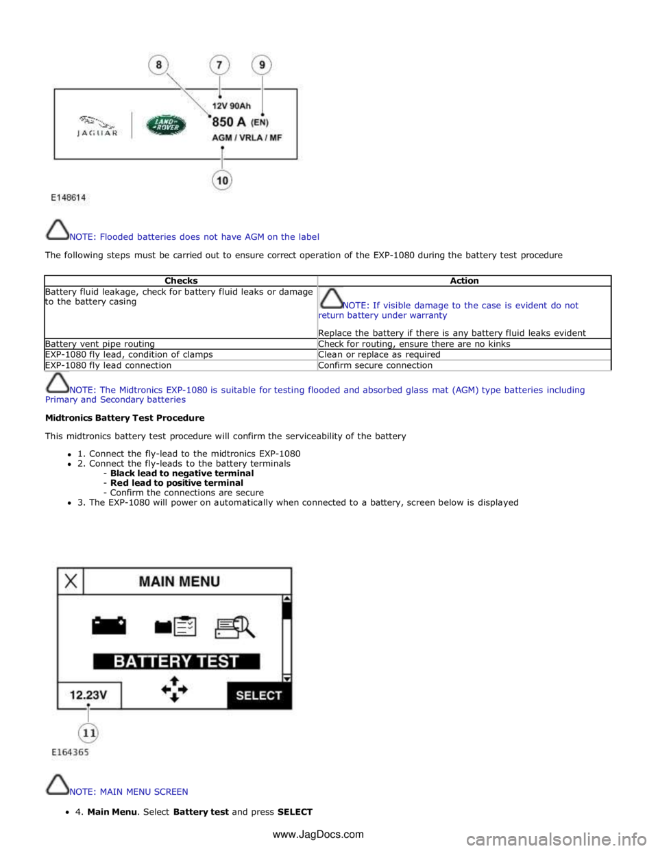
NOTE: Flooded batteries does not have AGM on the label
The following steps must be carried out to ensure correct operation of the EXP-1080 during the battery test procedure
Checks Action Battery fluid leakage, check for battery fluid leaks or damage
to the battery casing
NOTE: If visible damage to the case is evident do not
return battery under warranty
Replace the battery if there is any battery fluid leaks evident Battery vent pipe routing Check for routing, ensure there are no kinks EXP-1080 fly lead, condition of clamps Clean or replace as required EXP-1080 fly lead connection Confirm secure connection
NOTE: The Midtronics EXP-1080 is suitable for testing flooded and absorbed glass mat (AGM) type batteries including
Primary and Secondary batteries
Midtronics Battery Test Procedure
This midtronics battery test procedure will confirm the serviceability of the battery
1. Connect the fly-lead to the midtronics EXP-1080
2. Connect the fly-leads to the battery terminals
- Black lead to negative terminal
- Red lead to positive terminal
- Confirm the connections are secure
3. The EXP-1080 will power on automatically when connected to a battery, screen below is displayed
NOTE: MAIN MENU SCREEN 4.MainMenu.SelectBatterytestandpressSELECT
www.JagDocs.com
Page 1896 of 3039
NOTE:
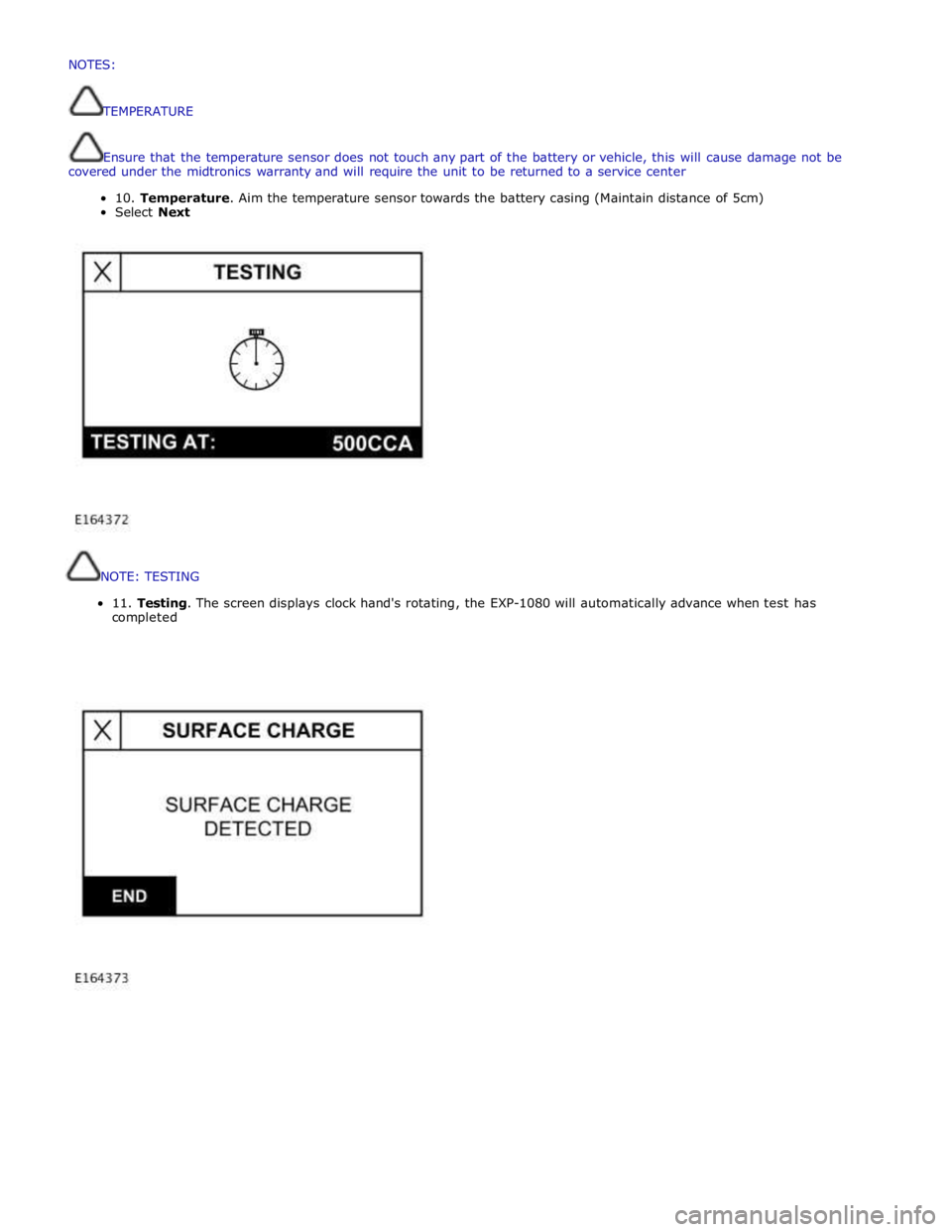
TESTING
11.
Testing.
The
screen
displays
clock
hand's
rotating,
the
EXP-1080
will
automatically
advance
when
test
has
completed
NOTES:
TEMPERATURE
Ensurethatthetemperaturesensordoesnottouchanypartofthebatteryorvehicle,thiswillcausedamagenotbe
coveredunderthemidtronicswarrantyand willrequiretheunittobereturnedtoaservicecenter
10.Temperature.Aimthetemperaturesensortowardsthebatterycasing (Maintaindistanceof5cm)
SelectNext
Page 1899 of 3039
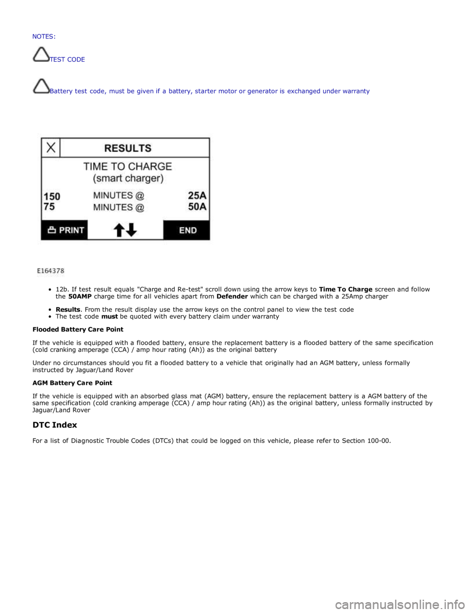
Battery
test
code,
must
be
given if
a
battery,
starter
motor
or
generator
is
exchanged
under
warranty
12b.
If
test
result
equals
"Charge
and
Re-test"
scroll
down
using
the
arrow
keys
to
Time To
Charge
screen and follow
the
50AMP
charge
time
for
all
vehicles
apart
from
Defender
which
can
be
charged
with a
25Amp
charger
Results.
From
the
result
display
use
the
arrow
keys
on
the
control
panel
to
view the
test
code
The
test
code
must
be
quoted
with every
battery
claim
under
warranty
Flooded
Battery
Care
Point
If
the
vehicle
is
equipped with
a
flooded
battery,
ensure
the
replacement
battery
is
a
flooded
battery
of
the
same
specification
(cold
cranking
amperage
(CCA)
/ amp
hour
rating
(Ah))
as
the
original
battery
Under
no
circumstances
should you
fit
a
flooded
battery
to a
vehicle
that
originally
had
an
AGM
battery,
unless
formally
instructed
by Jaguar/Land
Rover
AGM
Battery
Care
Point
If
the
vehicle
is
equipped with
an absorbed
glass
mat
(AGM)
battery,
ensure
the
replacement
battery
is
a
AGM
battery
of
the
same
specification
(cold
cranking
amperage
(CCA)
/
amp
hour
rating
(Ah))
as
the
original
battery,
unless
formally
instructed
by
Jaguar/Land
Rover
DTC
Index
For
a
list
of
Diagnostic
Trouble
Codes
(DTCs)
that
could
be
logged
on
this
vehicle,
please
refer
to
Section
100-00. NOTES:
TESTCODE
Page 1912 of 3039
transmits the calculated voltage to the generator and regulator on the LIN bus connection.
The ECM will over-ride the voltage value requested by the battery monitoring system if it detects a fault in the generator and regulator. The ECM also signals the instrument cluster to display a warning message if it detects a fault with the generator and regulator. For additionalinformation refer to Instrument Cluster 413-01.
GENERATOR AND REGULATOR Component Description
The regulator provides a controlled variable voltage output from the generator. Two electrical terminals are provided on the
outer casing of the generator. One terminal supplies the DC (direct current) voltage output from the generator to the battery
positive terminal. The second terminal provides the LIN bus connection between the regulator and the ECM. www.JagDocs.com
Page 1929 of 3039
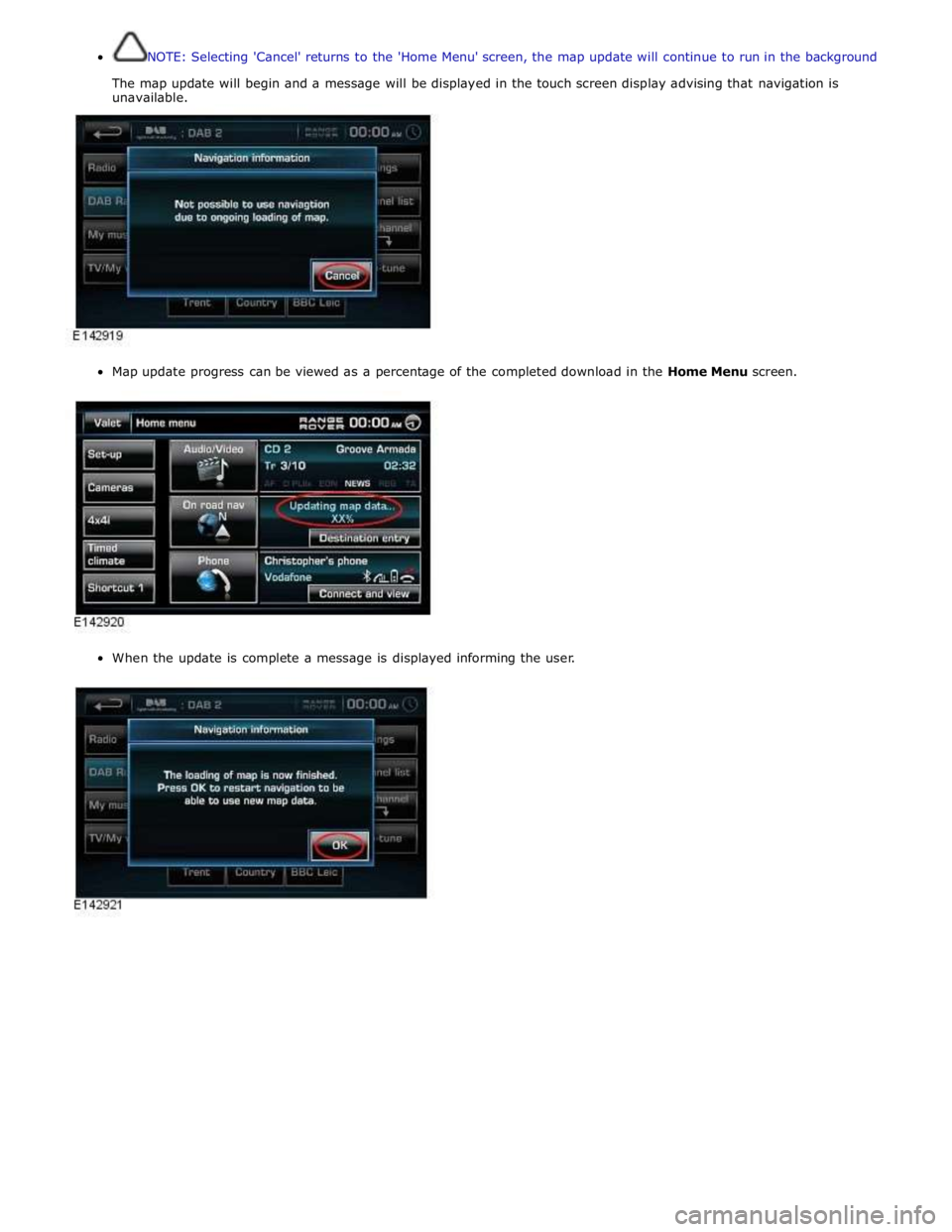
NOTE: Selecting 'Cancel' returns to the 'Home Menu' screen, the map update will continue to run in the background
The map update will begin and a message will be displayed in the touch screen display advising that navigation is
unavailable.
Map update progress can be viewed as a percentage of the completed download in the Home Menu screen.
When the update is complete a message is displayed informing the user.