2010 JAGUAR XFR display
[x] Cancel search: displayPage 2010 of 3039
Published: 23-Jan-2012
Information and Entertainment System - DTC: Audio Input Control Module - Audio Input Control Module
Diagnosis and Testing
Principle of Operation
This section of the manual concerns diagnostic procedures for the Dension audio input control module. For a detailed
description of the information and entertainment system, refer to the relevant description and operation sections in the
workshop manual
Inspection and Verification
CAUTION: Diagnosis by substitution from a donor vehicle is NOT acceptable. Substitution of control modules does not
guarantee confirmation of a fault, and may also cause additional faults in the vehicle being tested and/or the donor vehicle
1. Verify the customer concern
2. Visually inspect for obvious signs of damage and system integrity
Visual Inspection
Mechanical Electrical
Audio input control module
Audio amplifier module
Integrated audio module
Integrated control panel
Touch screen display
Loudspeakers
Fuses
Loose or corroded connector(s)
Audio amplifier module
Integrated audio module
Integrated control panel
Touch screen display
Loudspeakers
3. If an obvious cause for an observed or reported concern is found, correct the cause (if possible) before proceeding to
the next step
4. If the cause is not visually evident, check for diagnostic trouble codes and refer to the relevant diagnostic trouble codes
index
Audio Input Control Module Diagnostics
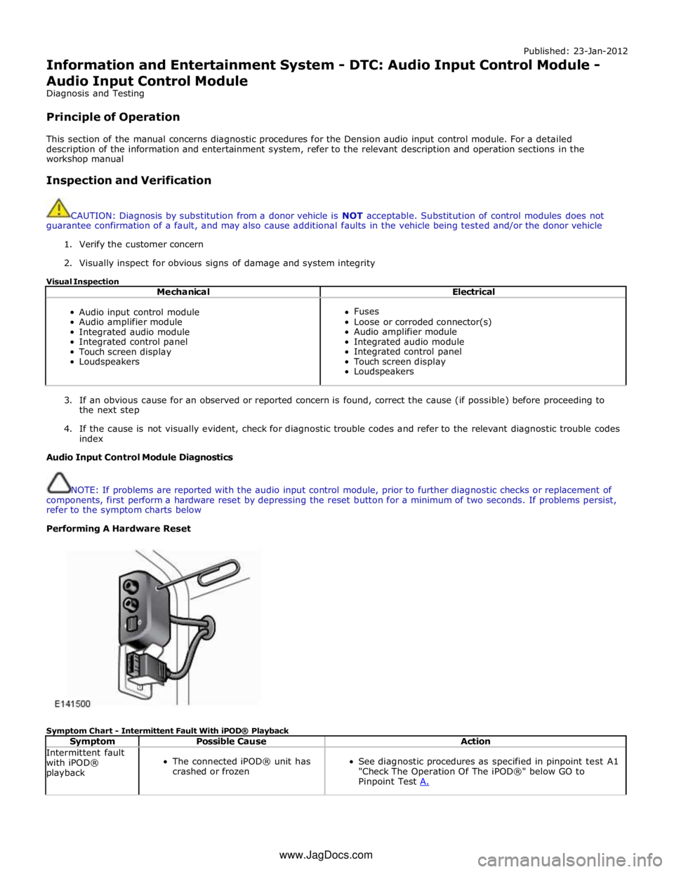
NOTE: If problems are reported with the audio input control module, prior to further diagnostic checks or replacement of
components, first perform a hardware reset by depressing the reset button for a minimum of two seconds. If problems persist,
refer to the symptom charts below
Performing A Hardware Reset
Symptom Chart - Intermittent Fault With iPOD® Playback
Symptom Possible Cause Action Intermittent fault
with iPOD®
playback
The connected iPOD® unit has
crashed or frozen
See diagnostic procedures as specified in pinpoint test A1
"Check The Operation Of The iPOD®" below GO to
Pinpoint Test A. www.JagDocs.com
Page 2012 of 3039
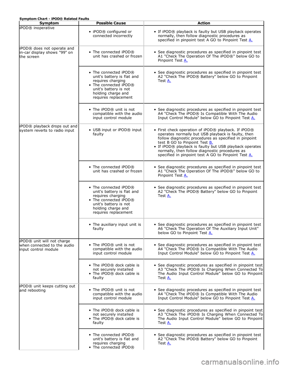
Symptom Chart - iPOD® Related Faults
Symptom Possible Cause Action iPOD® inoperative
iPOD® configured or
connected incorrectly
If iPOD® playback is faulty but USB playback operates
normally, then follow diagnostic procedures as
specified in pinpoint test A GO to Pinpoint Test A. iPOD® does not operate and
in-car display shows "99" on
the screen
The connected iPOD®
unit has crashed or frozen
See diagnostic procedures as specified in pinpoint test
A1 "Check The Operation Of The iPOD®" below GO to
Pinpoint Test A.
The connected iPOD®
unit's battery is flat and
requires charging
The connected iPOD®
unit's battery is not
holding charge and
requires replacement
See diagnostic procedures as specified in pinpoint test
A2 "Check The iPOD® Battery" below GO to Pinpoint
Test A.
The iPOD® unit is not
compatible with the audio
input control module
See diagnostic procedures as specified in pinpoint test
A4 "Check The iPOD® Is Compatible With The Audio
Input Control Module" below GO to Pinpoint Test A. iPOD® playback drops out and
system reverts to radio input
USB input or iPOD® input
faulty
First check operation of iPOD® playback. If iPOD®
operates normally but USB playback is faulty, then
follow diagnostic procedures as specified in pinpoint
test B GO to Pinpoint Test B. If iPOD® playback is faulty but USB playback operates
normally, then follow diagnostic procedures as
specified in pinpoint test A GO to Pinpoint Test A.
The connected iPOD®
unit has crashed or frozen
See diagnostic procedures as specified in pinpoint test
A1 "Check The Operation Of The iPOD®" below GO to
Pinpoint Test A.
The connected iPOD®
unit's battery is flat and
requires charging
The connected iPOD®
unit's battery is not
holding charge and
requires replacement
See diagnostic procedures as specified in pinpoint test
A2 "Check The iPOD® Battery" below GO to Pinpoint
Test A.
The auxiliary input unit is
faulty
See diagnostic procedures as specified in pinpoint test
A6 "Check The Operation Of The Auxiliary Input Unit"
below GO to Pinpoint Test A. iPOD® unit will not charge
when connected to the audio
input control module
The iPOD® unit is not
compatible with the audio
input control module
See diagnostic procedures as specified in pinpoint test
A4 "Check The iPOD® Is Compatible With The Audio
Input Control Module" below GO to Pinpoint Test A.
The iPOD® dock cable is
not securely installed
The iPOD® dock cable is
faulty
See diagnostic procedures as specified in pinpoint test
A3 "Check The iPOD® Is Charging When Connected To
The Audio Input Control Module" below GO to Pinpoint
Test A. iPOD® unit keeps cutting out
and rebooting
The iPOD® unit is not
compatible with the audio
input control module
See diagnostic procedures as specified in pinpoint test
A4 "Check The iPOD® Is Compatible With The Audio
Input Control Module" below GO to Pinpoint Test A.
The iPOD® dock cable is
not securely installed
The iPOD® dock cable is
faulty
See diagnostic procedures as specified in pinpoint test
A3 "Check The iPOD® Is Charging When Connected To
The Audio Input Control Module" below GO to Pinpoint
Test A.
The connected iPOD®
unit's battery is flat and
requires charging
The connected iPOD®
See diagnostic procedures as specified in pinpoint test
A2 "Check The iPOD® Battery" below GO to Pinpoint
Test A.
Page 2013 of 3039
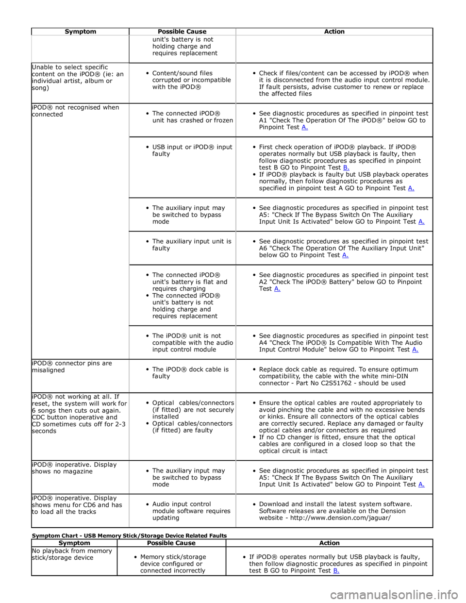
Symptom Possible Cause Action unit's battery is not
holding charge and
requires replacement Unable to select specific
content on the iPOD® (ie: an
individual artist, album or
song)
Content/sound files
corrupted or incompatible
with the iPOD®
Check if files/content can be accessed by iPOD® when
it is disconnected from the audio input control module.
If fault persists, advise customer to renew or replace
the affected files iPOD® not recognised when
connected
The connected iPOD®
unit has crashed or frozen
See diagnostic procedures as specified in pinpoint test
A1 "Check The Operation Of The iPOD®" below GO to
Pinpoint Test A.
USB input or iPOD® input
faulty
First check operation of iPOD® playback. If iPOD®
operates normally but USB playback is faulty, then
follow diagnostic procedures as specified in pinpoint
test B GO to Pinpoint Test B. If iPOD® playback is faulty but USB playback operates
normally, then follow diagnostic procedures as
specified in pinpoint test A GO to Pinpoint Test A.
The auxiliary input may
be switched to bypass
mode
See diagnostic procedures as specified in pinpoint test
A5: "Check If The Bypass Switch On The Auxiliary
Input Unit Is Activated" below GO to Pinpoint Test A.
The auxiliary input unit is
faulty
See diagnostic procedures as specified in pinpoint test
A6 "Check The Operation Of The Auxiliary Input Unit"
below GO to Pinpoint Test A.
The connected iPOD®
unit's battery is flat and
requires charging
The connected iPOD®
unit's battery is not
holding charge and
requires replacement
See diagnostic procedures as specified in pinpoint test
A2 "Check The iPOD® Battery" below GO to Pinpoint
Test A.
The iPOD® unit is not
compatible with the audio
input control module
See diagnostic procedures as specified in pinpoint test
A4 "Check The iPOD® Is Compatible With The Audio
Input Control Module" below GO to Pinpoint Test A. iPOD® connector pins are
misaligned
The iPOD® dock cable is
faulty
Replace dock cable as required. To ensure optimum
compatibility, the cable with the white mini-DIN
connector - Part No C2S51762 - should be used iPOD® not working at all. If
reset, the system will work for
6 songs then cuts out again.
CDC button inoperative and
CD sometimes cuts off for 2-3
seconds
Optical cables/connectors
(if fitted) are not securely
installed
Optical cables/connectors
(if fitted) are faulty
Ensure the optical cables are routed appropriately to
avoid pinching the cable and with no excessive bends
or kinks. Ensure all connectors of the optical cables
are correctly secured. Replace any damaged or faulty
optical cables and/or connectors as required
If no CD changer is fitted, ensure that the optical
cables are configured in a closed loop so that the
optical circuit is intact iPOD® inoperative. Display
shows no magazine
The auxiliary input may
be switched to bypass
mode
See diagnostic procedures as specified in pinpoint test
A5: "Check If The Bypass Switch On The Auxiliary
Input Unit Is Activated" below GO to Pinpoint Test A. iPOD® inoperative. Display
shows menu for CD6 and has
to load all the tracks
Audio input control
module software requires
updating
Download and install the latest system software.
Software releases are available on the Dension
website - http://www.dension.com/jaguar/ Symptom Chart - USB Memory Stick/Storage Device Related Faults
Symptom Possible Cause Action No playback from memory
stick/storage device
Memory stick/storage
device configured or
connected incorrectly
If iPOD® operates normally but USB playback is faulty,
then follow diagnostic procedures as specified in pinpoint
test B GO to Pinpoint Test B.
Page 2027 of 3039
by Field Effect Transistors (FET's). The FET's can detect overloads and short circuits and respond to heat generated by
increased current flow caused by a short circuit.
On a normal conventionally protected circuit this would cause a fuse to blow. The FET's respond to the heat increase and
disconnect the power supply to the affected circuit. When the fault is rectified or the FET has cooled, the FET will reset and
operate the circuit normally. If the fault persists the FET will cycle, disconnecting and reconnecting the power supply.
The CJB and the RJB store fault codes which can be retrieved using a Jaguar approved diagnostic system. The fault code will identify that there is a fault on a particular output circuit which will assist with fault diagnosis and detection.
Alarm Indications
The exterior lighting system is used for alarm arm and disarm requests to show alarm system status.
When the driver locks and arms the vehicle, a visual indication of a successful lock and arm request is displayed to the driver
by a single flash of the hazard flashers. If the vehicle is superlocked, then the hazard flashers will flash a second time (200 ms
off and 200 ms on) to confirm the superlock request.
If the alarm is activated, the hazard flashers are operated for 10, 30 second cycles of 200 ms on and 200 ms off, with a 10
second delay between each cycle.
NOTE: On North American Specification (NAS) vehicles, the delay between the cycle when the alarm is activated is 60
seconds.
Lights on Warning
When the ignition is in the off power mode 0 or accessory power mode 4 and the lighting control switch is in the side lamp or
headlamp position, a warning chime will sound if the driver's door is opened. This indicates to the driver that the exterior
lights have been left switched on.
The chime is generated from the instrument cluster sounder on receipt of a lights on signal, a driver's door open signal and an
ignition off power mode 0 or accessory power mode 4 signal via a medium speed CAN bus signal from the CJB. Headlamp Timer
The RJB controls the headlamp timer function which allows the headlamps to remain on for a period of time after leaving the vehicle. This is a driver convenience feature which illuminates the driveway after leaving the vehicle.
To operate the timer function the lighting control switch must be in one of the three headlamp timer positions when the
ignition status is changed from ignition on power mode 6 to the off power mode 0. The timer function will then be initiated and
the low beam headlamps will be illuminated for the selected timer period.
NOTE: If the lighting switch is in the AUTO position, the headlamp timer will not function when the ignition is changed to
off power mode 0.
When the lighting control switch is in the autolamp exit delay position, the lighting control switch reference voltage flows
through 4 of the resistors. The returned signal voltage is detected by the instrument cluster which outputs a message on the
medium speed CAN bus to the RJB that autolamps has been selected.
Depending on the selected exit delay position, the reference voltage to the autolamp exit delay switch is routed through 3, 2
or 1 resistors which is detected by the instrument cluster. The cluster outputs a message on the medium speed CAN bus to the RJB that autolamp exit delay period has been selected at 30, 60 or 120 seconds respectively. Crash Signal Activation
When a crash signal is transmitted from the RCM (restraints control module), the RJB activates the hazard flashers. The hazard flashers continue to operate until the ignition is in the off power mode 0 or accessory power mode 6. Once this ignition state
has occurred, the RCM will cease to transmit the crash signal.
LIGHTING CONTROL SWITCH
The instrument cluster outputs 2 reference voltages to the rotary lighting control switch; one feed being supplied to the light
selection function of the switch and the second feed being supplied to the auto headlamp exit delay function. The switch
position is determined by instrument cluster by the change in returned signal voltage which is routed through up to 4 resistors
in series depending on the selection made.
OFF - When the lighting control switch is in the off position, the reference voltage flows through 1 of the resistors. The
returned signal voltage is detected by the instrument cluster which outputs a message on the medium speed CAN bus to the CJB that no lighting selection is made. The reference voltage to the auto headlamp exit delay switch is routed through 4 resistors which is detected by the instrument cluster which outputs a message on the medium speed CAN bus to the CJB that auto headlamp or exit delay has not been selected.
SIDE LAMPS - When the lighting control switch is in the side lamp position, the reference voltage flows through 2 of the
resistors. The returned signal voltage is detected by the instrument cluster which outputs a message on the medium speed
CAN bus to the CJB to activate the side lamps. The reference voltage to the autolamp exit delay switch is routed through 4 resistors which is detected by the instrument cluster which outputs a message on the medium speed CAN bus to the CJB that auto headlamp or exit delay has not been selected.
HEADLAMPS - When the lighting control switch is in the headlamp position, the reference voltage flows through 3 of the
Page 2073 of 3039
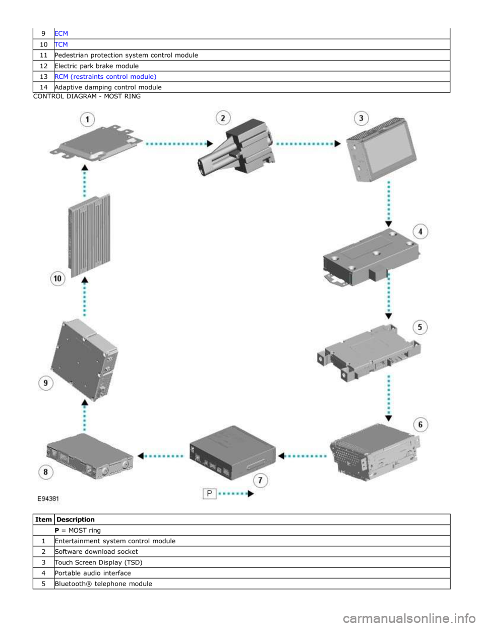
10 TCM 11 Pedestrian protection system control module 12 Electric park brake module 13 RCM (restraints control module) 14 Adaptive damping control module CONTROL DIAGRAM - MOST RING
Item Description P = MOST ring 1 Entertainment system control module 2 Software download socket 3 Touch Screen Display (TSD) 4 Portable audio interface 5 Bluetooth® telephone module
Page 2075 of 3039
Module Communications Network - Communications Network
Diagnosis and Testing
Principles of Operation Published: 25-Nov-2013
For a detailed description of the Communications Network, refer to the relevant Description and Operation sections in the
workshop manual. REFER to: (418-00 Module Communications Network)
Communications Network (Description and Operation),
Communications Network (Description and Operation), Communications Network (Description and Operation).
Inspection and Verification
CAUTIONS:
Diagnosis by substitution from a donor vehicle is NOT acceptable. Substitution of control modules does not guarantee
confirmation of a fault, and may also cause additional faults in the vehicle being tested and/or the donor vehicle.
Electronic modules are sensitive to static electrical charges. If exposed to these charges, damage may result.
1. Verify the customer concern
2. Visually inspect for obvious signs of damage and system integrity
3. If an obvious cause for an observed or reported concern is found, correct the cause (if possible) before proceeding to
the next step
4. If the cause is not visually evident, check for Diagnostic Trouble Codes (DTCs) and refer to the DTC Index
Symptom Chart
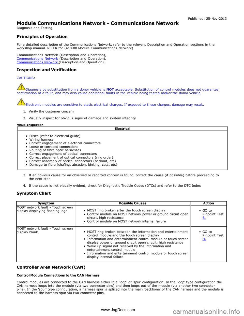
Symptom Possible Causes Action MOST network fault - Touch screen
display displaying flashing logo
MOST ring broken after the touch screen display
Control module on MOST network power or ground circuit open
circuit, high resistance
Control module on MOST network internal failure
GO to
Pinpoint Test
B. MOST network fault - Touch screen
display blank
MOST ring broken between the information and entertainment
control module and the touch screen display
Information and entertainment control module or touch screen
display power or ground circuit open circuit, high resistance
Wake up signal not received by the information and
entertainment control module
Information and entertainment control module or touch screen
display internal failure
GO to
Pinpoint Test
H. Controller Area Network (CAN)
Control Module Connections to the CAN Harness
Control modules are connected to the CAN harness either in a 'loop' or 'spur' configuration. In the 'loop' type configuration the
CAN harness loops into the module (via two connector pins) and then loops out of the module (via another two connector
pins). In the 'spur' type configuration, a harness spur is spliced into the main 'backbone' of the CAN harness and the module is
connected to the harness spur via two connector pins. Electrical
Fuses (refer to electrical guide)
Wiring harness
Correct engagement of electrical connectors
Loose or corroded connections
Routing of fibre optic harnesses
Correct engagement of optical connectors
Correct placement of optical connectors (ring order)
Correct assembly of optical connectors (backout, etc)
Damage to fibre (chafing, abrasion, kinking, cuts, etc) Visual Inspection
www.JagDocs.com
Page 2076 of 3039

CAN Harness Architecture
For a detailed description of the CAN Networks and architecture, refer to the relevant Description and Operation section in the
Workshop Manual.
CAN Network Integrity Tests
If a control module is suspected of non-communication, the Network Integrity test application available on the manufacturer
approved diagnostic system can be used to confirm if communication is possible between the control modules on the vehicle
and the manufacturer approved diagnostic system (via the J1962 diagnostic connector ). The results from the test can be used
to determine if either a single module or multiple modules are failing to communicate.
CAN Terminating Modules
If the Network Integrity test indicates that one or more module on one of the CAN networks (HS or MS) are failing to
communicate, there are several checks that can be made. The first step is to identify if both of the CAN terminating modules
on each individual CAN Bus are communicating. If both CAN terminating modules for each individual CAN Bus are
communicating (identified via the Network Integrity test), then it can be confirmed that the main 'backbone' of the CAN
harness is complete. The main 'backbone' of the CAN harness consists of all the modules connected to the CAN harness via a
'loop' configuration and also includes the two terminating modules.
Communication with both CAN terminating modules via the Network Integrity test confirms the physical integrity of the main
'backbone' of the CAN harness (and the harness spur to the J1962 diagnostic connector). This means that there is no
requirement to check the resistance of the CAN Network. This is because the standard check for 60 ohms across the CAN High
and CAN Low lines will not provide any additional information regarding the physical condition of the CAN harness, beyond
what has already been determined from the Network Integrity test.
Non-Communication of a Terminating Module
If a Network Integrity test reveals a terminating module is failing to communicate it can indicate a break in the main
'backbone' of the CAN harness. The first checks should always be to confirm the power and ground supplies to the
non-communicating module are correct. Providing these are correct, the resistance between the CAN High and CAN Low lines at
the J1962 connector can be checked to determine the integrity of the main 'backbone' of the CAN harness. After disconnecting
the battery a reading of 120 ohms would indicate an open circuit in the main 'backbone' of the CAN harness. Alternatively, a
reading of 60 ohms would indicate that there is no open circuit fault with the main 'backbone' of the CAN harness.
It is worth noting that even if one of the terminating modules is disconnected from the CAN harness, communications between
the modules still connected may still be possible. Therefore communication between the manufacturer approved diagnostic
system and the connected modules may also be possible.
Locating CAN Harness Open Circuits
In the case where multiple modules, including a terminating module, are failing to communicate, having first confirmed the
power and ground supplies are correct, the approximate location of the open circuit can be identified from analysis of the
Network Integrity test results and reference to the relevant CAN network circuit diagrams. For example, if an open circuit
existed in a certain position on the CAN harness, any module positioned on the Network between the J1962 connector and the
open circuit should return a response during the Network Integrity test. No responses would be returned from any modules
past the open circuit fault in the Network.
CAN Harness 'Spur' Type Configuration Circuits
If, after the initial checks (Network Integrity test using the manufacturer approved diagnostic system, and power and ground
supplies to the module have been checked and confirmed as correct), a module that is connected to the CAN harness via a
'spur' type configuration is suspected of not communicating, then the physical integrity of the CAN harness 'spur' can be
checked.
This is most easily undertaken by individually checking the continuity of the CAN High and CAN Low lines between the
non-communicating module connector (with the module disconnected) and the J1962 diagnostic connector.
'Lost Communications' DTCs
As well as the methods described so far in this document, which can be used to determine the location of an open circuit in
the CAN harness, 'Lost Communications' DTCs can also be used for this purpose. Lost communication DTCs mean that a
module is not receiving CAN information from another module.
For example, if a global DTC read were to be carried out, only DTCs stored in the modules that the manufacturer approved
diagnostic system could communicate with would be displayed. If there was an open circuit fault in a certain position on the
CAN harness, the modules that could display DTCs would all be prior to the open circuit on the Network, and these modules
should display 'Lost Communications' DTCs with all the modules located on the Network past the open circuit fault.
'Bus off' DTCs
The references to bus and its condition refer to the network concerned and the modules on that network.
If a module logs a 'Bus Off' DTC, it means that the module has detected CAN transmission errors and has disabled it's own
CAN transmissions and disconnected itself from the network in an attempt to allow the rest of the network to function. At this
point the 'Bus Off' DTC is set. A common cause of 'Bus Off' DTCs can be a short circuit in the CAN network.
Page 2077 of 3039
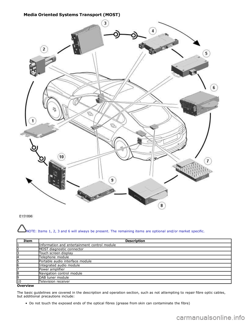
NOTE: Items 1, 2, 3 and 6 will always be present. The remaining items are optional and/or market specific.
Item Description 1 Information and entertainment control module 2 MOST diagnostic connector 3 Touch screen display 4 Telephone module 5 Portable audio interface module 6 Integrated audio module 7 Power amplifier 8 Navigation control module 9 DAB tuner module 10 Television receiver Overview
The basic guidelines are covered in the description and operation section, such as not attempting to repair fibre optic cables,
but additional precautions include:
Do not touch the exposed ends of the optical fibres (grease from skin can contaminate the fibre) Media Oriented Systems Transport (MOST)