2010 JAGUAR XFR display
[x] Cancel search: displayPage 1842 of 3039

Parking Aid - Parking Aid - Overview
Description and Operation
OVERVIEW Published: 11-May-2011
The parking aid system provides an audible warning to the driver when any obstacles are in the path of the vehicle during a
forward (if front sensors are fitted) or reversing manoeuver. The purpose of the system is to assist the driver when parking or
manoeuvring in a restricted space. It is not designed as a crash avoidance system or a replacement for visual interpretation by
the driver.
All vehicles are fitted with rear parking aid sensors. Higher specification vehicles may also be fitted with front parking aid
sensors.
A roof console mounted parking aid switch allows the driver to deactivate the parking aid system if operation is not required.
NOTE: The switch is only fitted to vehicles with front parking aid sensors.
A parking aid camera is a standard fitment on some models and optional on others. The parking aid camera supplements the
information provided by the parking aid system by providing the driver with a visual display of the area directly behind the
vehicle.
www.JagDocs.com
Page 1845 of 3039
3 RJB 4 Entertainment system control module 5 Touch Screen Display (TSD) 6 Parking aid camera
PARKING AID System Operation
Two levels of parking aid system can be fitted; a rear only system or a front and rear system.
The parking aid module receives and ignition power mode 6 supply from the RJB. The parking aid module is connected to the entertainment system control module by the medium speed CAN (controller area
network) bus and the Media Orientated System Transport (MOST). The entertainment system is used by the parking aid system
to provide the driver with an audible warning. If an obstacle is sensed by the rear parking aid sensors, the rear audio system
speakers will sound. If an obstacle is sensed by the front parking aid sensors (if fitted), the front audio system speakers will
sound.
The parking aid system operates using ultrasonic signals which are transmitted by the sensors. The reflected echo from this
output is received by the sensors and used by the parking aid module to calculate the distance from an object.
When the parking aid module activates the system, the switch LED (light emitting diode) is illuminated to indicate that the
system is operating. The parking aid module then processes signals received from the sensors to determine if there is an
object with the detection range of the sensors. A parking aid screen is automatically displayed in the Touch Screen Display. If
the vehicle has a parking aid camera fitted, the camera display is automatically displayed in the TSD in preference to the
parking aid alert display. To view the parking aid sensor display, a single touch of the TSD screen will remove the camera
image display and show the parking aid alert display.
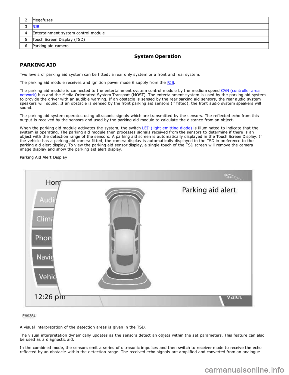
Parking Aid Alert Display
A visual interpretation of the detection areas is given in the TSD.
The visual interpretation dynamically updates as the sensors detect an objets within the set parameters. This feature can also
be used as a diagnostic aid.
In the combined mode, the sensors emit a series of ultrasonic impulses and then switch to receiver mode to receive the echo
reflected by an obstacle within the detection range. The received echo signals are amplified and converted from an analogue
Page 1847 of 3039
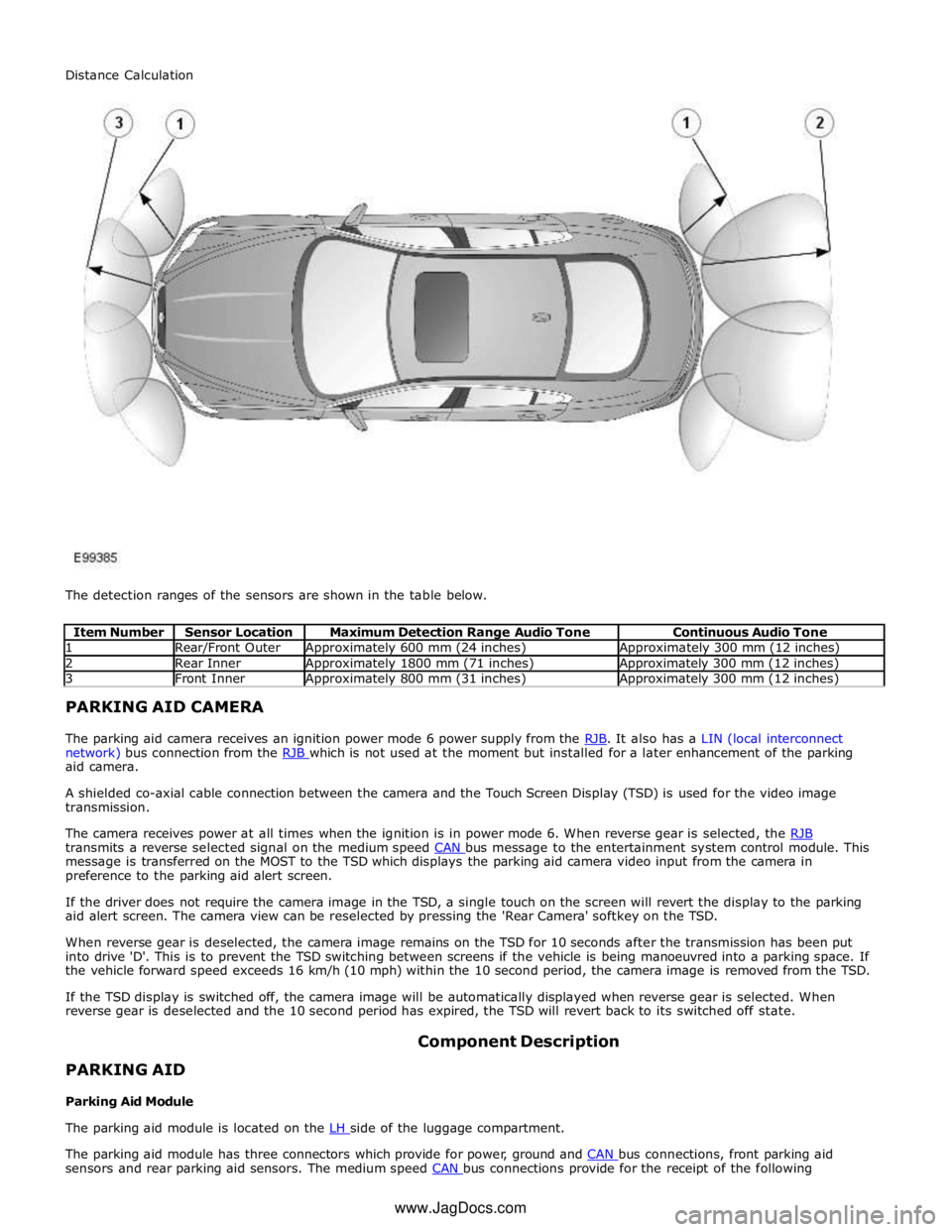
1 Rear/Front Outer Approximately 600 mm (24 inches) Approximately 300 mm (12 inches) 2 Rear Inner Approximately 1800 mm (71 inches) Approximately 300 mm (12 inches) 3 Front Inner Approximately 800 mm (31 inches) Approximately 300 mm (12 inches) PARKING AID CAMERA
The parking aid camera receives an ignition power mode 6 power supply from the RJB. It also has a LIN (local interconnect network) bus connection from the RJB which is not used at the moment but installed for a later enhancement of the parking aid camera.
A shielded co-axial cable connection between the camera and the Touch Screen Display (TSD) is used for the video image
transmission.
The camera receives power at all times when the ignition is in power mode 6. When reverse gear is selected, the RJB transmits a reverse selected signal on the medium speed CAN bus message to the entertainment system control module. This message is transferred on the MOST to the TSD which displays the parking aid camera video input from the camera in
preference to the parking aid alert screen.
If the driver does not require the camera image in the TSD, a single touch on the screen will revert the display to the parking
aid alert screen. The camera view can be reselected by pressing the 'Rear Camera' softkey on the TSD.
When reverse gear is deselected, the camera image remains on the TSD for 10 seconds after the transmission has been put
into drive 'D'. This is to prevent the TSD switching between screens if the vehicle is being manoeuvred into a parking space. If
the vehicle forward speed exceeds 16 km/h (10 mph) within the 10 second period, the camera image is removed from the TSD.
If the TSD display is switched off, the camera image will be automatically displayed when reverse gear is selected. When
reverse gear is deselected and the 10 second period has expired, the TSD will revert back to its switched off state.
PARKING AID
Parking Aid Module Component Description
The parking aid module is located on the LH side of the luggage compartment.
The parking aid module has three connectors which provide for power, ground and CAN bus connections, front parking aid sensors and rear parking aid sensors. The medium speed CAN bus connections provide for the receipt of the following Distance Calculation
www.JagDocs.com
Page 1849 of 3039
PARKING AID CAMERA
The parking aid camera receives an ignition power mode 6 power supply from the RJB. It also has a LIN bus connection with the RJB, which is used as a gateway. A shielded co-axial cable connection between the camera and the TSD is used for the video image transmission.
The camera receives power at all times when the ignition is in power mode 6. When reverse gear is selected, the RJB transmits a reverse selected message on the medium speed CAN bus. The information and entertainment module transfers the message on the MOST ring to the TSD, which displays the video input from the parking aid camera in preference to the parking
aid alert screen.
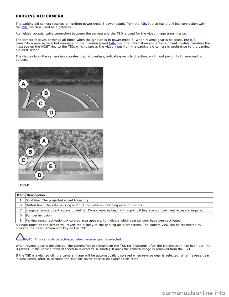
The display from the camera incorporates graphic overlays, indicating vehicle direction, width and proximity to surrounding
objects.
Item Description A Solid line: The projected wheel trajectory B Dotted line: The safe working width of the vehicle (including exterior mirrors) C Luggage compartment access guideline: Do not reverse beyond this point if luggage compartment access is required D Bumper inclusion E Parking sensor activation: A colored area appears, to indicate which rear sensors have been activated A single touch on the screen will revert the display to the parking aid alert screen. The camera view can be reselected by
pressing the Rear Camera soft key on the TSD.
NOTE: This can only be activated when reverse gear is selected.
When reverse gear is deselected, the camera image remains on the TSD for 2 seconds after the transmission has been put into
D (drive). If the vehicle forward speed in D exceeds 16 km/h (10 mph) the camera image is removed from the TSD.
If the TSD is switched off, the camera image will be automatically displayed when reverse gear is selected. When reverse gear
is deselected, after 10 seconds the TSD will revert back to its switched off state.
Page 1851 of 3039
Mechanical Electrical Parking aid control module
Parking aid sounder
Audio system
4. If an obvious cause for an observed or reported concern is found, correct the cause (if possible) before proceeding to
the next step
5. If the cause is not visually evident, check for diagnostic trouble codes (DTCs) and refer to the DTC index
Symptom Chart
CAUTION: Do not apply any grease based products to any parking aid system connector or pins
NOTES:
Please note if this diagnosis is being carried out on a vehicle without a hard wired parking aid speaker, ensure the in car
infotainment system is fully functional and configured correctly
Parking aid sensors that are painted incorrectly and not to the manufacturer standards, will not be considered in any
warranty claim
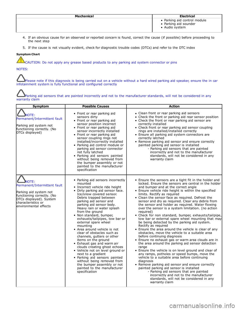
Symptom Possible Causes Action
NOTE:
Permanent/Intermittent fault
Parking aid system not
functioning correctly. (No
DTCs displayed)
Front or rear parking aid
sensors dirty
Front or rear parking aid
sensor position incorrect
Front or rear parking aid
sensor incorrectly installed
Front or rear parking aid
sensor coupling rings not
installed/incorrectly installed
Parking aid control module or
parking aid sensor connector
not fully latched
Parking aid sensors painted
without being removed from
the bumper assembly or not
painted to the manufacturer
specification
Clean front or rear parking aid sensors
Check the front or parking aid rear sensor position
Check the front or rear parking aid sensor are
correctly installed
Check front or rear parking aid sensor coupling
rings are installed/installed correctly
Ensure all parking aid system connectors are
correctly latched
Remove parking aid sensor and ensure correctly
painted parking aid sensor is installed
- Parking aid sensors that are painted
incorrectly and not to the manufacturer
standards, will not be considered in any
warranty claim
NOTE:
Permanent/Intermittent fault
Parking aid system not
functioning correctly. (No
DTCs displayed). System
characteristics or
environmental effects
Parking aid sensors incorrectly
mounted
Incorrect vehicle ride height
Dirty parking aid sensor face.
Ice/snow covered sensor.
Debris trapped between
parking aid sensor and
parking aid sensor body.
Heavy rain or water splash
from the ground
Non standard, bumper,
exhausts/tailpipes, tow bar or
external spare wheel
mounting
Area around vehicle is not
clear of obstacles such as
channels, gutters or other
items on the ground
Exhaust gas and warm air
clouds creating ghost echoes
Vehicle not on level ground or
next to a gradient
Parking aid sensors painted
without being removed from
the bumper assembly or not
painted to the manufacturer
specification
Ensure the sensors are a tight fit in the holder and
locked. Ensure the sensors are central in the holder
and bumper and at the correct angle
Ensure vehicle ride height is within the specified
limits. Rectify as required
Clean the sensor face as required. Defrost the
sensor and dry as required. Clear any debris from
the sensor and holder as required. Water flowing
over the sensor is a system limitation. (no action
required)
Check for non standard, bumper, exhausts/tailpipe,
tow bar or external spare wheel mounting that may
be being detected by the parking aid system.
Rectify as required
Ensure the area around the vehicle is clear of any
obstacles, move the vehicle to a suitable area
before continuing diagnosis
Ensure no exhaust gas or warm area clouds are in
the area around the parking aid sensor detection
range
Ensure the vehicle is on level ground and clear of
any ramps, potholes or speed bumps, move the
vehicle to a suitable area before continuing
diagnosis
Remove parking aid sensor and ensure correctly
painted parking aid sensor is installed
- Parking aid sensors that are painted
incorrectly and not to the manufacturer
standards, will not be considered in any
warranty claim
Page 1856 of 3039
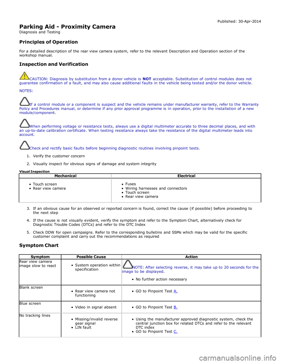
Parking Aid - Proximity Camera
Diagnosis and Testing
Principles of Operation Published: 30-Apr-2014
For a detailed description of the rear view camera system, refer to the relevant Description and Operation section of the
workshop manual.
Inspection and Verification
CAUTION: Diagnosis by substitution from a donor vehicle is NOT acceptable. Substitution of control modules does not
guarantee confirmation of a fault, and may also cause additional faults in the vehicle being tested and/or the donor vehicle.
NOTES:
If a control module or a component is suspect and the vehicle remains under manufacturer warranty, refer to the Warranty
Policy and Procedures manual, or determine if any prior approval programme is in operation, prior to the installation of a new
module/component.
When performing voltage or resistance tests, always use a digital multimeter accurate to three decimal places, and with
an up-to-date calibration certificate. When testing resistance always take the resistance of the digital multimeter leads into
account.
Check and rectify basic faults before beginning diagnostic routines involving pinpoint tests.
1. Verify the customer concern
2. Visually inspect for obvious signs of damage and system integrity
Visual Inspection
Mechanical Electrical
Touch screen
Rear view camera
Fuses
Wiring harnesses and connectors
Touch screen
Rear view camera
3. If an obvious cause for an observed or reported concern is found, correct the cause (if possible) before proceeding to
the next step
4. If the cause is not visually evident, verify the symptom and refer to the Symptom Chart, alternatively check for
Diagnostic Trouble Codes (DTCs) and refer to the DTC Index
5. Check DDW for open campaigns. Refer to the corresponding bulletins and SSMs which may be valid for the specific
customer complaint and carry out the recommendations as required
Symptom Chart
Symptom Possible Cause Action Rear view camera
image slow to react
System operation within
specification
NOTE: After selecting reverse, it may take up to 20 seconds for the
image to be displayed.
No further action necessary Blank screen
Rear view camera not
functioning
GO to Pinpoint Test A. Blue screen
Video in signal absent
GO to Pinpoint Test B. No tracking lines
Missing/invalid reverse
gear signal
LIN fault
Using the manufacturer approved diagnostic system, check the
central junction box for related DTCs and refer to the relevant
DTC index
GO to Pinpoint Test C.
Page 1857 of 3039
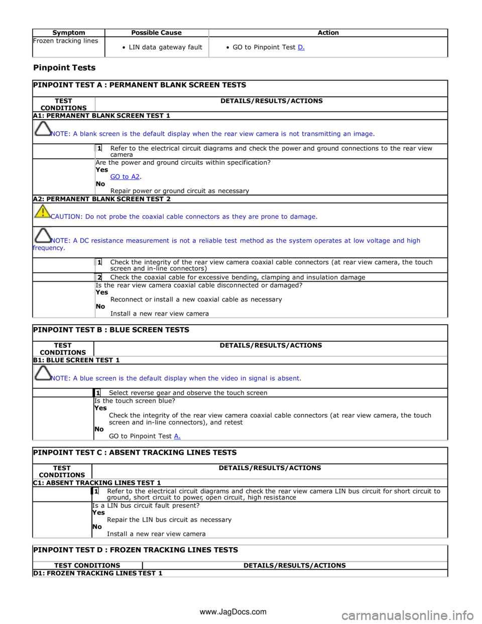
Symptom Possible Cause Action Frozen tracking lines
LIN data gateway fault
GO to Pinpoint Test D. Pinpoint Tests
PINPOINT TEST A : PERMANENT BLANK SCREEN TESTS TEST
CONDITIONS DETAILS/RESULTS/ACTIONS A1: PERMANENT BLANK SCREEN TEST 1
NOTE: A blank screen is the default display when the rear view camera is not transmitting an image. 1 Refer to the electrical circuit diagrams and check the power and ground connections to the rear view camera Are the power and ground circuits within specification? Yes
GO to A2. No
Repair power or ground circuit as necessary A2: PERMANENT BLANK SCREEN TEST 2
CAUTION: Do not probe the coaxial cable connectors as they are prone to damage.
NOTE: A DC resistance measurement is not a reliable test method as the system operates at low voltage and high
frequency. 1 Check the integrity of the rear view camera coaxial cable connectors (at rear view camera, the touch screen and in-line connectors) 2 Check the coaxial cable for excessive bending, clamping and insulation damage Is the rear view camera coaxial cable disconnected or damaged? Yes
Reconnect or install a new coaxial cable as necessary
No
Install a new rear view camera
PINPOINT TEST B : BLUE SCREEN TESTS TEST
CONDITIONS DETAILS/RESULTS/ACTIONS B1: BLUE SCREEN TEST 1
NOTE: A blue screen is the default display when the video in signal is absent. 1 Select reverse gear and observe the touch screen Is the touch screen blue?
Yes
Check the integrity of the rear view camera coaxial cable connectors (at rear view camera, the touch
screen and in-line connectors), and retest
No
GO to Pinpoint Test A.
PINPOINT TEST C : ABSENT TRACKING LINES TESTS TEST
CONDITIONS DETAILS/RESULTS/ACTIONS C1: ABSENT TRACKING LINES TEST 1 1 Refer to the electrical circuit diagrams and check the rear view camera LIN bus circuit for short circuit to ground, short circuit to power, open circuit, high resistance Is a LIN bus circuit fault present? Yes
Repair the LIN bus circuit as necessary
No
Install a new rear view camera
PINPOINT TEST D : FROZEN TRACKING LINES TESTS TEST CONDITIONS DETAILS/RESULTS/ACTIONS D1: FROZEN TRACKING LINES TEST 1 www.JagDocs.com
Page 1869 of 3039
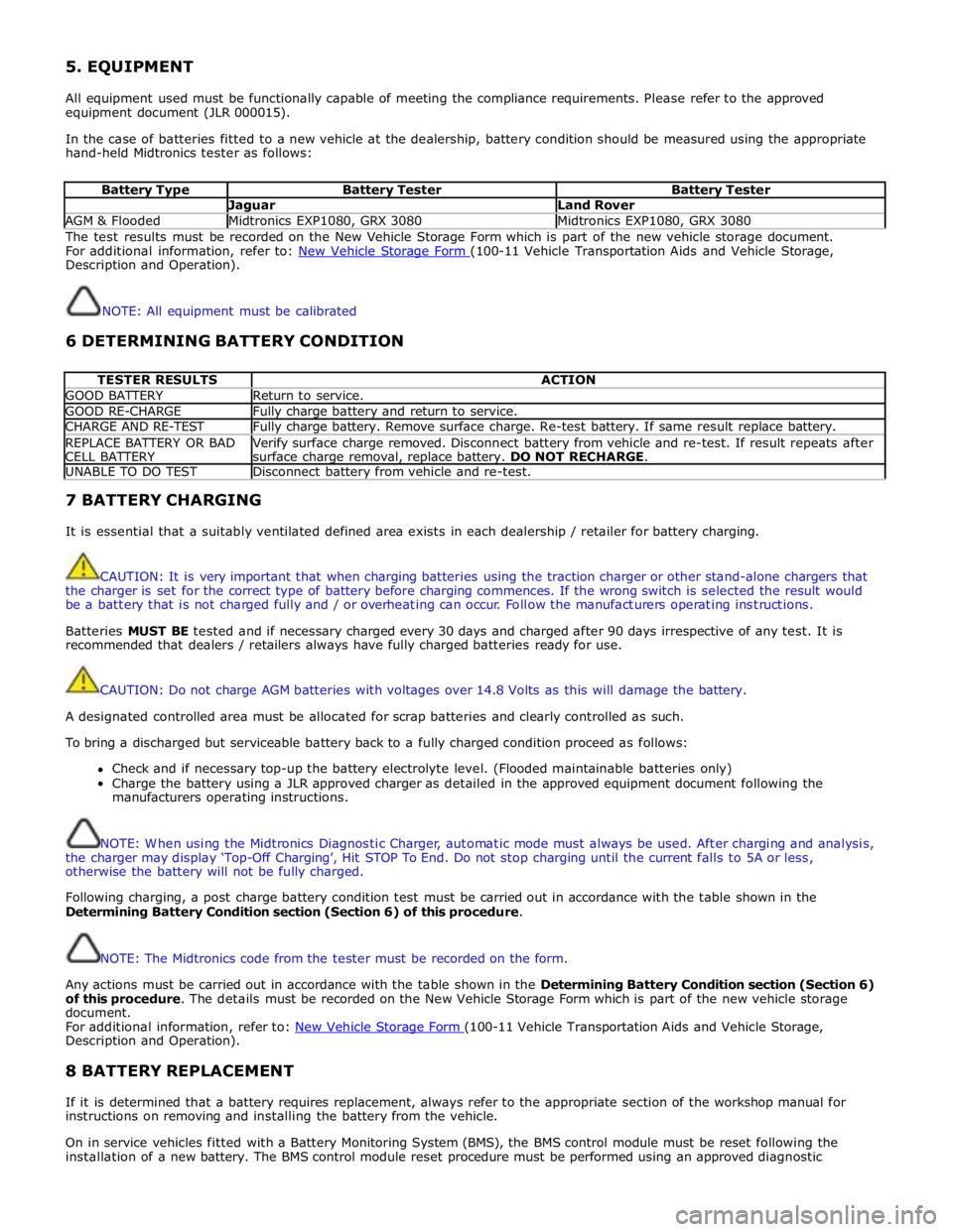
5. EQUIPMENT
All equipment used must be functionally capable of meeting the compliance requirements. Please refer to the approved
equipment document (JLR 000015).
In the case of batteries fitted to a new vehicle at the dealership, battery condition should be measured using the appropriate
hand-held Midtronics tester as follows:
Battery Type Battery Tester Battery Tester Jaguar Land Rover AGM & Flooded Midtronics EXP1080, GRX 3080 Midtronics EXP1080, GRX 3080 The test results must be recorded on the New Vehicle Storage Form which is part of the new vehicle storage document.
For additional information, refer to: New Vehicle Storage Form (100-11 Vehicle Transportation Aids and Vehicle Storage, Description and Operation).
NOTE: All equipment must be calibrated
6 DETERMINING BATTERY CONDITION
TESTER RESULTS ACTION GOOD BATTERY Return to service. GOOD RE-CHARGE Fully charge battery and return to service. CHARGE AND RE-TEST Fully charge battery. Remove surface charge. Re-test battery. If same result replace battery. REPLACE BATTERY OR BAD
CELL BATTERY Verify surface charge removed. Disconnect battery from vehicle and re-test. If result repeats after
surface charge removal, replace battery. DO NOT RECHARGE. UNABLE TO DO TEST Disconnect battery from vehicle and re-test. 7 BATTERY CHARGING
It is essential that a suitably ventilated defined area exists in each dealership / retailer for battery charging.
CAUTION: It is very important that when charging batteries using the traction charger or other stand-alone chargers that
the charger is set for the correct type of battery before charging commences. If the wrong switch is selected the result would
be a battery that is not charged fully and / or overheating can occur. Follow the manufacturers operating instructions.
Batteries MUST BE tested and if necessary charged every 30 days and charged after 90 days irrespective of any test. It is
recommended that dealers / retailers always have fully charged batteries ready for use.
CAUTION: Do not charge AGM batteries with voltages over 14.8 Volts as this will damage the battery.
A designated controlled area must be allocated for scrap batteries and clearly controlled as such.
To bring a discharged but serviceable battery back to a fully charged condition proceed as follows:
Check and if necessary top-up the battery electrolyte level. (Flooded maintainable batteries only)
Charge the battery using a JLR approved charger as detailed in the approved equipment document following the
manufacturers operating instructions.
NOTE: When using the Midtronics Diagnostic Charger, automatic mode must always be used. After charging and analysis,
the charger may display ‘Top-Off Charging’, Hit STOP To End. Do not stop charging until the current falls to 5A or less,
otherwise the battery will not be fully charged.
Following charging, a post charge battery condition test must be carried out in accordance with the table shown in the
Determining Battery Condition section (Section 6) of this procedure.
NOTE: The Midtronics code from the tester must be recorded on the form.
Any actions must be carried out in accordance with the table shown in the Determining Battery Condition section (Section 6)
of this procedure. The details must be recorded on the New Vehicle Storage Form which is part of the new vehicle storage
document.
For additional information, refer to: New Vehicle Storage Form (100-11 Vehicle Transportation Aids and Vehicle Storage, Description and Operation).
8 BATTERY REPLACEMENT
If it is determined that a battery requires replacement, always refer to the appropriate section of the workshop manual for
instructions on removing and installing the battery from the vehicle.
On in service vehicles fitted with a Battery Monitoring System (BMS), the BMS control module must be reset following the
installation of a new battery. The BMS control module reset procedure must be performed using an approved diagnostic