2010 JAGUAR XFR display
[x] Cancel search: displayPage 2078 of 3039
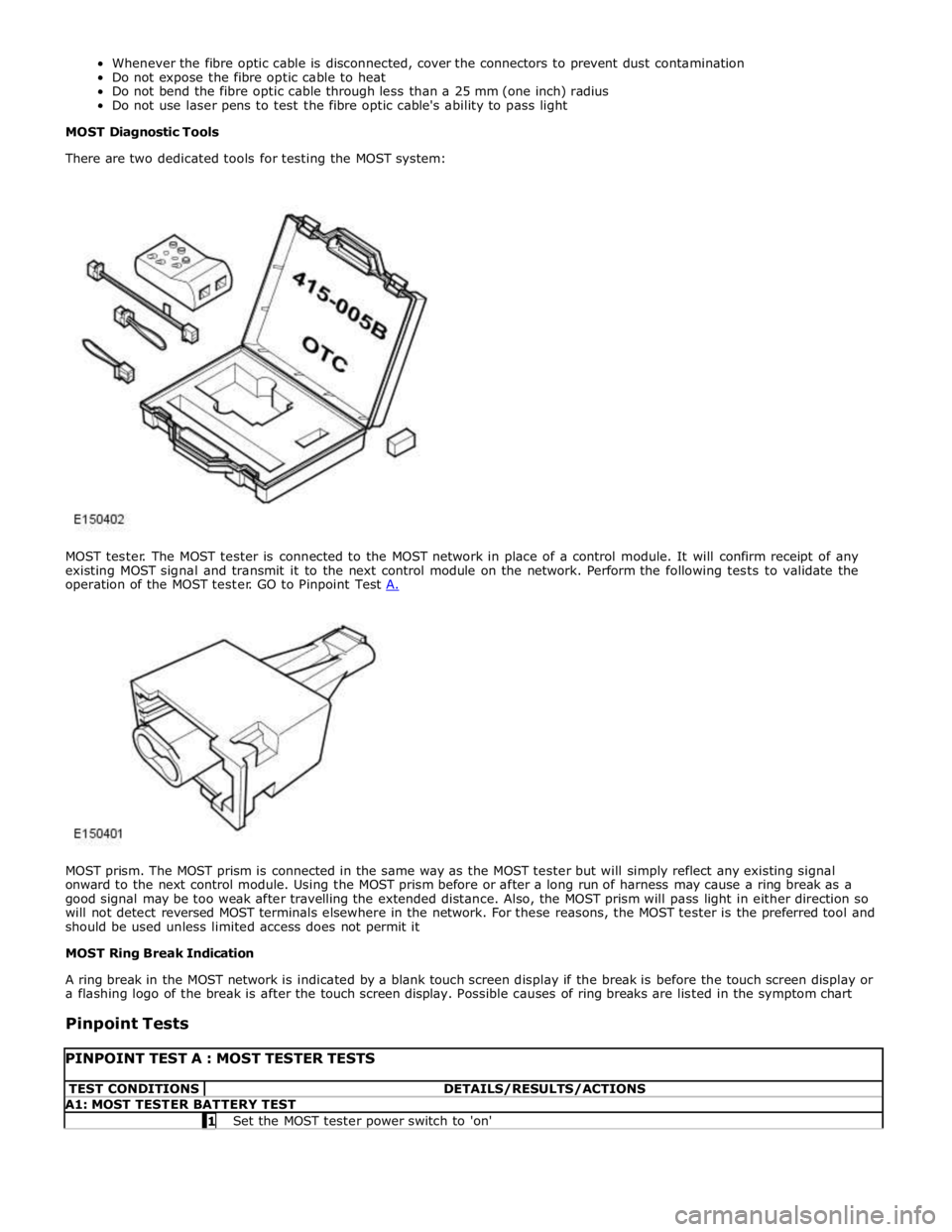
MOST prism. The MOST prism is connected in the same way as the MOST tester but will simply reflect any existing signal
onward to the next control module. Using the MOST prism before or after a long run of harness may cause a ring break as a
good signal may be too weak after travelling the extended distance. Also, the MOST prism will pass light in either direction so
will not detect reversed MOST terminals elsewhere in the network. For these reasons, the MOST tester is the preferred tool and
should be used unless limited access does not permit it
MOST Ring Break Indication
A ring break in the MOST network is indicated by a blank touch screen display if the break is before the touch screen display or
a flashing logo of the break is after the touch screen display. Possible causes of ring breaks are listed in the symptom chart
Pinpoint Tests
PINPOINT TEST A : MOST TESTER TESTS TEST CONDITIONS DETAILS/RESULTS/ACTIONS A1: MOST TESTER BATTERY TEST 1 Set the MOST tester power switch to 'on'
Page 2080 of 3039
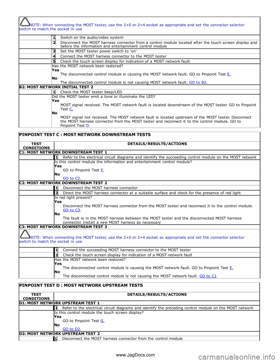
NOTE: When connecting the MOST tester, use the 2+0 or 2+4 socket as appropriate and set the connector selector
switch to match the socket in use 1 Switch on the audio/video system 2 Disconnect the MOST harness connector from a control module located after the touch screen display and before the information and entertainment control module 3 Set the MOST tester power switch to 'on' 4 Connect the MOST harness connector to the MOST tester 5 Check the touch screen display for indication of a MOST network fault Has the MOST network been restored? Yes
The disconnected control module is causing the MOST network fault. GO to Pinpoint Test E. No
The disconnected control module is not causing MOST network fault. GO to B2. B2: MOST NETWORK INITIAL TEST 2 1 Check the MOST tester beep/LED Did the MOST tester emit a tone or illuminate the LED? Yes
MOST signal received. The MOST network fault is located downstream of the MOST tester. GO to Pinpoint
Test C. No
MOST signal not received. The MOST network fault is located upstream of the MOST tester. Disconnect
the MOST harness connector from the MOST tester and reconnect it to the control module. GO to Pinpoint Test D.
PINPOINT TEST C : MOST NETWORK DOWNSTREAM TESTS TEST
CONDITIONS DETAILS/RESULTS/ACTIONS C1: MOST NETWORK DOWNSTREAM TEST 1 1 Refer to the electrical circuit diagrams and identify the succeeding control module on the MOST network Is this control module the information and entertainment control module?
Yes
GO to Pinpoint Test F. No
GO to C2. C2: MOST NETWORK DOWNSTREAM TEST 2 1 Disconnect the MOST harness connector 2 Direct the MOST harness connector at a suitable surface and check for the presence of red light Is red light present?
Yes
Disconnect the MOST harness connector from the MOST tester and reconnect it to the control module.
GO to C3. No
The fault is in the MOST harness between the MOST tester and the disconnected MOST harness
connector. Install a new MOST harness as necessary C3: MOST NETWORK DOWNSTREAM TEST 3
NOTE: When connecting the MOST tester, use the 2+0 or 2+4 socket as appropriate and set the connector selector
switch to match the socket in use 1 Connect the succeeding MOST harness connector to the MOST tester 2 Check the touch screen display for indication of a MOST network fault Has the MOST network been restored?
Yes
The disconnected control module is causing the MOST network fault. GO to Pinpoint Test E. No
The disconnected control module is not causing the MOST network fault. GO to C1.
PINPOINT TEST D : MOST NETWORK UPSTREAM TESTS TEST
CONDITIONS DETAILS/RESULTS/ACTIONS D1: MOST NETWORK UPSTREAM TEST 1 1 Refer to the electrical circuit diagrams and identify the preceding control module on the MOST network Is this control module the touch screen display?
Yes
GO to Pinpoint Test G. No
GO to D2. D2: MOST NETWORK UPSTREAM TEST 2 1 Disconnect the MOST harness connector from the control module www.JagDocs.com
Page 2081 of 3039
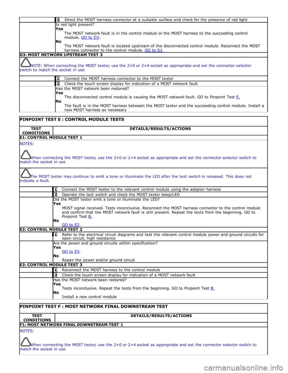
2 Direct the MOST harness connector at a suitable surface and check for the presence of red light Is red light present?
Yes
The MOST network fault is in the control module or the MOST harness to the succeeding control
module. GO to D3. No
The MOST network fault is located upstream of the disconnected control module. Reconnect the MOST
harness connector to the control module. GO to D1. D3: MOST NETWORK UPSTREAM TEST 3
NOTE: When connecting the MOST tester, use the 2+0 or 2+4 socket as appropriate and set the connector selector
switch to match the socket in use 1 Connect the MOST harness connector to the MOST tester 2 Check the touch screen display for indication of a MOST network fault Has the MOST network been restored?
Yes
The disconnected control module is causing the MOST network fault. GO to Pinpoint Test E. No
The fault is in the MOST harness between the MOST tester and the succeeding control module. Install a
new MOST harness as necessary
PINPOINT TEST E : CONTROL MODULE TESTS TEST
CONDITIONS DETAILS/RESULTS/ACTIONS E1: CONTROL MODULE TEST 1 NOTES:
When connecting the MOST tester, use the 2+0 or 2+4 socket as appropriate and set the connector selector switch to
match the socket in use
The MOST tester may continue to emit a tone or illuminate the LED after the test switch is released. This does not
indicate a fault. 1 Connect the MOST tester to the relevant control module using the adapter harness 2 Operate the test switch and check the MOST tester beep/LED Did the MOST tester emit a tone or illuminate the LED? Yes
MOST signal received. Tests inconclusive. Reconnect the MOST harness connector to the control module
and confirm that the MOST network fault is still present. Repeat the tests from the beginning. GO to
Pinpoint Test B. No
GO to E2. E2: CONTROL MODULE TEST 2 1 Refer to the electrical circuit diagrams and test the relevant control module power and ground circuits for open circuit, high resistance Are the power and ground circuits within specification? Yes
GO to E3. No
Repair the power and/or ground circuit E3: CONTROL MODULE TEST 3 1 Reconnect the MOST harness to the control module 2 Check the touch screen display for indication of a MOST network fault Has the MOST network been restored? Yes
Tests inconclusive. Repeat the tests from the beginning. GO to Pinpoint Test B. No
Install a new control module
PINPOINT TEST F : MOST NETWORK FINAL DOWNSTREAM TEST TEST
CONDITIONS DETAILS/RESULTS/ACTIONS F1: MOST NETWORK FINAL DOWNSTREAM TEST 1 NOTES:
When connecting the MOST tester, use the 2+0 or 2+4 socket as appropriate and set the connector selector switch to
match the socket in use
Page 2082 of 3039
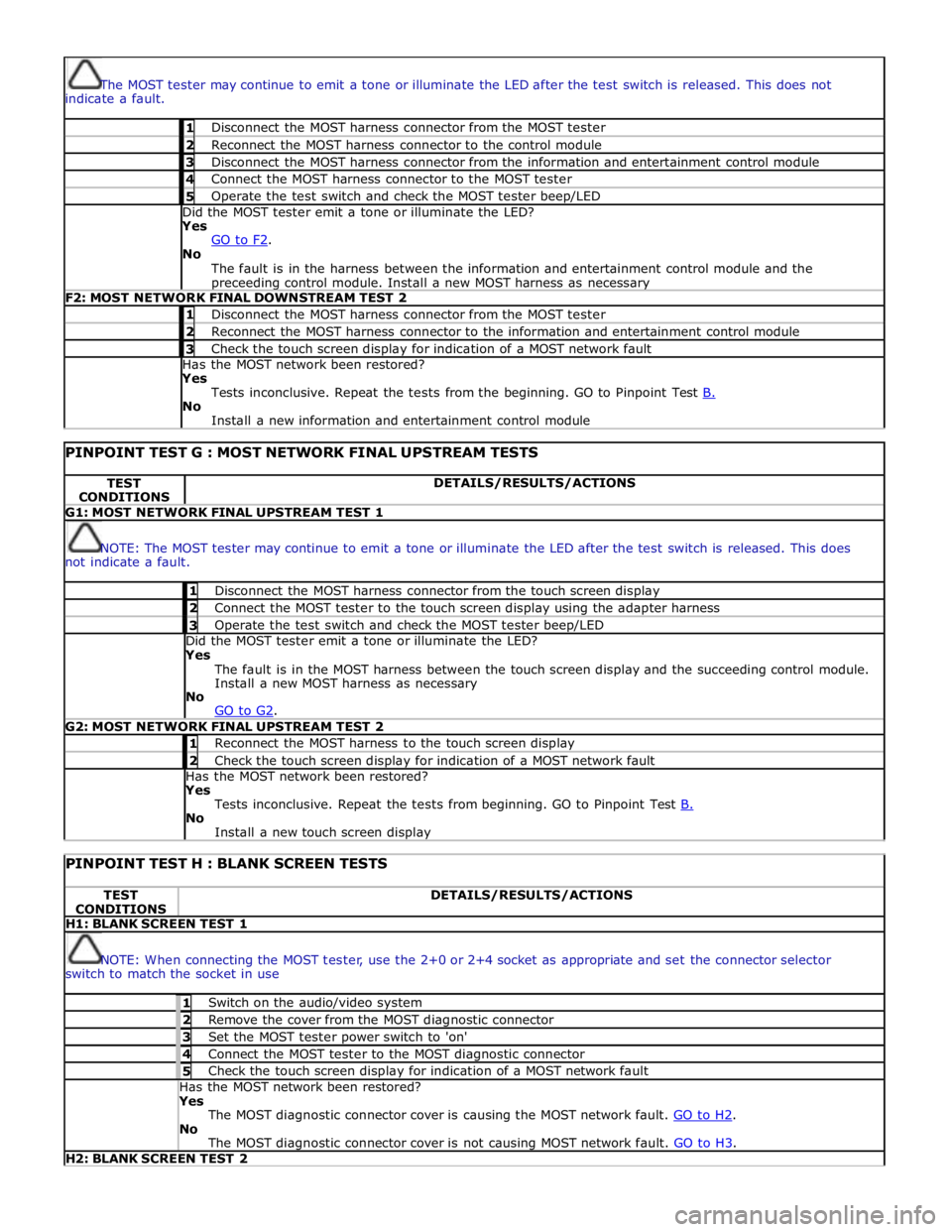
The MOST tester may continue to emit a tone or illuminate the LED after the test switch is released. This does not
indicate a fault. 1 Disconnect the MOST harness connector from the MOST tester 2 Reconnect the MOST harness connector to the control module 3 Disconnect the MOST harness connector from the information and entertainment control module 4 Connect the MOST harness connector to the MOST tester 5 Operate the test switch and check the MOST tester beep/LED Did the MOST tester emit a tone or illuminate the LED? Yes
GO to F2. No
The fault is in the harness between the information and entertainment control module and the preceeding control module. Install a new MOST harness as necessary F2: MOST NETWORK FINAL DOWNSTREAM TEST 2 1 Disconnect the MOST harness connector from the MOST tester 2 Reconnect the MOST harness connector to the information and entertainment control module 3 Check the touch screen display for indication of a MOST network fault Has the MOST network been restored? Yes
Tests inconclusive. Repeat the tests from the beginning. GO to Pinpoint Test B. No
Install a new information and entertainment control module
PINPOINT TEST G : MOST NETWORK FINAL UPSTREAM TESTS TEST
CONDITIONS DETAILS/RESULTS/ACTIONS G1: MOST NETWORK FINAL UPSTREAM TEST 1
NOTE: The MOST tester may continue to emit a tone or illuminate the LED after the test switch is released. This does
not indicate a fault. 1 Disconnect the MOST harness connector from the touch screen display 2 Connect the MOST tester to the touch screen display using the adapter harness 3 Operate the test switch and check the MOST tester beep/LED Did the MOST tester emit a tone or illuminate the LED? Yes
The fault is in the MOST harness between the touch screen display and the succeeding control module.
Install a new MOST harness as necessary
No
GO to G2. G2: MOST NETWORK FINAL UPSTREAM TEST 2 1 Reconnect the MOST harness to the touch screen display 2 Check the touch screen display for indication of a MOST network fault Has the MOST network been restored? Yes
Tests inconclusive. Repeat the tests from beginning. GO to Pinpoint Test B. No
Install a new touch screen display
PINPOINT TEST H : BLANK SCREEN TESTS TEST
CONDITIONS DETAILS/RESULTS/ACTIONS H1: BLANK SCREEN TEST 1
NOTE: When connecting the MOST tester, use the 2+0 or 2+4 socket as appropriate and set the connector selector
switch to match the socket in use 1 Switch on the audio/video system 2 Remove the cover from the MOST diagnostic connector 3 Set the MOST tester power switch to 'on' 4 Connect the MOST tester to the MOST diagnostic connector 5 Check the touch screen display for indication of a MOST network fault Has the MOST network been restored? Yes
The MOST diagnostic connector cover is causing the MOST network fault. GO to H2. No
The MOST diagnostic connector cover is not causing MOST network fault. GO to H3. H2: BLANK SCREEN TEST 2
Page 2083 of 3039
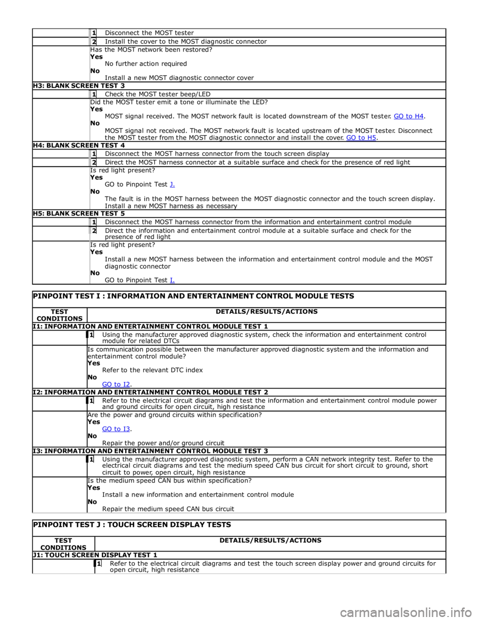
1 Disconnect the MOST tester 2 Install the cover to the MOST diagnostic connector Has the MOST network been restored? Yes
No further action required
No
Install a new MOST diagnostic connector cover H3: BLANK SCREEN TEST 3 1 Check the MOST tester beep/LED Did the MOST tester emit a tone or illuminate the LED? Yes
MOST signal received. The MOST network fault is located downstream of the MOST tester. GO to H4. No
MOST signal not received. The MOST network fault is located upstream of the MOST tester. Disconnect
the MOST tester from the MOST diagnostic connector and install the cover. GO to H5. H4: BLANK SCREEN TEST 4 1 Disconnect the MOST harness connector from the touch screen display 2 Direct the MOST harness connector at a suitable surface and check for the presence of red light Is red light present? Yes
GO to Pinpoint Test J. No
The fault is in the MOST harness between the MOST diagnostic connector and the touch screen display.
Install a new MOST harness as necessary H5: BLANK SCREEN TEST 5 1 Disconnect the MOST harness connector from the information and entertainment control module 2 Direct the information and entertainment control module at a suitable surface and check for the presence of red light Is red light present? Yes
Install a new MOST harness between the information and entertainment control module and the MOST
diagnostic connector
No
GO to Pinpoint Test I.
PINPOINT TEST I : INFORMATION AND ENTERTAINMENT CONTROL MODULE TESTS TEST
CONDITIONS DETAILS/RESULTS/ACTIONS I1: INFORMATION AND ENTERTAINMENT CONTROL MODULE TEST 1 1 Using the manufacturer approved diagnostic system, check the information and entertainment control module for related DTCs Is communication possible between the manufacturer approved diagnostic system and the information and
entertainment control module? Yes
Refer to the relevant DTC index
No
GO to I2. I2: INFORMATION AND ENTERTAINMENT CONTROL MODULE TEST 2 1 Refer to the electrical circuit diagrams and test the information and entertainment control module power and ground circuits for open circuit, high resistance Are the power and ground circuits within specification? Yes
GO to I3. No
Repair the power and/or ground circuit I3: INFORMATION AND ENTERTAINMENT CONTROL MODULE TEST 3 1 Using the manufacturer approved diagnostic system, perform a CAN network integrity test. Refer to the electrical circuit diagrams and test the medium speed CAN bus circuit for short circuit to ground, short
circuit to power, open circuit, high resistance Is the medium speed CAN bus within specification? Yes
Install a new information and entertainment control module
No
Repair the medium speed CAN bus circuit
PINPOINT TEST J : TOUCH SCREEN DISPLAY TESTS TEST
CONDITIONS DETAILS/RESULTS/ACTIONS J1: TOUCH SCREEN DISPLAY TEST 1 1 Refer to the electrical circuit diagrams and test the touch screen display power and ground circuits for open circuit, high resistance
Page 2084 of 3039
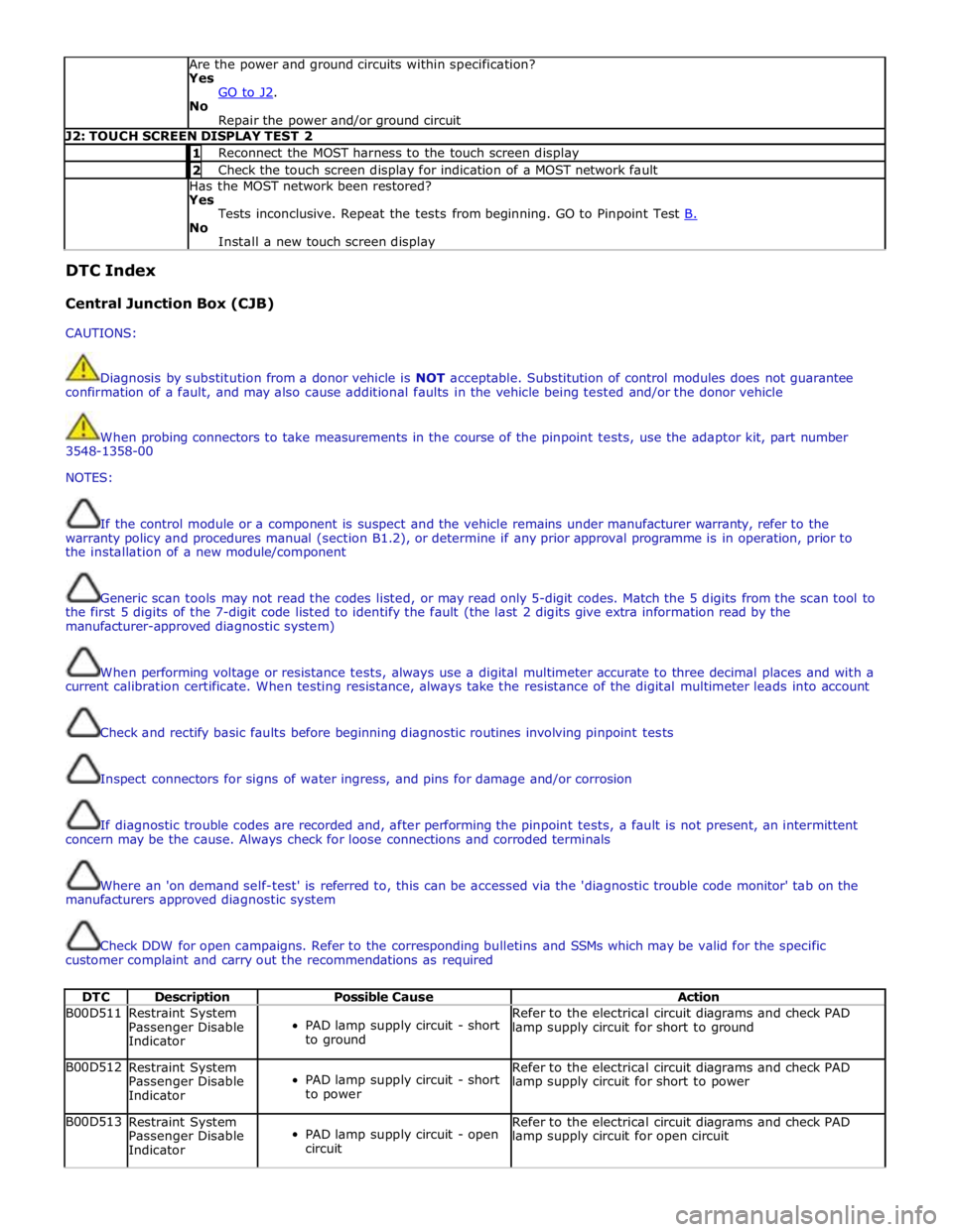
Are the power and ground circuits within specification?
Yes
GO to J2. No
Repair the power and/or ground circuit J2: TOUCH SCREEN DISPLAY TEST 2 1 Reconnect the MOST harness to the touch screen display 2 Check the touch screen display for indication of a MOST network fault Has the MOST network been restored?
Yes
Tests inconclusive. Repeat the tests from beginning. GO to Pinpoint Test B. No
Install a new touch screen display DTC Index
Central Junction Box (CJB)
CAUTIONS:
Diagnosis by substitution from a donor vehicle is NOT acceptable. Substitution of control modules does not guarantee
confirmation of a fault, and may also cause additional faults in the vehicle being tested and/or the donor vehicle
When probing connectors to take measurements in the course of the pinpoint tests, use the adaptor kit, part number
3548-1358-00
NOTES:
If the control module or a component is suspect and the vehicle remains under manufacturer warranty, refer to the
warranty policy and procedures manual (section B1.2), or determine if any prior approval programme is in operation, prior to
the installation of a new module/component
Generic scan tools may not read the codes listed, or may read only 5-digit codes. Match the 5 digits from the scan tool to
the first 5 digits of the 7-digit code listed to identify the fault (the last 2 digits give extra information read by the
manufacturer-approved diagnostic system)
When performing voltage or resistance tests, always use a digital multimeter accurate to three decimal places and with a
current calibration certificate. When testing resistance, always take the resistance of the digital multimeter leads into account
Check and rectify basic faults before beginning diagnostic routines involving pinpoint tests
Inspect connectors for signs of water ingress, and pins for damage and/or corrosion
If diagnostic trouble codes are recorded and, after performing the pinpoint tests, a fault is not present, an intermittent
concern may be the cause. Always check for loose connections and corroded terminals
Where an 'on demand self-test' is referred to, this can be accessed via the 'diagnostic trouble code monitor' tab on the
manufacturers approved diagnostic system
Check DDW for open campaigns. Refer to the corresponding bulletins and SSMs which may be valid for the specific
customer complaint and carry out the recommendations as required
DTC Description Possible Cause Action B00D511
Restraint System
Passenger Disable
Indicator
PAD lamp supply circuit - short
to ground Refer to the electrical circuit diagrams and check PAD
lamp supply circuit for short to ground B00D512
Restraint System
Passenger Disable
Indicator
PAD lamp supply circuit - short
to power Refer to the electrical circuit diagrams and check PAD
lamp supply circuit for short to power B00D513
Restraint System
Passenger Disable
Indicator
PAD lamp supply circuit - open
circuit Refer to the electrical circuit diagrams and check PAD
lamp supply circuit for open circuit
Page 2125 of 3039

locking the active anti-theft system. The intrusion detection modules can also be de-activated by deselecting the 'Alarm
Sensors' option in the 'Vehicle Settings' screen on the Touch Screen Display.
NOTE: The Touch Screen method of de-activation of the intrusion detection module is only for one arm cycle, it will revert
to active once the engine is next started.
When the volumetric mode is active and the vehicle battery voltage falls below 9 volts, the CJB will ignore any inputs from the
intrusion detection module to prevent false alarm activation.
www.JagDocs.com
Page 2143 of 3039
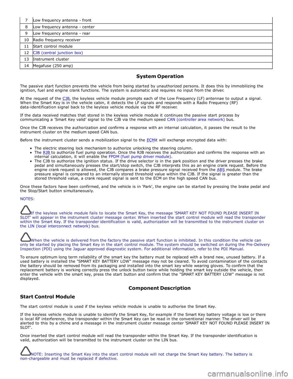
7 Low frequency antenna - front 8 Low frequency antenna - center 9 Low frequency antenna - rear 10 Radio frequency receiver 11 Start control module 12 CJB (central junction box) 13 Instrument cluster 14 Megafuse (250 amp)
System Operation
The passive start function prevents the vehicle from being started by unauthorized persons. It does this by immobilizing the
ignition, fuel and engine crank functions. The system is automatic and requires no input from the driver.
At the request of the CJB, the keyless vehicle module prompts each of the Low Frequency (LF) antennae to output a signal. When the Smart Key is in the vehicle cabin, it detects the LF signals and responds with a Radio Frequency (RF)
data-identification signal back to the keyless vehicle module via the RF receiver.
If the data received matches that stored in the keyless vehicle module it continues the passive start process by
communicating a 'Smart Key valid’ signal to the CJB via the medium speed CAN (controller area network) bus.
Once the CJB receives the authorization and confirms a response with an internal calculation, it passes the result to the
instrument cluster on the medium speed CAN bus.
Before the instrument cluster sends a mobilization signal to the ECMit will exchange encrypted data with: The electric steering lock mechanism to authorize unlocking the steering column.
The RJB to authorize fuel pump operation. Once the RJB receives the authorization and confirms the response with an internal calculation, it will enable the FPDM (fuel pump driver module).
The CJB to authorize the ignition status. If the drive selector is in the park position and the driver presses the brake
pedal and simultaneously presses the start/stop switch, the CJB interprets this as an engine crank request. Before the
engine crank request is allowed, the CJB compares a brake pressure signal received from the ABS module. The brake pressure signal is compared to an internally stored threshold value within the CJB. If the signal is greater than the
stored threshold value, a crank request signal is sent to the ECM on the high speed CAN bus.
Once these factors have been confirmed, and the vehicle is in 'Park', the engine can be started by pressing the brake pedal and
the Stop/Start button simultaneously.
NOTES:
If the keyless vehicle module fails to locate the Smart Key, the message 'SMART KEY NOT FOUND PLEASE INSERT IN
SLOT' will appear in the instrument cluster message center. When inserted the start control module will read the transponder
within the Smart Key. If the transponder identification is valid, authorization will be transmitted to the instrument cluster on
the LIN (local interconnect network) bus.
When the vehicle is delivered from the factory the passive start function is inhibited. In this condition the vehicle can
only be started by placing the Smart Key in the start control module. The system should be switched on during the Pre-Delivery
Inspection (PDI) using the Jaguar approved diagnostic system. For additional information, refer to the PDI Manual.
To ensure optimum long term reliability of the smart key the battery must be replaced with a brand new, unused battery. If a
used battery is installed the "SMART KEY BATTERY LOW" message may not be cleared. To avoid contamination of the contacts
the battery should be removed from its packaging and installed into the smart key while wearing gloves. To confirm that the
replacement battery is working correctly press the unlock button twice while holding the smart key outside the vehicle, then
enter the vehicle with the smart key, press the start button and confirm that the "SMART KEY BATTERY LOW" message is not
displayed.
Start Control Module Component Description
The start control module is used if the keyless vehicle module is unable to authorise the Smart Key.
If the keyless vehicle module is unable to identify the Smart Key, for example if the Smart Key battery voltage is low or there
is local RF interference, the transponder within the Smart Key can be read in the conventional manner. The driver will be
alerted to this by a chime and a message in the instrument cluster message center 'SMART KEY NOT FOUND PLEASE INSERT IN
SLOT'.
Once inserted the start control module will read the transponder within the Smart Key. If the transponder identification is
valid, authorization will be transmitted to the instrument cluster on the LIN bus.
NOTE: Inserting the Smart Key into the start control module will not charge the Smart Key battery. The battery is
non-chargeable and must be replaced if defective.