Page 1363 of 3039

Defaults to base mapping for the ignition timing, with no cylinder correction
Disables the VCT system.
ENGINE COOLANT TEMPERATURE SENSORS
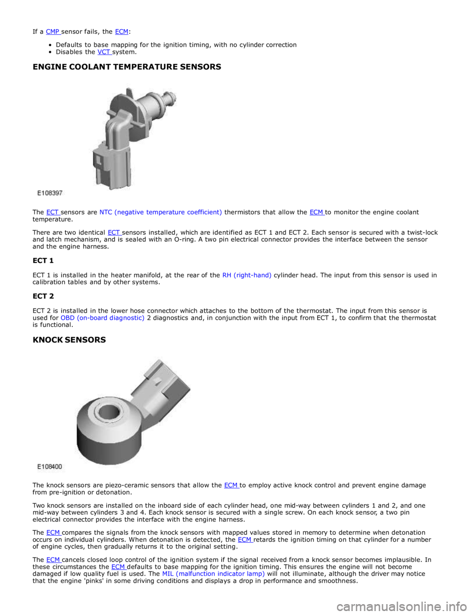
The ECT sensors are NTC (negative temperature coefficient) thermistors that allow the ECM to monitor the engine coolant temperature.
There are two identical ECT sensors installed, which are identified as ECT 1 and ECT 2. Each sensor is secured with a twist-lock and latch mechanism, and is sealed with an O-ring. A two pin electrical connector provides the interface between the sensor
and the engine harness.
ECT 1
ECT 1 is installed in the heater manifold, at the rear of the RH (right-hand) cylinder head. The input from this sensor is used in
calibration tables and by other systems.
ECT 2
ECT 2 is installed in the lower hose connector which attaches to the bottom of the thermostat. The input from this sensor is
used for OBD (on-board diagnostic) 2 diagnostics and, in conjunction with the input from ECT 1, to confirm that the thermostat
is functional.
KNOCK SENSORS
The knock sensors are piezo-ceramic sensors that allow the ECM to employ active knock control and prevent engine damage from pre-ignition or detonation.
Two knock sensors are installed on the inboard side of each cylinder head, one mid-way between cylinders 1 and 2, and one
mid-way between cylinders 3 and 4. Each knock sensor is secured with a single screw. On each knock sensor, a two pin
electrical connector provides the interface with the engine harness.
The ECM compares the signals from the knock sensors with mapped values stored in memory to determine when detonation occurs on individual cylinders. When detonation is detected, the ECM retards the ignition timing on that cylinder for a number of engine cycles, then gradually returns it to the original setting.
The ECM cancels closed loop control of the ignition system if the signal received from a knock sensor becomes implausible. In these circumstances the ECM defaults to base mapping for the ignition timing. This ensures the engine will not become damaged if low quality fuel is used. The MIL (malfunction indicator lamp) will not illuminate, although the driver may notice
that the engine 'pinks' in some driving conditions and displays a drop in performance and smoothness.
Page 1369 of 3039

Published: 16-Sep-2013
Electronic Engine Controls - V8 S/C 5.0L Petrol - Electronic Engine Controls
Diagnosis and Testing
Principle of Operation
For a detailed description of electronic engine controls, refer to the relevant Description and Operation section of the workshop
manual. REFER to: (303-14D Electronic Engine Controls - V8 S/C 5.0L Petrol)
Electronic Engine Controls (Description and Operation), Electronic Engine Controls (Description and Operation), Electronic Engine Controls (Description and Operation).
Inspection and Verification
1. Verify the customer concern.
2. Visually inspect for obvious signs of damage and system integrity.
Visual Inspection
Mechanical Electrical
Engine oil level and condition
Cooling system coolant level
Fuel level
Fuel contamination/grade/quality
Throttle body
Front End Accessory Drive (FEAD) belt
Air cleaner condition
Fuses
Wiring harness
Electrical connector(s)
Sensor(s)
Engine Control Module
Transmission Control Module
3. If an obvious cause for an observed or reported concern is found, correct the cause (if possible) before proceeding to
the next step.
4. If the cause is not visually evident, verify the customer concern and refer to the Symptom Chart below, alternatively,
check for Diagnostic Trouble Codes (DTCs) and refer to the DTC Index.
Symptom Chart
Symptom Possible Cause Action Engine non-start Engine does not crank
Security system /Immobilizer
engaged
Engine in shut-down mode
ECM relay
Battery
Starting system
Engine seized
Check that the security system is disarmed
Read DTCs and refer to DTC Index in this
section for ECM relay tests
Ensure the battery is in fully charged and
serviceable condition
For starting system tests refer to the
relevant section of the workshop manual
For engine system tests refer to the relevant
section of the workshop manual Engine cranks, but does not fire
Engine breather system
disconnected/restricted
Ignition system
Fuel system
Electronic engine controls
Ensure the engine breather system is free
from restriction and is correctly installed
For ignition system tests refer to the
relevant section of the workshop manual
For fuel system tests refer to the relevant
section of the workshop manual
Read DTCs and refer to DTC Index in this
section for electronic engine control tests Engine cranks and fires, but will not
start
Evaporative emissions purge
valve
Fuel pump
Spark plugs
Ignition coil failure(s)
For purge valve tests refer to the relevant
section of the workshop manual
For fuel system tests refer to the relevant
section of the workshop manual
For ignition system tests refer to the
relevant section of the workshop manual Difficult to start Difficult cold start
Check engine coolant
level/anti-freeze content
Battery
Electronic engine controls
Exhaust gas recirculation
Check the engine coolant level and
condition. Refer to the relevant sections of
the workshop manual
Ensure the battery is in a fully charged and
serviceable condition. Refer to the battery
Page 1387 of 3039
Published: 19-Aug-2013
Electronic Engine Controls - V8 S/C 5.0L Petrol - Engine Coolant Temperature
(ECT) Sensor
Removal and Installation
Removal
NOTES:
Some variation in the illustrations may occur, but the essential information is always correct.
Removal steps in this procedure may contain installation details.
1. WARNING: Do not work on or under a vehicle supported only by a jack.
Always support the vehicle on safety stands.
Raise and support the vehicle.
2. Refer to: Cooling System Partial Draining, Filling and Bleeding (303-03B Engine Cooling - V6 3.0L Petrol, General Procedures).
3. Refer to: Catalytic Converter RH (309-00C Exhaust System - V8 5.0L Petrol/V8 S/C 5.0L Petrol, Removal and Installation).
4. Torque: 48 Nm
Page 1388 of 3039
Installation 5. WARNING: Fluid loss is unavoidable, use absorbent
cloth or a container to collect the fluid.
CAUTION: Engine coolant will damage the paint
finished surfaces. If spilt, immediately remove the coolant
and clean the area with water.
Lift the tang and rotate the engine coolant temperature
(ECT) sensor counter clockwise.
1. To install, reverse the removal procedure.
Page 1480 of 3039
3. Torque: 5 Nm 4.
5.
Clamp the hoses to minimize coolant loss.
6. CAUTIONS:
Be prepared to collect escaping fluids.
Make sure that all openings are sealed. Use new
blanking caps. www.JagDocs.com
Page 1487 of 3039

30. CAUTION: Observe the engine temperature warning light. If the
warning light is displayed, switch off immediately and allow to cool.
Failure to follow this instruction may cause damage to the vehicle.
Raise the engine speed to 2000 RPM and maintain at 2000 RPM until the
engine cooling fan operates.
31. CAUTION: Switch off the engine and allow the coolant temperature
to go cold.
Switch the engine off and allow to cool.
32. Visually check the engine and cooling system for signs of coolant
leakage.
33. WARNINGS:
When releasing the cooling system pressure, cover the coolant
expansion tank cap with a thick cloth.
Since injury such as scalding could be caused by escaping steam or
coolant, make sure the vehicle cooling system is cool prior to carrying
out this procedure.
CAUTIONS:
Make sure the coolant level remains above the "COLD FILL RANGE"
lower level mark.
Anti-freeze concentration must be maintained at 50%.
NOTE: When the cooling system is warm, the coolant will be
approximately 10mm above the upper level mark on the expansion tank
with the cap removed.
Check and top-up the coolant if required.
34. Refer to: Transmission Fluid Level Check (307-01B Automatic Transmission/Transaxle - TDV6 3.0L Diesel /V8 5.0L Petrol/V8 S/C 5.0L
Petrol, General Procedures).
Page 1496 of 3039
Installation
1. Torque: 5 Nm
2.
3.
Clamp the hoses to minimize coolant loss.
4. CAUTIONS:
Be prepared to collect escaping fluids.
Make sure that all openings are sealed. Use new
blanking caps.
Page 1503 of 3039

28. CAUTION: Observe the engine temperature warning light. If the
warning light is displayed, switch off immediately and allow to cool.
Failure to follow this instruction may cause damage to the vehicle.
Raise the engine speed to 2000 RPM and maintain at 2000 RPM until the
engine cooling fan operates.
29. CAUTION: Switch off the engine and allow the coolant temperature
to go cold.
Switch the engine off and allow to cool.
30. Visually check the engine and cooling system for signs of coolant
leakage.
31. WARNINGS:
When releasing the cooling system pressure, cover the coolant
expansion tank cap with a thick cloth.
Since injury such as scalding could be caused by escaping steam or
coolant, make sure the vehicle cooling system is cool prior to carrying
out this procedure.
CAUTIONS:
Make sure the coolant level remains above the "COLD FILL RANGE"
lower level mark.
Anti-freeze concentration must be maintained at 50%.
NOTE: When the cooling system is warm, the coolant will be
approximately 10mm above the upper level mark on the expansion tank
with the cap removed.
Check and top-up the coolant if required.
32. Refer to: Transmission Fluid Level Check (307-01B Automatic Transmission/Transaxle - TDV6 3.0L Diesel /V8 5.0L Petrol/V8 S/C 5.0L
Petrol, General Procedures).