Page 1708 of 3039
Published: 11-May-2011
Climate Control - Control Components - System Operation and Component Description
Description and Operation
Control Diagram
NOTE: A = Hardwired; N = Medium speed CAN (controller area network) bus; O = LIN (local interconnect network) bus; P
= Media orientated system transport (MOST) ring.
Item Description 1 Battery 2 BJB (battery junction box) 3 CJB (central junction box) 4 Auxiliary coolant pump Comments:
All except 3.0L vehicles; 5.0L version shown, 3.0L diesel version similar.
Page 1726 of 3039
6. CAUTION: Be prepared to collect escaping coolant.
Torque: 9 Nm
7.
Installation
1. To install, reverse the removal procedure.
Page 1767 of 3039

7 ECT (engine coolant temperature) sensor 8 Ambient temperature sensor 9 Electric booster heater 10 Face/Feet distribution stepper motor 11 RH (right-hand) temperature blend stepper motor 12 LH (left-hand) temperature blend stepper motor 13 Windshield (defrost) distribution stepper motor 14 ATC (automatic temperature control) module 15 150 A megafuse
General System Operation
Operation of the electric booster heater is controlled by the ATC module, which communicates with the micro-controller in the booster heater using the LIN bus. The temperature requested by the ATC module is based on:
The ambient air temperature.
The engine coolant temperature.
The temperatures selected on the integrated control panel.
The blower must be running for the electric booster heater to operate.
If electrical load management is in force, electric booster heater performance is reduced. For additional information, refer to:
Electronic Engine Controls (303-14A, Description and Operation),
Electronic Engine Controls (303-14B Electronic Engine Controls - V6 3.0L Petrol, Description and Operation), Electronic Engine Controls (303-14C, Description and Operation).
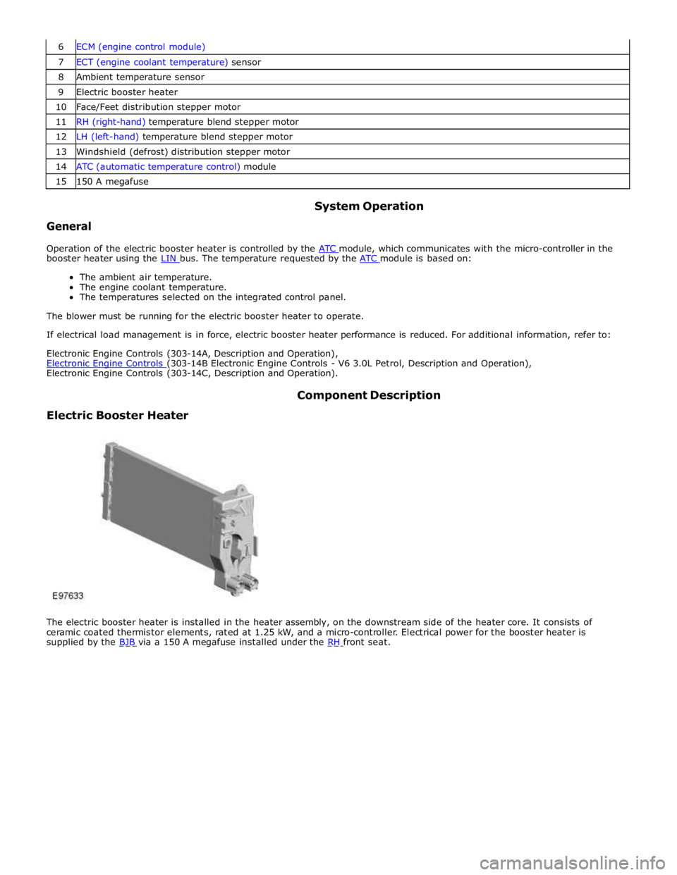
Electric Booster Heater Component Description
The electric booster heater is installed in the heater assembly, on the downstream side of the heater core. It consists of
ceramic coated thermistor elements, rated at 1.25 kW, and a micro-controller. Electrical power for the booster heater is
supplied by the BJB via a 150 A megafuse installed under the RH front seat.
Page 1768 of 3039
Auxiliary Climate Control - Auxiliary Coolant Flow Pump
Removal and Installation
Removal Published: 11-May-2011
1. WARNING: Do not work on or under a vehicle supported only by a jack.
Always support the vehicle on safety stands.
Raise and support the vehicle.
2. Refer to: Air Deflector (501-02, Removal and Installation).
3.
4.
lose.
5.
lose.
NOTE: Clamp the coolant hose to minimize coolant
NOTE: Clamp the coolant hose to minimize coolant
Page 1769 of 3039
6.
Installation
1.
2.
lose.
NOTE: Clamp the coolant hose to minimize coolant
Page 1770 of 3039
3.
lose.
4. NOTE: Clamp the coolant hose to minimize coolant
5. Lower the vehicle.
6. Remove the coolant expansion tank pressure cap.
7. Fill the cooling system up to the MAX mark on the coolant expansion
tank using a fifty percent mixture of Jaguar Premium Cooling System
Fluid or equivalent, meeting Jaguar specification WSS M97B44-D and
fifty percent water.
8. Install the coolant expansion tank pressure cap.
9. Start and run the engine.
10. Set the heating system to MAX heat, the blower motor to MAX speed
and the air distribution to the instrument panel registers.
11. CAUTION: Observe the engine temperature gauge. If the engine
starts to over-heat switch off immediately and allow to cool. Failure to
follow this instruction may cause damage to the vehicle
Allow the engine to run until hot air is emitted from the instrument
panel registers, while observing the engine temperature gauge.
12. Switch the engine off.
13. Allow the engine to cool.
Page 1771 of 3039

14. WARNINGS:
Never remove the coolant expansion tank cap under any
circumstances while the engine is operating. Failure to follow this
instruction may result in personal injury.
To avoid having scalding hot coolant or steam blowing out of the
cooling system, use extreme care when removing the coolant pressure
cap from a hot cooling system. Wait until the engine has cooled, then
wrap a thick cloth around the coolant pressure cap and turn it slowly
until the pressure begins to release. Step back while the pressure is
released from the system. When certain all the pressure has been
released (still with a cloth) turn and remove the coolant pressure cap
from the coolant expansion tank. Failure to follow these instructions may
result in personal injury.
Release the cooling system pressure.
15. Fill the cooling system up to the MAX mark on the coolant expansion
tank using a fifty percent mixture of Jaguar Premium Cooling System
Fluid or equivalent, meeting Jaguar specification WSS M97B44-D and
fifty percent water.
16. Install the coolant expansion tank pressure cap.
17. Raise the vehicle.
18. Check all coolant hoses for visible signs of coolant leaks.
19. Install the air deflector.
Refer to: Air Deflector (501-02, Removal and Installation).
www.JagDocs.com
Page 1784 of 3039
7 Instrument cluster 8 Steering column motor 9 High speed CAN bus connection to other vehicle systems 10 Engine oil pressure switch 11 Steering column adjustment switch 12 Brake fluid level switch 13 LH (left-hand) steering column multifunction switch 14 Start control module 15 Clockspring 16 RH (right-hand) steering column multifunction switch 17 Engine coolant level sensor 18 Auxiliary lighting switch
WARNING INDICATOR FUNCTIONALITY System Operation
Item Description 1 LH turn signal 2 RH turn signal 3 Brake warning 4 Brake warning (NAS) 5 Forward alert 6 Automatic Speed Limiter (ASL) 7 Adaptive speed control 8 ABS (anti-lock brake system) warning 9 ABS warning (NAS) 10 Malfunction Indicator Lamp (MIL) 11 Tire Pressure Monitoring System (TPMS) 12 Airbag warning 13 Front fog lamps 14 Dynamic Stability Control (DSC) warning 15 Seat belt warning 16 Side lamps 17 High beam 18 Rearfoglamps