2010 INFINITI QX56 brake
[x] Cancel search: brakePage 1811 of 4210
![INFINITI QX56 2010 Factory Service Manual EC-458
< ECU DIAGNOSIS >[VK56DE]
ECM
DTC Inspection Priority Chart
INFOID:0000000005149497
If some DTCs are displayed at the same time, perform inspections one by one based on the following priority
c INFINITI QX56 2010 Factory Service Manual EC-458
< ECU DIAGNOSIS >[VK56DE]
ECM
DTC Inspection Priority Chart
INFOID:0000000005149497
If some DTCs are displayed at the same time, perform inspections one by one based on the following priority
c](/manual-img/42/57032/w960_57032-1810.png)
EC-458
< ECU DIAGNOSIS >[VK56DE]
ECM
DTC Inspection Priority Chart
INFOID:0000000005149497
If some DTCs are displayed at the same time, perform inspections one by one based on the following priority
chart.
Priority Detected items (DTC)
1 • U0101 CAN communication line • U1001 CAN communication line
• P0101 P0102 P0103 Mass air flow sensor
• P0112 P0113 P0127 Intake air temperature sensor
• P0116 P0117 P0118 P0125 Engine coolant temperature sensor
• P0122 P0123 P0222 P0223 P1225 P1226 P2135 Throttle position sensor
• P0128 Thermostat function
• P0181 P0182 P0183 Fuel tank temperature sensor
• P0327 P0328 P0332 P0333 Knock sensor
• P0335 Crankshaft position sensor (POS)
• P0340 Camshaft position sensor (PHASE)
• P0460 P0461 P0462 P0463 Fuel level sensor
• P0500 Vehicle speed sensor
• P0605 P0607 ECM
• P0643 Sensor power supply
• P0700 TCM
• P0705 Park/neutral position (PNP) switch
• P0850 Park/neutral position (PNP) switch
• P1550 P1551 P1552 P1553 P1554 Battery current sensor
• P1610 - P1615 NATS
• P2122 P2123 P2127 P2128 P2138 Accelerator pedal position sensor
2 • P0031 P0032 P0051 P0052 Air fuel ratio (A/F) sensor 1 heater • P0037 P0038 P0057 P0058 Heated oxygen sensor 2 heater
• P0075 P0081 Intake valve timing control solenoid valve
• P0130 P0131 P0132 P0133 P0150 P0151 P0152 P0153 P2A00 P2A03 Air fuel ratio (A/F) sensor 1
• P0137 P0138 P0139 P0157 P0158 P0159 Heated oxygen sensor 2
• P0441 EVAP control system purge flow monitoring
• P0443 P0444 P0445 EVAP canister purge volume control solenoid valve
• P0447 P0448 EVAP canister vent control valve
• P0451 P0452 P0453 EVAP control system pressure sensor
• P0550 Power steering pressure sensor
• P0603 ECM power supply
• P0710 P0717 P0720 P0731 P0732 P0733 P0734 P0735 P0740 P0744 P0745 P1730 P1752 P1757 P1762 P1767 P1772 P1774 A/T related sensors, solenoid valves and switches
• P1217 Engine over temperature (OVERHEAT)
• P1140 P1145 Intake valve timing control position sensor
• P1805 Brake switch
• P2100 P2103 P2118 Electric throttle control actuator
• P2101 Electric throttle control function
3 • P0011 P0021 Intake valve timing control • P0171 P0172 P0174 P0175 Fuel injection system function
• P0300 - P0308 Misfire
• P0420 P0430 Three way catalyst function
• P0442 EVAP control system (SMALL LEAK)
• P0455 EVAP control system (GROSS LEAK)
• P0456 EVAP control sys tem (VERY SMALL LEAK)
• P0506 P0507 Idle speed control system
• P1148 P1168 Closed loop control
• P1211 TCS control unit
• P1212 TCS communication line
• P1421 Cold start control
• P1564 ICC/ASCD steering switch
• P1568 ICC command value
• P1572 ICC/ASCD brake switch
• P1574 ICC/ASCD vehicle speed sensor
• P2119 Electric throttle control actuator
Revision: April 20092010 QX56
Page 1815 of 4210
![INFINITI QX56 2010 Factory Service Manual EC-462
< ECU DIAGNOSIS >[VK56DE]
ECM
*1: 1st trip DTC No. is the same as DTC No.
*2: This number is prescribed by SAE J2012.BAT CURRENT SENSOR
P15541554—2—EC-324
ASCD SW P15641564—1—EC-328
( INFINITI QX56 2010 Factory Service Manual EC-462
< ECU DIAGNOSIS >[VK56DE]
ECM
*1: 1st trip DTC No. is the same as DTC No.
*2: This number is prescribed by SAE J2012.BAT CURRENT SENSOR
P15541554—2—EC-324
ASCD SW P15641564—1—EC-328
(](/manual-img/42/57032/w960_57032-1814.png)
EC-462
< ECU DIAGNOSIS >[VK56DE]
ECM
*1: 1st trip DTC No. is the same as DTC No.
*2: This number is prescribed by SAE J2012.BAT CURRENT SENSOR
P15541554—2—EC-324
ASCD SW P15641564—1—EC-328
(Models
with ICC) EC-332
(Models
with ASCD)
ICC COMMAND VALUE*
9P1568 1568—1—EC-336
ASCD BRAKE SW P15721572—1—EC-337
(Models
with ICC) EC-344
(Models
with ASCD)
ASCD VHL SPD SEN*
8P1574 1574—1—EC-349
(Models
with ICC)
EC-351
(Models
with ASCD)
ID DISCARD IMM-ECM P16111611—2—SEC-41
CHAIN OF ECM-IMMU P16121612—2—SEC-37
CHAIN OF IMMU-KEY P16141614—2—SEC-31
DIFFERENCE OF KEY P16151615—2—SEC-34
INTERLOCK P17301730—1×TM-78
INPUT CLUTCH SOLENOID P17521752—1×TM-82
FR BRAKE SOLENOID P17571757—1×TM-84
DRCT CLUTCH SOLENOID P17621762—1×TM-86
HLR CLUTCH SOLENOID P17671767—1×TM-88
L C BRAKE SOLENOID P17721772—1×TM-90
L C BRAKE SOLENOID P17741774—1×TM-92
BRAKE SW/CIRCUIT P18051805—2—EC-353
ETC MOT PWR-B1 P21002100—1×EC-356
ETC FUNCTION/CIRC-B1 P21012101—1×EC-359
ETC MOT PWR P21032103—1×EC-356
ETC MOT-B1 P21182118—1×EC-363
ETC ACTR-B1 P21192119—1×EC-365
APP SEN 1/CIRC P21222122—1×EC-367
APP SEN 1/CIRC P21232123—1×EC-367
APP SEN 2/CIRC P21272127—1×EC-370
APP SEN 2/CIRC P21282128—1×EC-370
TP SENSOR-B1 P21352135—1×EC-374
APP SENSOR P21382138—1×EC-378
A/F SENSOR1 (B1) P2A002A00—2×EC-382
A/F SENSOR1 (B2) P2A032A03—2×EC-382
Items
(CONSULT-IIl screen terms) DTC*
1
SRT code Trip
MILReference
page
CONSULT-IIl
GST*
2ECM*3
Revision: April 20092010 QX56
Page 1903 of 4210

EM-52
< ON-VEHICLE REPAIR >
TIMING CHAIN
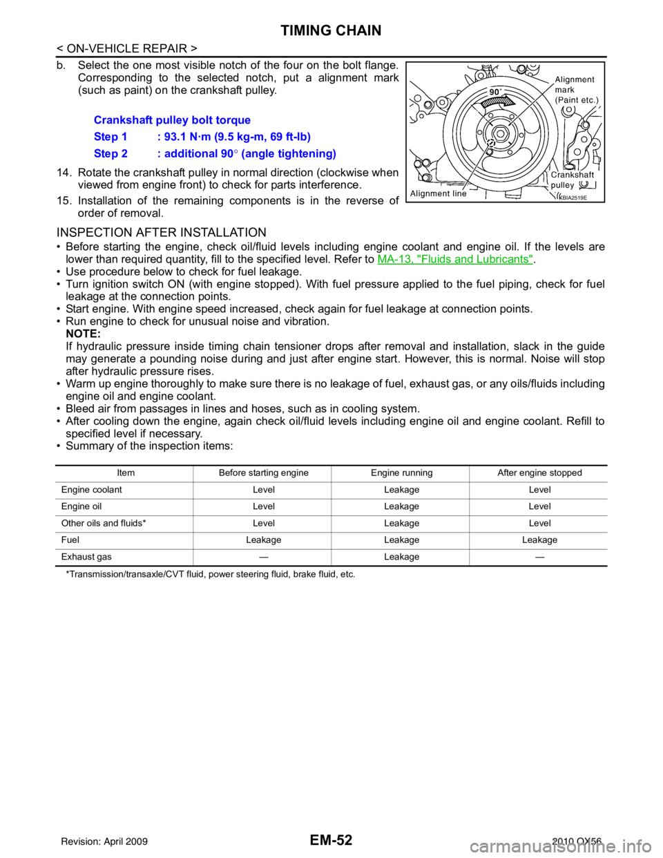
b. Select the one most visible notch of the four on the bolt flange.Corresponding to the selected notch, put a alignment mark
(such as paint) on the crankshaft pulley.
14. Rotate the crankshaft pulley in normal direction (clockwise when viewed from engine front) to check for parts interference.
15. Installation of the remaining components is in the reverse of order of removal.
INSPECTION AFTER INSTALLATION
• Before starting the engine, check oil/fluid levels in cluding engine coolant and engine oil. If the levels are
lower than required quantity, fill to the specified level. Refer to MA-13, "
Fluids and Lubricants".
• Use procedure below to check for fuel leakage.
• Turn ignition switch ON (with engine stopped). With fuel pressure applied to the fuel piping, check for fuel leakage at the connection points.
• Start engine. With engine speed increased, che ck again for fuel leakage at connection points.
• Run engine to check for unusual noise and vibration. NOTE:
If hydraulic pressure inside timing chain tensioner drops after removal and installation, slack in the guide
may generate a pounding noise during and just after engine start. However, this is normal. Noise will stop
after hydraulic pressure rises.
• Warm up engine thoroughly to make sure there is no leakage of fuel, exhaust gas, or any oils/fluids including engine oil and engine coolant.
• Bleed air from passages in lines and hoses, such as in cooling system.
• After cooling down the engine, again check oil/fluid levels including engine oil and engine coolant. Refill to
specified level if necessary.
• Summary of the inspection items:
*Transmission/transaxle/CVT fluid, power steering fluid, brake fluid, etc.
Crankshaft pulley bolt torque
Step 1 : 93.1 N·m (9.5 kg-m, 69 ft-lb)
Step 2 : additional 90 ° (angle tightening)
KBIA2519E
Item Before starting engine Engine runningAfter engine stopped
Engine coolant LevelLeakage Level
Engine oil LevelLeakage Level
Other oils and fluids* LevelLeakage Level
Fuel LeakageLeakageLeakage
Exhaust gas —Leakage —
Revision: April 20092010 QX56
Page 1921 of 4210

EM-70
< ON-VEHICLE REPAIR >
CYLINDER HEAD
• After cooling down the engine, again check oil/fluid levels including engine oil and engine coolant. Refill tospecified level if necessary.
• Summary of the inspection items:
*Transmission/transaxle/CVT fluid, power steering fluid, brake fluid, etc.
Exploded ViewINFOID:0000000005149009
Disassembly and AssemblyINFOID:0000000005149010
DISASSEMBLY
1. Remove the spark plug. Refer to EM-16, "Removal and Installation".
2. Remove the valve lifter. • Identify the installation positions, and store them without mixing them up.
Item Before starting engine Engine runningAfter engine stopped
Engine coolant LevelLeakage Level
Engine oil LevelLeakage Level
Other oils and fluids* LevelLeakage Level
Fuel LeakageLeakageLeakage
Exhaust gas —Leakage —
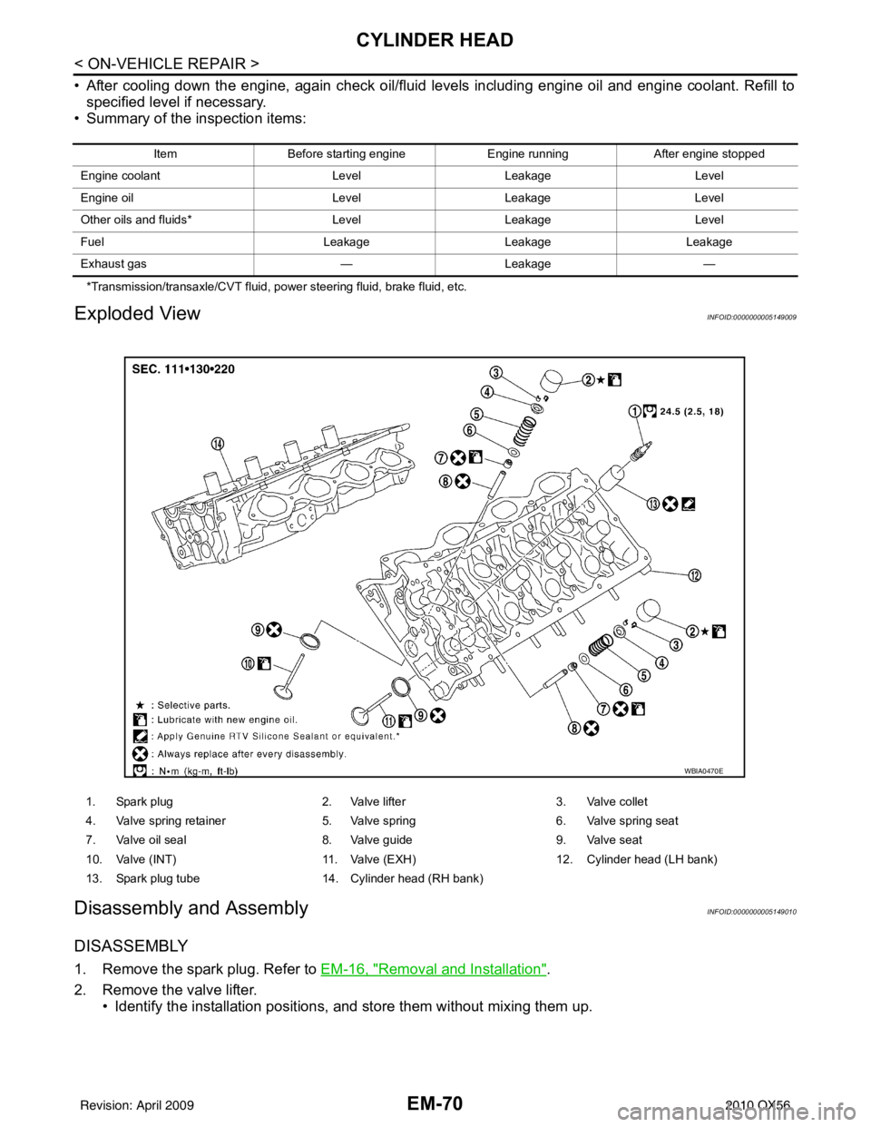
1. Spark plug 2. Valve lifter3. Valve collet
4. Valve spring retainer 5. Valve spring6. Valve spring seat
7. Valve oil seal 8. Valve guide9. Valve seat
10. Valve (INT) 11. Valve (EXH)12. Cylinder head (LH bank)
13. Spark plug tube 14. Cylinder head (RH bank)
WBIA0470E
Revision: April 20092010 QX56
Page 1930 of 4210

ENGINE ASSEMBLYEM-79
< REMOVAL AND INSTALLATION >
C
DE
F
G H
I
J
K L
M A
EM
NP
O
1. Release the fuel pressure. Refer to
EC-489, "Fuel Pressure Check".
2. Drain the engine coolant. Refer to CO-11, "
Changing Engine Coolant".
3. Drain the engine oil. Refer to LU-9, "
Changing Engine Oil".
4. Partially drain the A/T fluid. Refer to TM-150, "
Changing the A/T Fluid (ATF)".
5. Disconnect the battery negative and positive terminal. Refer to PG-74, "
Removal and Installation".
6. Remove the engine hood. Refer to DLK-234, "
Removal and Installation of Hood Assembly".
7. Remove the cowl extension. Refer to EXT-18, "
Removal and Installation".
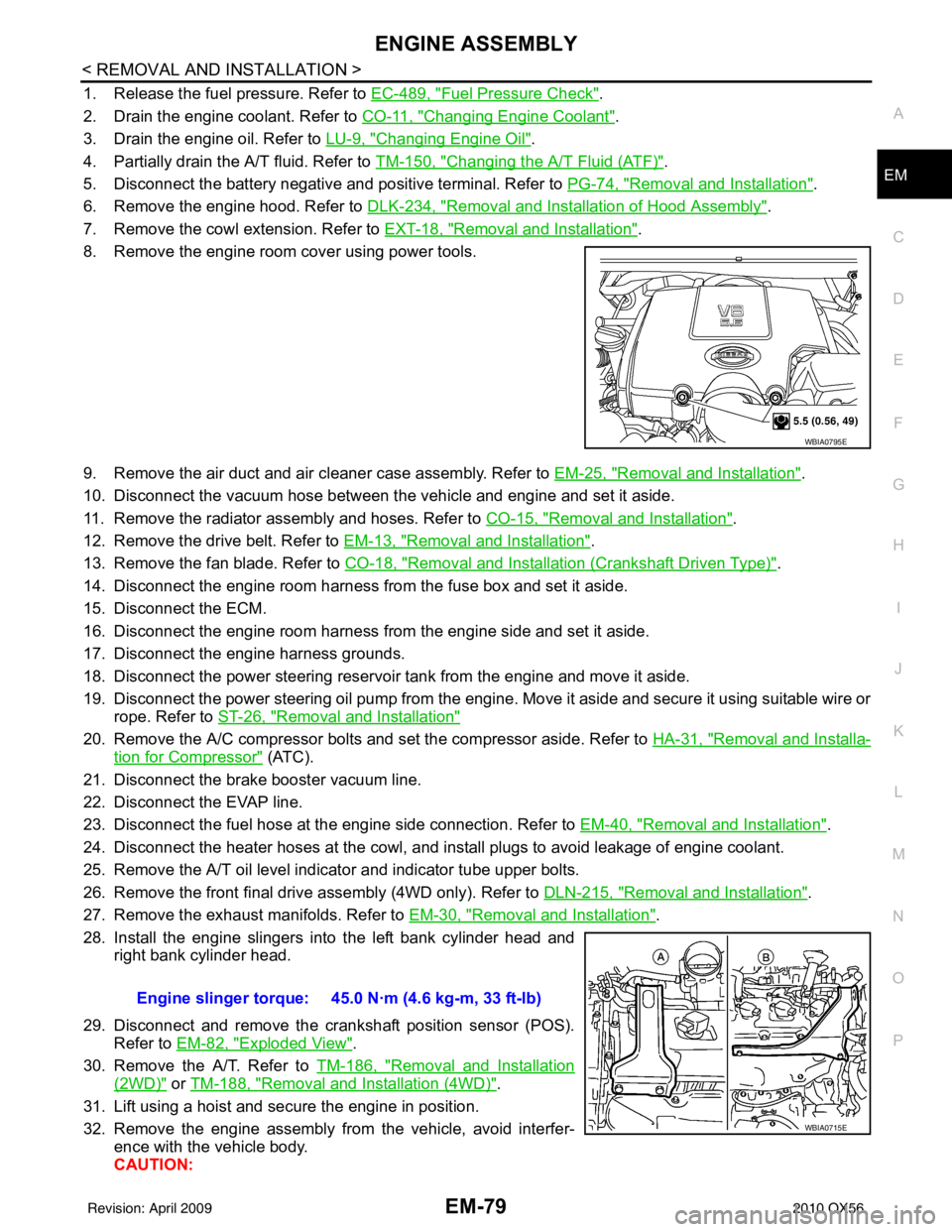
8. Remove the engine room cover using power tools.
9. Remove the air duct and air cleaner case assembly. Refer to EM-25, "
Removal and Installation".
10. Disconnect the vacuum hose between the vehicle and engine and set it aside.
11. Remove the radiator assembly and hoses. Refer to CO-15, "
Removal and Installation".
12. Remove the drive belt. Refer to EM-13, "
Removal and Installation".
13. Remove the fan blade. Refer to CO-18, "
Removal and Installation (Crankshaft Driven Type)".
14. Disconnect the engine room harness from the fuse box and set it aside.
15. Disconnect the ECM.
16. Disconnect the engine room harness from the engine side and set it aside.
17. Disconnect the engine harness grounds.
18. Disconnect the power steering reservoir t ank from the engine and move it aside.
19. Disconnect the power steering oil pump from the engine. Move it aside and secure it using suitable wire or rope. Refer to ST-26, "
Removal and Installation"
20. Remove the A/C compressor bolts and set the compressor aside. Refer to HA-31, "Removal and Installa-
tion for Compressor" (ATC).
21. Disconnect the brake booster vacuum line.
22. Disconnect the EVAP line.
23. Disconnect the fuel hose at the engine side connection. Refer to EM-40, "
Removal and Installation".
24. Disconnect the heater hoses at the cowl, and in stall plugs to avoid leakage of engine coolant.
25. Remove the A/T oil level indicator and indicator tube upper bolts.
26. Remove the front final drive assembly (4WD only). Refer to DLN-215, "
Removal and Installation".
27. Remove the exhaust manifolds. Refer to EM-30, "
Removal and Installation".
28. Install the engine slingers into the left bank cylinder head and right bank cylinder head.
29. Disconnect and remove the crankshaft position sensor (POS). Refer to EM-82, "
Exploded View".
30. Remove the A/T. Refer to TM-186, "
Removal and Installation
(2WD)" or TM-188, "Removal and Installation (4WD)".
31. Lift using a hoist and secure the engine in position.
32. Remove the engine assembly from the vehicle, avoid interfer- ence with the vehicle body.
CAUTION:
WBIA0795E
Engine slinger torque: 45.0 N·m (4.6 kg-m, 33 ft-lb)
WBIA0715E
Revision: April 20092010 QX56
Page 1932 of 4210

ENGINE ASSEMBLYEM-81
< REMOVAL AND INSTALLATION >
C
DE
F
G H
I
J
K L
M A
EM
NP
O
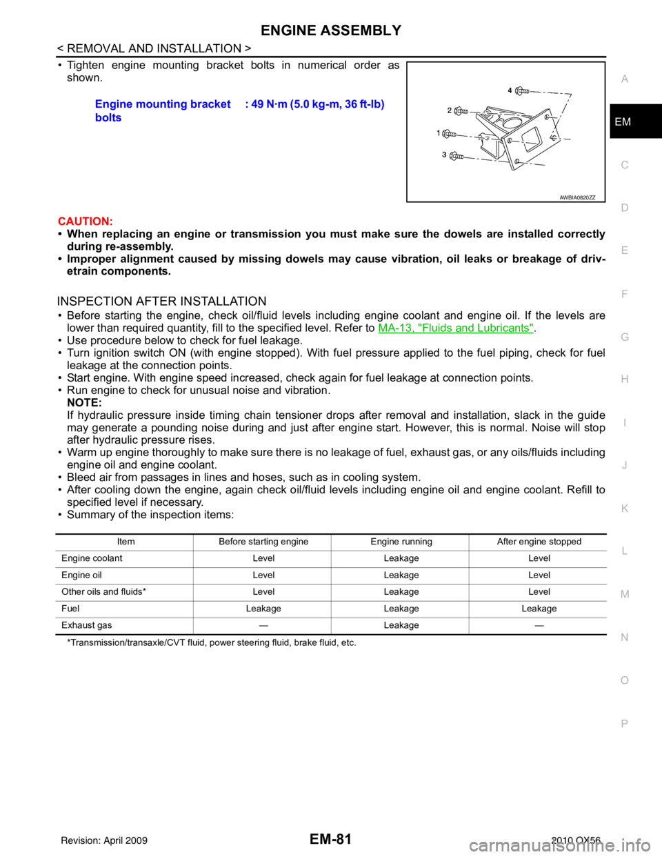
• Tighten engine mounting bracket bolts in numerical order as
shown.
CAUTION:
• When replacing an engine or tr ansmission you must make sure the dowels are installed correctly
during re-assembly.
• Improper alignment caused by missing dowels m ay cause vibration, oil leaks or breakage of driv-
etrain components.
INSPECTION AFTER INSTALLATION
• Before starting the engine, check oil/fluid levels including engine coolant and engine oil. If the levels are
lower than required quantity, fill to the specified level. Refer to MA-13, "
Fluids and Lubricants".
• Use procedure below to check for fuel leakage.
• Turn ignition switch ON (with engine stopped). With fuel pressure applied to the fuel piping, check for fuel leakage at the connection points.
• Start engine. With engine speed increased, check again for fuel leakage at connection points.
• Run engine to check for unusual noise and vibration. NOTE:
If hydraulic pressure inside timing chain tensioner drops after removal and installation, slack in the guide
may generate a pounding noise during and just after engine start. However, this is normal. Noise will stop
after hydraulic pressure rises.
• Warm up engine thoroughly to make sure there is no leakage of fuel, exhaust gas, or any oils/fluids including engine oil and engine coolant.
• Bleed air from passages in lines and hoses, such as in cooling system.
• After cooling down the engine, again check oil/fluid levels including engine oil and engine coolant. Refill to
specified level if necessary.
• Summary of the inspection items:
*Transmission/transaxle/CVT fluid, power steering fluid, brake fluid, etc.
Engine mounting bracket
bolts : 49 N·m (5.0 kg-m, 36 ft-lb)
AWBIA0820ZZ
Item
Before starting engine Engine runningAfter engine stopped
Engine coolant LevelLeakage Level
Engine oil LevelLeakage Level
Other oils and fluids* LevelLeakage Level
Fuel LeakageLeakage Leakage
Exhaust gas —Leakage —
Revision: April 20092010 QX56
Page 1985 of 4210

DAYTIME LIGHT SYSTEMEXL-9
< FUNCTION DIAGNOSIS >
C
DE
F
G H
I
J
K
M A
B
EXL
N
O P
DAYTIME LIGHT SYSTEM
System DiagramINFOID:0000000005369869
System DescriptionINFOID:0000000005146609
The headlamp system for Canada vehicles is equipped with a daytime light relay that activates the high beam
headlamps at approximately half illumination whenever the engine is operating. If the parking brake is applied
before the engine is started the daytime lights will not be illuminated. The daytime lights will illuminate once the
parking brake is released. Thereafter, the daytime lights will continue to operate when the parking brake is
applied.
Component Parts LocationINFOID:0000000005146610
AWLIA1751GB
AWLIA1626ZZ
Revision: April 20092010 QX56
Page 1986 of 4210

EXL-10
< FUNCTION DIAGNOSIS >
DAYTIME LIGHT SYSTEM
Component Description
INFOID:0000000005369870
After starting the engine with the parking brake releas ed and the combination switch (lighting and turn signal
switch) in the OFF or 1ST position, the headlamp high beam automatically turns on at a reduced intensity.
With the combination switch (lighting and turn signal switch) in the 2nd position or with autolamps ON, the
headlamps function the same as conventional light systems.
OPERATION
The BCM monitors inputs from the parking brake swit ch and the combination switch (lighting and turn signal
switch) to determine when to activate the daytime light system. The BCM sends a daytime light request to the
IPDM E/R via the CAN communication lines. The IPDM E/ R grounds the daytime light relay which in turn, pro-
vides power to the ground side of the LH high beam lamp. Power flows backward through the LH high beam
lamp to the IPDM E/R, through the high beam fuses, through the RH high beam lamp circuit to the RH high
beam lamp and on to ground. The high beam lamps are wired in series which causes them to illuminate at a
reduced intensity.
1. IPDM E/R E119, E122, E123, E124 2. BCM M18, M20 (view with instrument
panel removed)3. Daytime light relay E103
4. Combination switch (lighting and turn signal switch) M28 5. Combination meter M23, M24 6. Parking brake switch M11
Revision: April 20092010 QX56