2010 INFINITI QX56 brake
[x] Cancel search: brakePage 2717 of 4210
RECOMMENDED FLUIDS AND LUBRICANTSMA-13
< ON-VEHICLE MAINTENANCE >
C
DE
F
G H
I
J
K L
M B
MA
N
O A
RECOMMENDED FLUIDS AND LUBRICANTS
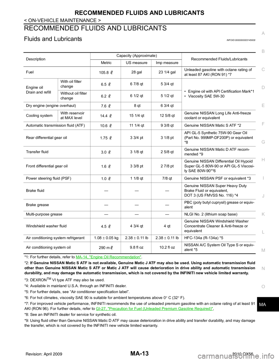
Fluids and LubricantsINFOID:0000000005145938
*1: For further details, refer to
MA-14, "Engine Oil Recommendation".
*2: If Genuine NISSAN Matic S ATF is not ava ilable, Genuine Matic J ATF may also be used. Using automatic transmission fluid
other than Genuine NISSAN Matic S ATF or Matic J ATF will cause deterioration in drive ability and automatic transmission
durability, and may damage the automatic transmission, which is not covered by the INFINITI new vehicle limited warranty.
*3: DEXRON
TM VI type ATF may also be used.
*4: Available in mainland U.S.A. through an INFINITI dealer.
*5: For further details, see “Air conditioner specification label”.
*6: For hot climates, viscosity SAE 90 is suitable for ambient temperatures above 0° C (32° F).
*7: For improved vehicle performance, INFINITI recommends the use of unleaded premium gasoline with an octane rating of at leas t 91
AKI (RON 96). For furt her details, refer to GI-27, "
Precaution for Fuel (Unleaded Premium Gasoline Required)",
*8: See an INFINITI dealer for service for synthetic oil.
*9: Using fluid other than Genuin e NISSAN Matic D ATF may cause deterioration in drive ability and transfer durability, and may damage
the transfer, which is not covered by the INFINITI new vehicle limited warranty. Description
Capacity (Approximate)
Recommended Fluids/Lubricants
Metric US measure Imp measure
Fuel 105.8 28 gal 23 1/4 gal Unleaded gasoline with octane rating of
at least 87 AKI (RON 91) *7
Engine oil
Drain and refill With oil filter
change
6.5
6 7/8 qt 5 3/4 qt
• Engine oil with API Certification Mark*1
• Viscosity SAE 5W-30
Without oil filter
change
6.2
6 1/2 qt 5 1/2 qt
Dry engine (engine overhaul) 7.6 8 qt
6 3/4 qt
Cooling system With reservoir
at MAX level
14.4
15 1/4 qt 12 5/8 qt Genuine NISSAN Long
Life Anti-freeze
coolant or equivalent
Automatic transmission fluid (ATF) 10.6 11 1/4 qt 9 3/8 qt Genuine NISSAN Matic S ATF *2
Rear differential gear oil 1.75 3 3/4 pt 3 1/8 pt API GL-5 Synthetic 75W-90 Gear Oil
(Part No. 999MP-DF200P) or equivalent
*8
Transfer fluid 3.0 3 1/8 qt 2 5/8 qt Genuine NISSAN Matic D ATF recom-
mended *9
Front differential gear oil 1.6 3 3/8 pt 2 7/8 pt Genuine NISSAN Differ
ential Oil Hypoid
Super GL-5 80W-90 or API GL-5 Viscosi-
ty SAE 80W-90**6
Power steering fluid (PSF) 1.0 1 1/8 qt 7/8 qt Genuine NISSAN PSF or equivalent *3
Brake fluid ———Genuine NISSAN S
uper Heavy Duty
Brake Fluid or equivalent,
DOT 3 (US FMVSS No. 116) *4
Brake grease ———PBC (poly butyl cuprysil) grease or equiv-
alent
Multi-purpose grease ——— NLGI No. 2 (lithium soap base)
Windshield washer fluid 4.5 4 3/4 qt
4 qtGenuine NISSAN Wind
shield Washer
Concentrate Cleaner & Anti-freeze or
equivalent
Air conditioning system refrigerant 1.08 ± 0.05 kg 2.38 ± 0.11 lb 2.38 ± 0.11 lb HFC-134a (R-134a) *5
Air conditioning system oil 290 m9.8 fl oz 10.2 fl oz NISSAN A/C System Oil Type S or equiv-
alent *5
Revision: April 20092010 QX56
Page 2731 of 4210
CHASSIS AND BODY MAINTENANCEMA-27
< ON-VEHICLE MAINTENANCE >
C
DE
F
G H
I
J
K L
M B
MA
N
O A
• If anything is found, repair or replace damaged parts.
A/T FLUID
A/T FLUID : Checking
the A/T Fluid (ATF)INFOID:0000000005403151
CAUTION:
If using the vehicle for towing, the A/T fluid must be replaced as specified. Refer to MA-9, "
Introduc-
tion of Periodic Maintenance".
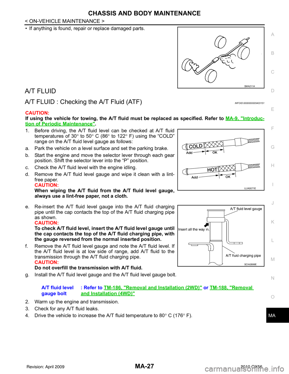
1. Before driving, the A/T fluid level can be checked at A/T fluid temperatures of 30 ° to 50 ° C (86 ° to 122° F) using the “COLD”
range on the A/T fluid level gauge as follows:
a. Park the vehicle on a level surface and set the parking brake.
b. Start the engine and move the selector lever through each gear position. Shift the selector lever into the “P” position.
c. Check the A/T fluid level with the engine idling.
d. Remove the A/T fluid level gauge and wipe it clean with a lint- free paper.
CAUTION:
When wiping the A/T fluid from the A/T fluid level gauge,
always use a lint-free paper, not a cloth.
e. Re-insert the A/T fluid level gauge into the A/T fluid charging pipe until the cap contacts the top of the A/T fluid charging pipe
as shown.
CAUTION:
To check A/T fluid level, insert th e A/T fluid level gauge until
the cap contacts the top of the A/T fluid charging pipe, with
the gauge reversed from the normal inserted position.
f. Remove the A/T fluid level gauge and note the A/T fluid level. If the A/T fluid level is at low side of range, add A/T fluid to the
transmission through the A/T fluid charging pipe.
CAUTION:
Do not overfill the tran smission with A/T fluid.
g. Install the A/T fluid level gauge and the A/T fluid level gauge bolt.
2. Warm up the engine and transmission.
3. Check for any A/T fluid leaks.
4. Drive the vehicle to increase the A/T fluid temperature to 80 ° C (176 ° F).
SMA211A
LLIA0071E
A/T fluid level
gauge bolt : Refer to
TM-186, "Removal and Installation (2WD)" or TM-188, "Removal
and Installation (4WD)"
SCIA2899E
Revision: April 20092010 QX56
Page 2738 of 4210
MA-34
< ON-VEHICLE MAINTENANCE >
CHASSIS AND BODY MAINTENANCE
Wheel balance (Maximum allowable imbalance):
WHEELS : RotationINFOID:0000000005403160
NOTE:
Follow the maintenance schedule for tire rotation service intervals. Refer to MA-9, "
Schedule 1" .
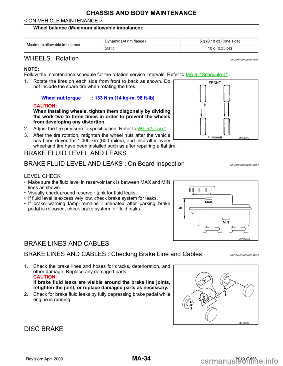
1. Rotate the tires on each side from front to back as shown. Do not include the spare tire when rotating the tires.
CAUTION:
When installing wheel s, tighten them diagonally by dividing
the work two to three times in order to prevent the wheels
from developing any distortion.
2. Adjust the tire pressure to specification. Refer to WT-52, "
Tire" .
3. After the tire rotation, retighten the wheel nuts after the vehicle has been driven for 1,000 km (600 miles), and also after every
wheel and tire have been installed such as after repairing a flat tire.
BRAKE FLUID LEVEL AND LEAKS
BRAKE FLUID LEVEL AND LEAK S : On Board InspectionINFOID:0000000005403161
LEVEL CHECK
• Make sure the fluid level in reservoir tank is between MAX and MIN
lines as shown.
• Visually check around reservoir tank for fluid leaks.
• If fluid level is excessively low, check brake system for leaks.
• If brake warning lamp remains illuminated after parking brake pedal is released, check brake system for fluid leaks.
BRAKE LINES AND CABLES
BRAKE LINES AND CABLES : Ch ecking Brake Line and CablesINFOID:0000000005259676
1. Check the brake lines and hoses for cracks, deterioration, and
other damage. Replace any damaged parts.
CAUTION:
If brake fluid leaks are visible around the brake line joints,
retighten the joint, or replace damaged parts as necessary.
2. Check for brake fluid leaks by fully depressing brake pedal while engine is running.
DISC BRAKE
Maximum allowable imbalance Dynamic (At rim flange) 5 g (0.18 oz) (one side)
Static
10 g (0.35 oz)
Wheel nut torque : 133 N·m (14 kg-m, 98 ft-lb)
SMA829C
LFIA0225E
SBR389C
Revision: April 20092010 QX56
Page 2739 of 4210
CHASSIS AND BODY MAINTENANCEMA-35
< ON-VEHICLE MAINTENANCE >
C
DE
F
G H
I
J
K L
M B
MA
N
O A
DISC BRAKE : Front Pad InspectionINFOID:0000000005403162
PA D W E A R
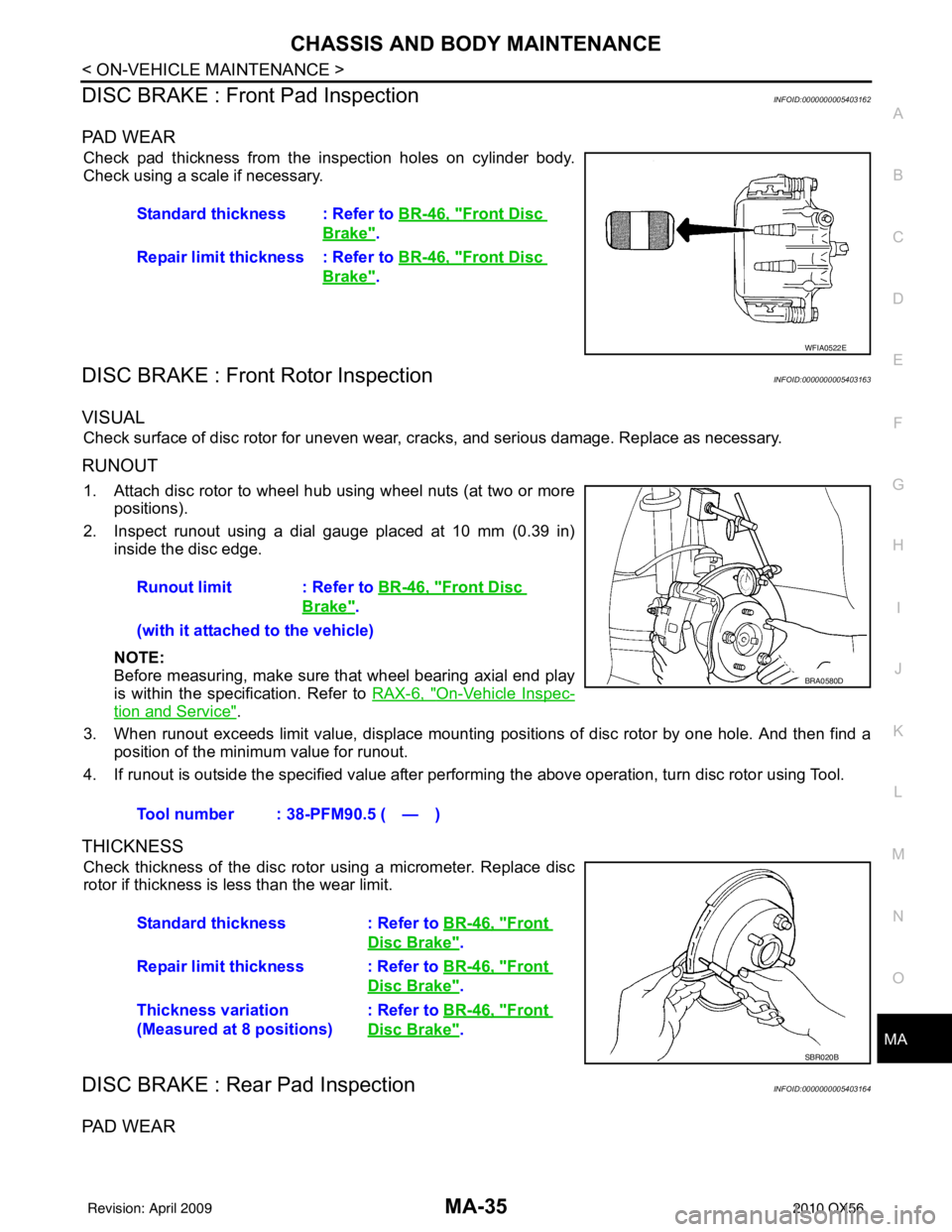
Check pad thickness from the inspection holes on cylinder body.
Check using a scale if necessary.
DISC BRAKE : Front Rotor InspectionINFOID:0000000005403163
VISUAL
Check surface of disc rotor for uneven wear, cracks, and serious damage. Replace as necessary.
RUNOUT
1. Attach disc rotor to wheel hub using wheel nuts (at two or more
positions).
2. Inspect runout using a dial gauge placed at 10 mm (0.39 in) inside the disc edge.
NOTE:
Before measuring, make sure that wheel bearing axial end play
is within the specification. Refer to RAX-6, "
On-Vehicle Inspec-
tion and Service".
3. When runout exceeds limit value, displace mounting positions of disc rotor by one hole. And then find a position of the minimum value for runout.
4. If runout is outside the specified value after performing the above operation, turn disc rotor using Tool.
THICKNESS
Check thickness of the disc rotor using a micrometer. Replace disc
rotor if thickness is less than the wear limit.
DISC BRAKE : Rear Pad InspectionINFOID:0000000005403164
PA D W E A R
Standard thickness : Refer to BR-46, "Front Disc
Brake".
Repair limit thickness : Refer to BR-46, "
Front Disc
Brake".
WFIA0522E
Runout limit : Refer to BR-46, "Front Disc
Brake".
(with it attached to the vehicle)
Tool number : 38-PFM90.5 ( — )
BRA0580D
Standard thickness : Refer to BR-46, "Front
Disc Brake".
Repair limit thickness : Refer to BR-46, "
Front
Disc Brake".
Thickness variation
(Measured at 8 positions) : Refer to
BR-46, "
Front
Disc Brake".
SBR020B
Revision: April 20092010 QX56
Page 2740 of 4210
MA-36
< ON-VEHICLE MAINTENANCE >
CHASSIS AND BODY MAINTENANCE
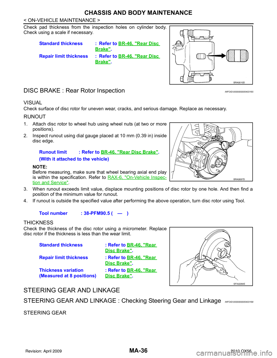
Check pad thickness from the inspection holes on cylinder body.
Check using a scale if necessary.
DISC BRAKE : Rear Rotor InspectionINFOID:0000000005403165
VISUAL
Check surface of disc rotor for uneven wear, cracks, and serious damage. Replace as necessary.
RUNOUT
1. Attach disc rotor to wheel hub using wheel nuts (at two or more
positions).
2. Inspect runout using dial gauge placed at 10 mm (0.39 in) inside disc edge.
NOTE:
Before measuring, make sure that wheel bearing axial end play
is within the specification. Refer to RAX-6, "
On-Vehicle Inspec-
tion and Service".
3. When runout exceeds limit value, displace mounting positions of disc rotor by one hole. And then find a position of the minimum value for runout.
4. If runout is outside the specified value after performing the above operation, turn disc rotor using Tool.
THICKNESS
Check the thickness of the disc rotor using a micrometer. Replace
disc rotor if the thickness is less than the wear limit.
STEERING GEAR AND LINKAGE
STEERING GEAR AND LINKAGE : Che cking Steering Gear and LinkageINFOID:0000000005403168
STEERING GEAR
Standard thickness : Refer to BR-46, "Rear Disc
Brake".
Repair limit thickness : Refer to BR-46, "
Rear Disc
Brake".
BRA0010D
Runout limit : Refer to BR-46, "Rear Disc Brake".
(With it attached to the vehicle)
Tool number : 38-PFM90.5 ( — )
BRA0697D
Standard thickness : Refer to BR-46, "Rear
Disc Brake".
Repair limit thickness : Refer to BR-46, "
Rear
Disc Brake".
Thickness variation
(Measured at 8 positions) : Refer to BR-46, "
Rear
Disc Brake".
SFIA2284E
Revision: April 20092010 QX56
Page 2764 of 4210

MWI-2
INFORMATION DISPLAY .........................................19
INFORMATION DISPLAY : System Diagram .........20
INFORMATION DISPLAY : System Description ....20
INFORMATION DISPLAY : Component Parts Lo-
cation ................................................................... ...
21
INFORMATION DISPLAY : Component Descrip-
tion ....................................................................... ...
21
DIAGNOSIS SYSTEM (METER) .......................22
Diagnosis Description .......................................... ...22
CONSULT-III Function (METER/M&A) ................ ...23
COMPONENT DIAGNOSIS ........................26
DTC U1000 CAN COMMUNICATION ............ ...26
DTC Logic ............................................................ ...26
Diagnosis Procedure .............................................26
DTC B2205 VEHICLE SPEED CIRCUIT ...........27
Description ........................................................... ...27
DTC Logic ...............................................................27
Diagnosis Procedure .............................................27
POWER SUPPLY AND GROUND CIRCUIT .....28
COMBINATION METER ........................................ ...28
COMBINATION METER : Diagnosis Procedure ....28
BCM (BODY CONTROL MODULE) ...................... ...29
BCM (BODY CONTROL MODULE) : Diagnosis
Procedure ...............................................................
29
IPDM E/R (INTELLIGENT POWER DISTRIBU-
TION MODULE ENGINE ROOM) .......................... ...
30
IPDM E/R (INTELLIGENT POWER DISTRIBU-
TION MODULE ENGINE ROOM) : Diagnosis Pro-
cedure .....................................................................
30
FUEL LEVEL SENSOR SIGNAL CIRCUIT .......32
Description ........................................................... ...32
Component Function Check ...................................32
Diagnosis Procedure .............................................32
Component Inspection ............................................33
OIL PRESSURE SWITCH SIGNAL CIRCUIT ...34
Description ..............................................................34
Component Function Check ...................................34
Diagnosis Procedure ..............................................34
Component Inspection ............................................34
PARKING BRAKE SWITCH SIGNAL CIR-
CUIT ...................................................................
35
Description ........................................................... ...35
Component Function Check ...................................35
Diagnosis Procedure ..............................................35
Component Inspection ............................................35
WASHER LEVEL SWITCH SIGNAL CIRCUIT ...36
Description ........................................................... ...36
Diagnosis Procedure ..............................................36
Component Inspection ............................................36
CLOCK ..............................................................37
Wiring Diagram .................................................... ...37
ECU DIAGNOSIS .......................................39
COMBINATION METER ................................. ...39
Reference Value .................................................. ...39
Wiring Diagram .......................................................41
Fail Safe ..................................................................58
DTC Index ...............................................................59
BCM (BODY CONTROL MODULE) ..................61
Reference Value .................................................. ...61
Terminal Layout ......................................................64
Physical Values .......................................................64
Wiring Diagram .......................................................70
Fail Safe .................................................................74
DTC Inspection Priority Chart ...............................75
DTC Index ..............................................................75
IPDM E/R (INTELLIGENT POWER DISTRI-
BUTION MODULE ENGINE ROOM) .................
77
Reference Value .................................................. ...77
Terminal Layout ......................................................79
Physical Values .......................................................80
Wiring Diagram .......................................................85
Fail Safe .................................................................88
DTC Index ..............................................................90
SYMPTOM DIAGNOSIS ............................91
THE FUEL GAUGE POINTER DOES NOT
MOVE .............................................................. ...
91
Description ........................................................... ...91
Diagnosis Procedure ...............................................91
THE FUEL GAUGE POINTER DOES NOT
MOVE TO "F" WHEN REFUELING ..................
92
Description ........................................................... ...92
Diagnosis Procedure ...............................................92
THE OIL PRESSURE WARNING LAMP
DOES NOT TURN ON .................................... ...
93
Description ........................................................... ...93
Diagnosis Procedure ...............................................93
THE OIL PRESSURE WARNING LAMP
DOES NOT TURN OFF .................................. ...
94
Description ........................................................... ...94
Diagnosis Procedure ...............................................94
THE PARKING BRAKE RELEASE WARNING
CONTINUES DISPLAYING, OR DOES NOT
DISPLAY ............................................................
95
Description ........................................................... ...95
Diagnosis Procedure ...............................................95
THE LOW WASHER FLUID WARNING CON-
TINUES DISPLAYING, or DOES NOT DIS-
PLAY ..................................................................
96
Revision: April 20092010 QX56
Page 2770 of 4210
MWI-8
< FUNCTION DIAGNOSIS >
METER SYSTEM
SPEEDOMETER
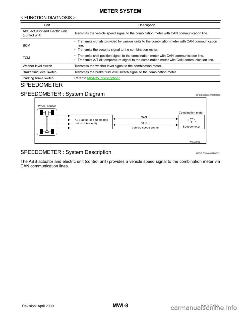
SPEEDOMETER : System DiagramINFOID:0000000005146030
SPEEDOMETER : System DescriptionINFOID:0000000005146031
The ABS actuator and electric unit (control unit) provides a vehicle speed signal to the combination meter via
CAN communication lines.
ABS actuator and electric unit
(control unit) Transmits the vehicle speed signal to the combination meter with CAN communication line.
BCM • Transmits signals provided by various units to the combination meter with CAN communication
line.
• Transmits the security signal to the combination meter.
TCM • Transmits shift position signal to the combination meter with CAN communication line.
• Transmits A/T oil temperature signal to the combination meter with CAN communication line.
Washer level switch Transmits the washer level signal to the combination meter.
Brake fluid level switch Transmits the brake fluid level switch signal to the combination meter.
Parking brake switch Refer to MWI-35, "
Description".
Unit
Description
WKIA5370E
Revision: April 20092010 QX56
Page 2782 of 4210
MWI-20
< FUNCTION DIAGNOSIS >
METER SYSTEM
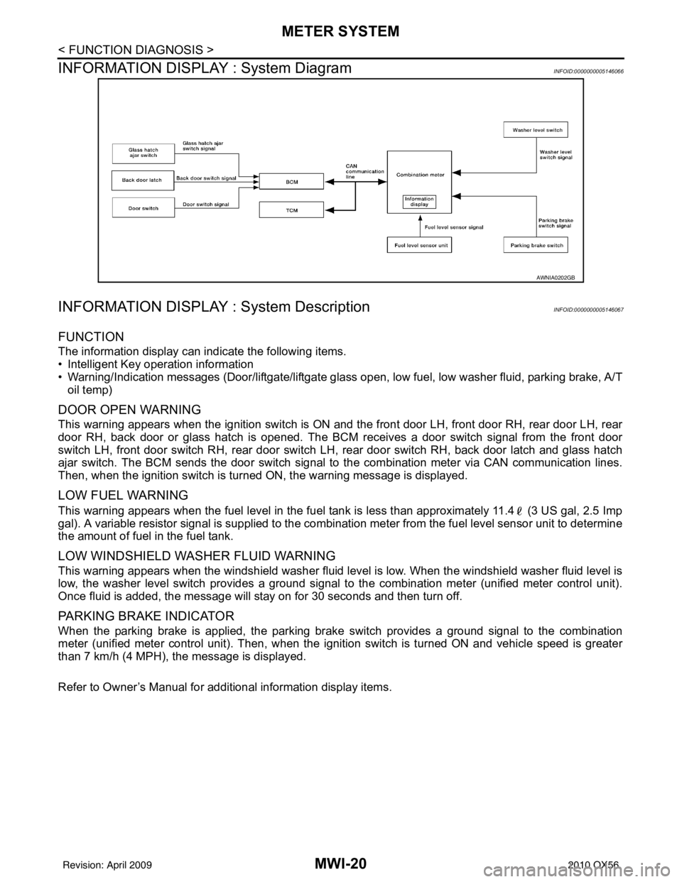
INFORMATION DISPLAY : System Diagram
INFOID:0000000005146066
INFORMATION DISPLAY : System DescriptionINFOID:0000000005146067
FUNCTION
The information display can indicate the following items.
• Intelligent Key operation information
• Warning/Indication messages (Door/liftgate/liftgate glass open, low fuel, low washer fluid, parking brake, A/T
oil temp)
DOOR OPEN WARNING
This warning appears when the ignition switch is ON and the front door LH, front door RH, rear door LH, rear
door RH, back door or glass hatch is opened. The BCM receives a door switch signal from the front door
switch LH, front door switch RH, rear door switch LH, rear door switch RH, back door latch and glass hatch
ajar switch. The BCM sends the door switch signal to the combination meter via CAN communication lines.
Then, when the ignition switch is turned ON, the warning message is displayed.
LOW FUEL WARNING
This warning appears when the fuel level in the fuel tank is less than approximately 11.4 (3 US gal, 2.5 Imp
gal). A variable resistor signal is supplied to the combination meter from the fuel level sensor unit to determine
the amount of fuel in the fuel tank.
LOW WINDSHIELD WASHER FLUID WARNING
This warning appears when the windshield washer fluid level is low. When the windshield washer fluid level is
low, the washer level switch provides a ground signal to the combination meter (unified meter control unit).
Once fluid is added, the message will stay on for 30 seconds and then turn off.
PARKING BRAKE INDICATOR
When the parking brake is applied, the parking brake switch provides a ground signal to the combination
meter (unified meter control unit). Then, when the igni tion switch is turned ON and vehicle speed is greater
than 7 km/h (4 MPH), the message is displayed.
Refer to Owner’s Manual for additional information display items.
AWNIA0202GB
Revision: April 20092010 QX56