Page 2867 of 4210
PB-4
< PREPARATION >
PREPARATION
PREPARATION
PREPARATION
Commercial Service ToolINFOID:0000000005147931
The actual shapes of Kent-Moore tools may differ from those of special service tools illustrated here.
(Kent-Moore No.)
Tool name Description
(J-21177-A)
Brake drum clearance gauge Measuring rear rotor drum to parking
brake shoe clearance
Power tool Loosening bolts and nuts
WFIA0167E
PBIC0190E
Revision: April 20092010 QX56
Page 2868 of 4210

PARKING BRAKE SYSTEMPB-5
< ON-VEHICLE MAINTENANCE >
C
DE
G H
I
J
K L
M A
B
PB
N
O P
ON-VEHICLE MAINTENANCE
PARKING BRAKE SYSTEM
On-Vehicle ServiceINFOID:0000000005147932
PEDAL STROKE
• When parking brake pedal is operated with the specified forc e, make sure the stroke is within the specified
number of notches. Check by listening and counting the ratchet clicks.
INSPECTION
• Make sure the components are attached pr operly, checking for looseness or backlash.
• Check parking brake pedal assembly for bends, damage and cracks, and replace if necessary.
• Check cable for wear and damage, and replace if necessary.
• Check parking brake warning lamp switch for malfunction, and replace if necessary. Refer to BCS-38, "
Diag-
nosis Procedure".
ADJUSTMENT
1. Remove the lower instrument panel LH. Refer to IP-14, "Exploded View".
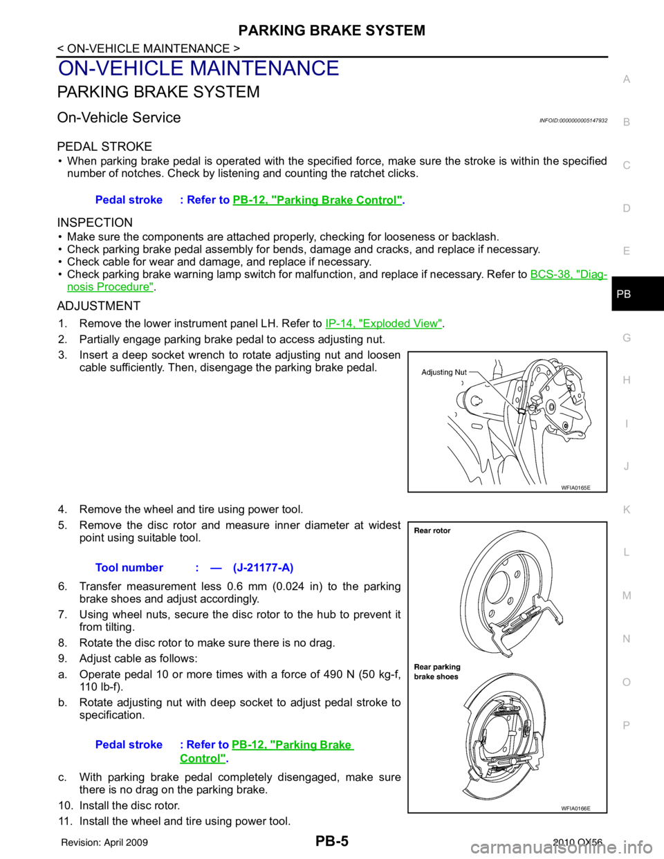
2. Partially engage parking brake pedal to access adjusting nut.
3. Insert a deep socket wrench to rotate adjusting nut and loosen cable sufficiently. Then, disengage the parking brake pedal.
4. Remove the wheel and tire using power tool.
5. Remove the disc rotor and measure inner diameter at widest point using suitable tool.
6. Transfer measurement less 0.6 mm (0.024 in) to the parking brake shoes and adjust accordingly.
7. Using wheel nuts, secure the disc rotor to the hub to prevent it from tilting.
8. Rotate the disc rotor to make sure there is no drag.
9. Adjust cable as follows:
a. Operate pedal 10 or more times with a force of 490 N (50 kg-f, 110 lb-f).
b. Rotate adjusting nut with deep socket to adjust pedal stroke to specification.
c. With parking brake pedal completely disengaged, make sure there is no drag on the parking brake.
10. Install the disc rotor.
11. Install the wheel and tire using power tool. Pedal stroke : Refer to
PB-12, "
Parking Brake Control".
WFIA0165E
Tool number : — (J-21177-A)
Pedal stroke : Refer to PB-12, "
Parking Brake
Control".
WFIA0166E
Revision: April 20092010 QX56
Page 2869 of 4210
PB-6
< ON-VEHICLE MAINTENANCE >
PARKING BRAKE SYSTEM
12. Install the lower instrument panel LH. Refer to IP-14, "Exploded View".
Revision: April 20092010 QX56
Page 2870 of 4210

PARKING BRAKE CONTROLPB-7
< ON-VEHICLE REPAIR >
C
DE
G H
I
J
K L
M A
B
PB
N
O P
ON-VEHICLE REPAIR
PARKING BRAKE CONTROL
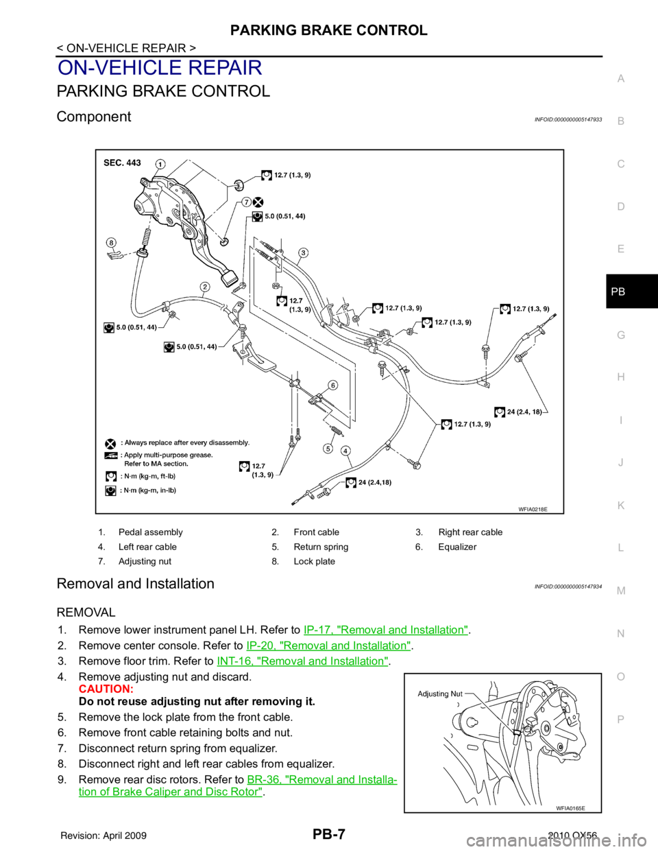
ComponentINFOID:0000000005147933
Removal and InstallationINFOID:0000000005147934
REMOVAL
1. Remove lower instrument panel LH. Refer to IP-17, "Removal and Installation".
2. Remove center console. Refer to IP-20, "
Removal and Installation".
3. Remove floor trim. Refer to INT-16, "
Removal and Installation".
4. Remove adjusting nut and discard. CAUTION:
Do not reuse adjusting nut after removing it.
5. Remove the lock plate from the front cable.
6. Remove front cable retaining bolts and nut.
7. Disconnect return spring from equalizer.
8. Disconnect right and left rear cables from equalizer.
9. Remove rear disc rotors. Refer to BR-36, "
Removal and Installa-
tion of Brake Caliper and Disc Rotor".
1. Pedal assembly 2. Front cable3. Right rear cable
4. Left rear cable 5. Return spring6. Equalizer
7. Adjusting nut 8. Lock plate
WFIA0218E
WFIA0165E
Revision: April 20092010 QX56
Page 2871 of 4210
PB-8
< ON-VEHICLE REPAIR >
PARKING BRAKE CONTROL
10. Remove parking brake shoe, and remove rear cable from toggle lever. Refer to PB-9, "Removal and
Installation".
11. Remove right and left rear cables retaining bolts and nuts, then remove right and left rear cables.
INSTALLATION
Installation is in the reverse order of removal.
• Adjust the parking brake. Refer to PB-5, "
On-Vehicle Service".
CAUTION:
Do not reuse adjusting nut after removing it.
Revision: April 20092010 QX56
Page 2872 of 4210
PARKING BRAKE SHOEPB-9
< ON-VEHICLE REPAIR >
C
DE
G H
I
J
K L
M A
B
PB
N
O P
PARKING BRAKE SHOE
Removal and InstallationINFOID:0000000005147935
COMPONENTS
REMOVAL
WARNING:
Clean the brakes with a vacuum dust co llector to minimize the hazard of airborne particles or other
materials.
NOTE:
Remove the disc rotor only with the parking brake pedal completely in the released position.
1. Remove the rear disc rotor. Refer to BR-36, "
Removal and Installation of Brake Caliper and Disc Rotor".
2. Remove the return springs.
3. Remove the adjuster.
4. Disconnect the rear cable from the toggle lever, if necessary.
• Remove pin retainer and withdraw cable end from toggle lever.
5. Remove the retainers, anti-rattle pins and shoes.
INSPECTION AFTER REMOVAL
Lining Thickness Inspection
1. Anti-rattle pins 2. Back plate3. Shoes
4. Return springs 5. Adjuster6. Retainers
7. Toggle lever
LFIA0222E
Revision: April 20092010 QX56
Page 2873 of 4210

PB-10
< ON-VEHICLE REPAIR >
PARKING BRAKE SHOE
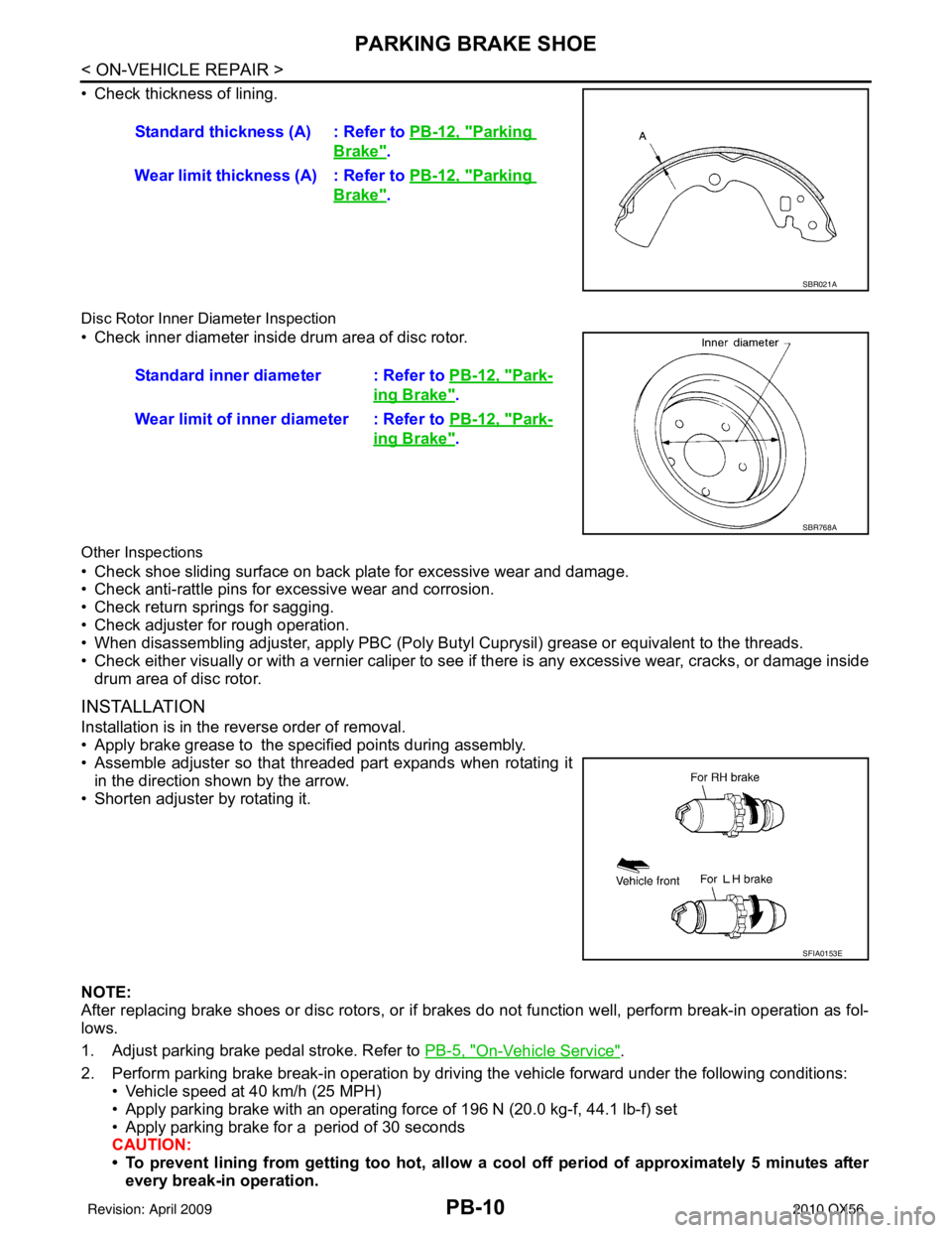
• Check thickness of lining.
Disc Rotor Inner Diameter Inspection
• Check inner diameter insi de drum area of disc rotor.
Other Inspections
• Check shoe sliding surface on back plate for excessive wear and damage.
• Check anti-rattle pins for excessive wear and corrosion.
• Check return springs for sagging.
• Check adjuster for rough operation.
• When disassembling adjuster, apply PBC (Poly Butyl Cuprysil) grease or equivalent to the threads.
• Check either visually or with a vernier caliper to see if there is any excessive wear, cracks, or damage inside
drum area of disc rotor.
INSTALLATION
Installation is in the reverse order of removal.
• Apply brake grease to the specified points during assembly.
• Assemble adjuster so that threaded part expands when rotating it
in the direction shown by the arrow.
• Shorten adjuster by rotating it.
NOTE:
After replacing brake shoes or disc rotors, or if brakes do not function well, perform break-in operation as fol-
lows.
1. Adjust parking brake pedal stroke. Refer to PB-5, "
On-Vehicle Service".
2. Perform parking brake break-in operation by driving the vehicle forward under the following conditions: • Vehicle speed at 40 km/h (25 MPH)
• Apply parking brake with an operating forc e of 196 N (20.0 kg-f, 44.1 lb-f) set
• Apply parking brake for a period of 30 seconds
CAUTION:
• To prevent lining from getting too hot, allow a cool off period of approximately 5 minutes after every break-in operation.Standard thickness (A) : Refer to
PB-12, "
Parking
Brake".
Wear limit thickness (A) : Refer to PB-12, "
Parking
Brake".
SBR021A
Standard inner diameter : Refer to PB-12, "Park-
ing Brake".
Wear limit of inner diameter : Refer to PB-12, "
Park-
ing Brake".
SBR768A
SFIA0153E
Revision: April 20092010 QX56
Page 2874 of 4210
PARKING BRAKE SHOEPB-11
< ON-VEHICLE REPAIR >
C
DE
G H
I
J
K L
M A
B
PB
N
O P
• Do not perform excessive break-in operations, because it may cause uneven or early wear of lin- ing.
3. After break-in operation, check pedal stroke of parking brake. Readjust if it is no longer at the specified stroke. Refer to PB-5, "
On-Vehicle Service".
Revision: April 20092010 QX56