2010 INFINITI QX56 brake
[x] Cancel search: brakePage 3230 of 4210

SEAT BELTSSB-13
< ON-VEHICLE REPAIR >
C
DE
F
G
I
J
K L
M A
B
SB
N
O P
2. Proceed to the designated safe area.
3. Drive the vehicle at approximately 16 km/h (10 MPH). Notify any passengers of a pending sudden stop. The driver and passenger must be prepared to brace t hemselves in the event the retractor does not lock.
Apply brakes firmly and make a very hard stop.
During stop, seat belts should lock and not be extended. If the seat belt retractor assembly does not lock, per-
form the retractor off-vehicle check.
SEAT BELT RETRACTOR OFF-VEHICLE CHECK
1. Remove the seat belt retractor assembly.
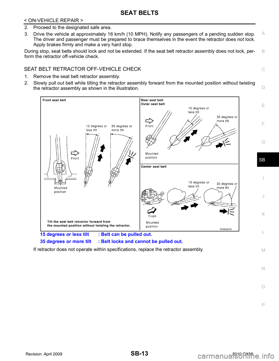
2. Slowly pull out belt while tilting the retractor asse mbly forward from the mounted position without twisting
the retractor assembly as shown in the illustration.
If retractor does not operate within specif ications, replace the retractor assembly.
15 degrees or less tilt : Belt can be pulled out.
35 degrees or more tilt : Belt locks and cannot be pulled out.
PHIA0257E
Revision: April 20092010 QX56
Page 3361 of 4210
![INFINITI QX56 2010 Factory Service Manual SEC-10
< FUNCTION DIAGNOSIS >[WITH INTELLIGENT KEY SYSTEM]
INTELLIGENT KEY SYSTEM/ENGINE START FUNCTION
FUNCTION DIAGNOSIS
INTELLIGENT KEY SYSTEM
/ENGINE START FUNCTION
System DiagramINFOID:0000000005 INFINITI QX56 2010 Factory Service Manual SEC-10
< FUNCTION DIAGNOSIS >[WITH INTELLIGENT KEY SYSTEM]
INTELLIGENT KEY SYSTEM/ENGINE START FUNCTION
FUNCTION DIAGNOSIS
INTELLIGENT KEY SYSTEM
/ENGINE START FUNCTION
System DiagramINFOID:0000000005](/manual-img/42/57032/w960_57032-3360.png)
SEC-10
< FUNCTION DIAGNOSIS >[WITH INTELLIGENT KEY SYSTEM]
INTELLIGENT KEY SYSTEM/ENGINE START FUNCTION
FUNCTION DIAGNOSIS
INTELLIGENT KEY SYSTEM
/ENGINE START FUNCTION
System DiagramINFOID:0000000005147067
System DescriptionINFOID:0000000005147068
INPUT/OUTPUT SIGNAL CHART
Intelligent Key Unit
IPDM E/R
BCM
SYSTEM DESCRIPTION
• The engine start function of Intelligent Key system is a system that makes it possible to start and stop the
engine without using the key. It verifies the electroni c ID using two-way communications when pressing the
ignition knob switch while carrying the Intelligent Key, which operates based on the results of electronic ID
verification for Intelligent Key using two-way communications between the Intelligent Key and the vehicle.
NOTE:
The driver should carry the Intelligent Key at all times.
Switch/Input signal Input signal to
Intelligent Key unit Intelligent Key unit
function Actuator/Output signal
Key switch Mechanical key
(insert/remove)
Engine start function• KEY warning lamp/buzzer
• Steering lock solenoid
• Starter relay request (to IPDM E/R)
• Inside key antenna
(Front and rear center console, over-
head console, luggage area)
• Key interlock solenoid
Ignition knob switch
Ignition knob
(push/release)
Steering lock solenoid Steering lock
(lock/unlock)
Inside key antenna
(Front and rear center console, over-
head console, luggage area) Intelligent key
(inside antenna detection
area or not.)
Switch/Input signal Input signal to
IPDM E/R IPDM E/R function
Actuator/Output signal
Transmission range switch P, N range Engine start function• Starter relay
• Starter motor
Switch/Input signal Input signal to
BCM BCM function
Actuator/Output signal
Key switch Brake
(press/release)
Engine start function• Inside key antenna
(Front and rear center console, over-
head console, luggage area)
ALKIA0925GB
Revision: April 20092010 QX56
Page 3466 of 4210
![INFINITI QX56 2010 Factory Service Manual INTELLIGENT KEY SYSTEM/ENGINE START FUNCTION SYMPTOMS
SEC-115
< SYMPTOM DIAGNOSIS > [WITH INTELLIGENT KEY SYSTEM]
C
D
E
F
G H
I
J
L
M A
B
SEC
N
O P
SYMPTOM DIAGNOSIS
INTELLIGENT KEY SYSTEM/ENGIN E STA INFINITI QX56 2010 Factory Service Manual INTELLIGENT KEY SYSTEM/ENGINE START FUNCTION SYMPTOMS
SEC-115
< SYMPTOM DIAGNOSIS > [WITH INTELLIGENT KEY SYSTEM]
C
D
E
F
G H
I
J
L
M A
B
SEC
N
O P
SYMPTOM DIAGNOSIS
INTELLIGENT KEY SYSTEM/ENGIN E STA](/manual-img/42/57032/w960_57032-3465.png)
INTELLIGENT KEY SYSTEM/ENGINE START FUNCTION SYMPTOMS
SEC-115
< SYMPTOM DIAGNOSIS > [WITH INTELLIGENT KEY SYSTEM]
C
D
E
F
G H
I
J
L
M A
B
SEC
N
O P
SYMPTOM DIAGNOSIS
INTELLIGENT KEY SYSTEM/ENGIN E START FUNCTION SYMPTOMS
Symptom TableINFOID:0000000005147148
NOTE:
• Before performing the diagnosis in the following table, check “ SEC-4, "
Work Flow"”.
• Check that vehicle is under the condition shown in “Conditions of vehicle” before starting diagnosis, and check each symptom.
• Engine cranking is enabled when the shift lever is in the "Park" position, and in the "Neutral" position only if the brake pedal is depressed.
• If the following symptoms are detec ted, check systems shown in the “Diagnosis/service procedure” column
in this order.
CONDITIONS OF VEHICLE (OPERATING CONDITIONS)
• Engine start function is ON when setting on CONSULT-III.
• Mechanical key is not inserted in key cylinder.
• One or more of Intelligent Keys with registered Intelligent Key ID is in the vehicle.
Symptom Diagnosis/service procedureReference
page
Ignition switch does not turn on with Intelligent Key.
[LCD displays "KEY DETECTED"] 1. Check steering lock solenoid.
DLK-99
2. Replace Intelligent Key unit.SEC-120
Ignition switch does not turn on with Intelligent Key.
[LCD does not display "PUSH" with arrow toward key
cylinder] 1. Check Intelligent Key unit power supply and ground circuit.
DLK-682. Check ignition knob switch.DLK-116
3. Check key switch (BCM input).DLK-115
4. Check key switch (Intelligent Key unit input).DLK-113
5. Replace Intelligent Key unit.SEC-120
Ignition switch does not turn on with Intelligent Key.
[LCD displays " NO KEY"] 1a. Check center console area antenna (rear).
DLK-60
1b. Check luggage area antenna.DLK-62
1c. Check center console area antenna (front).DLK-64
1d. Check overhead console area antenna.DLK-68
2. Replace Intelligent Key unit.SEC-120
Ignition switch does not turn on with mechanical key1. Check key switch (BCM input).
DLK-1152. Check key switch (Intelligent Key unit input).DLK-113
Engine cannot be cranked with transmission in "Park"
or in "Neutral" position with brake pedal depressed.1. Check transmission signal.
TM-45
2. Check stop lamp switch.EXL-91
Revision: April 20092010 QX56
Page 3477 of 4210

SN
INSPECTION AND ADJUSTMENTSN-5
< BASIC INSPECTION >
C
DE
F
G H
I
J
K L
M B A
O P
INSPECTION AND ADJUSTMENT
Preliminary CheckINFOID:0000000005146183
DESCRIPTION
The purpose of the sonar sensor preliminary check is to confirm that there are no outside factors affecting the
sonar system.
CONDITIONS
• Ignition switch ON
• No obstructions within 3.0 m (10 ft.) of sonar sensors
SONAR SENSOR STATUS CHECK
• Check that the sonar sensors are properly aligned (no deformation in sensor mounting areas).
• Check that snow, mud or other foreign obj ects are not adhering to the sonar sensors.
• Check that there is no deformation, scratc hes or other damage to the sonar sensors.
• Check that water has not accu mulated in the sonar sensors.
CAUTION:
Use water, cotton swab, or other soft material for cleaning the sensors.
1. Check that there are no obstacles wit hin each sonar sensor's detection range.
2. Check that there are no nearby ultrasound sources such as the sounds of vehicle horns, motorcycle
engines or truck air brakes.
3. Check that the vehicle is on a level surface.
Sonar sensors Detection range
Front Approx. 1.0 m (3 ft.) maximum
Rear Approx. 1.8 m (5.9 ft.) maximum
Revision: April 20092010 QX56
Page 3650 of 4210

ST-12
< SYMPTOM DIAGNOSIS >
NOISE, VIBRATION AND HARSHNESS (NVH) TROUBLESHOOTING
SYMPTOM DIAGNOSIS
NOISE, VIBRATION AND HARSHNESS (NVH) TROUBLESHOOTING
NVH Troubleshooting ChartINFOID:0000000005147864
Use chart below to help you find the cause of the symp tom. If necessary, repair or replace these parts.
×: ApplicableReference page
ST-13, "
Checking Fluid Level
"
ST-13, "
Air Bleeding Hydraulic System
"
ST-36ST-36ST-36ST-13ST-35ST-37
EM-13, "
Checking Drive Belts
"
ST-35ST-35ST-37ST-35ST-20ST-37
DLN-184, "
NVH Troubleshooting Chart
"
DLN-208, "
NVH Troubleshooting Chart
"
FAX-5, "
NVH Troubleshooting Chart
"
FSU-5, "
NVH Troubleshooting Chart
"
WT-43, "
NVH Troubleshooting Chart
"
WT-43, "
NVH Troubleshooting Chart
"
FAX-5, "
NVH Troubleshooting Chart
"
BR-6, "
NVH Troubleshooting Chart
"
Possible cause and suspect-
ed parts
Fluid level
Air in hydraulic system
Outer socket ball joint swinging force
Outer socket ball joint rotating torque
Outer socket ball joint end play
Steering fluid leakage
Steering wheel play
Steering gear rack sliding force
Drive belt looseness
Improper steering wheel
Improper installation or looseness of tilt lock lever
Mounting rubber deterioration
Steering column deformation or damage
Improper installation or looseness of steering column
Steering linkage looseness
PROPELLER SHAFT
FRONT FINAL DRIVE
WHEEL HUB
SUSPENSION
TIRES
ROAD WHEEL
DRIVE SHAFT
BRAKES
Symptom
Noise
× × ××××× × × ××××××× ×
Shake ×××× ××××× ×
Vibration ××××× × ××× ×
Shimmy ××× × ×××× ×
Shudder × × ×××× ×
Revision: April 20092010 QX56
Page 3653 of 4210

STEERING WHEELST-15
< ON-VEHICLE REPAIR >
C
DE
F
H I
J
K L
M A
B
ST
N
O P
ON-VEHICLE REPAIR
STEERING WHEEL
On-Vehicle Inspection and ServiceINFOID:0000000005147868
CHECKING CONDITION OF INSTALLATION
• Check installation condition of steering gear assembly, front suspension, axle and steering column.
• Check if movement exists when steering wheel is mo ved up and down, to the left and right and to the axial
direction.
• Check if the nuts for steering gear assembly are loose. Refer to ST-23, "
Removal and Installation".
CHECKING STEERING WHEEL PLAY
1. Turn tires straight ahead, start engine, then turn steer ing wheel to the left and right lightly, and measure
steering wheel movement on the outer circumference when steering wheel is turned up to the point where
tires start moving.
CHECKING NEUTRAL POSITION ON STEERING WHEEL
• Check neutral position on steering wheel after confirming that front wheel alignment is correct. Refer to FSU-
6, "Front Wheel Alignment".
1. Turn tires straight ahead, check if steering wheel is in the neutral position.
2. If it is not in the neutral position, remo ve steering wheel and reinstall it correctly.
3. If the neutral position cannot be attained by repositi oning the steering wheel two teeth or less on steering
stem, loosen tie-rod lock nuts of steering outer socket s, then adjust tie-rods by the same amount in the
opposite direction.
CHECKING STEERING WHEEL TURNING FORCE
1. Park vehicle on a level, dry surface and set parking brake.
2. Start engine.
3. Bring power steering fluid up to operating temperature of 60 °– 80° C (140° – 176°F).
4. Tires need to be inflated to specified pressure. Refer to WT-52, "
Tire".
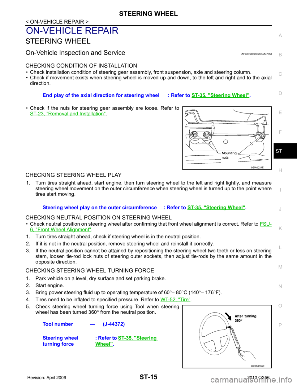
5. Check steering wheel turning force using Tool when steering wheel has been turned 360 ° from the neutral position.
End play of the axial direction for steering wheel : Refer to
ST-35, "
Steering Wheel".
LGIA0024E
Steering wheel play on the outer circumference : Refer to ST-35, "Steering Wheel".
Tool number — (J-44372)
Steering wheel
turning force : Refer to
ST-35, "
Steering
Wheel".
WGIA0035E
Revision: April 20092010 QX56
Page 3696 of 4210

TM-1
TRANSMISSION & DRIVELINE
CEF
G H
I
J
K L
M
SECTION TM
A
B
TM
N
O P
CONTENTS
TRANSAXLE & TRANSMISSION
BASIC INSPECTION ....... .............................5
DIAGNOSIS AND REPAIR WORKFLOW ..... .....5
Work Flow ........................................................... ......5
Diagnostic Work Sheet ..............................................6
FUNCTION DIAGNOSIS ...............................8
A/T CONTROL SYSTEM ................................ .....8
Cross-Sectional View (2WD models) .................. ......8
Cross-Sectional View (4WD models) ........................9
Shift Mechanism ........................................................9
TCM Function ..........................................................20
CAN Communication ...............................................21
Input/Output Signal of TCM .....................................22
Line Pressure Control .............................................22
Shift Control ........................................................ ....24
Lock-up Control .......................................................25
Engine Brake Control ..............................................26
Control Valve ...........................................................26
Component Parts Location ......................................28
A/T SHIFT LOCK SYSTEM ............................ ....29
System Description ............................................. ....29
Component Parts Location ......................................29
ON BOARD DIAGNOSTIC (OBD) SYSTEM ......30
Introduction ......................................................... ....30
OBD-II Function for A/T System ..............................30
One or Two Trip Detection Logic of OBD-II ............30
OBD-II Diagnostic Trouble Code (DTC) ..................30
Malfunction Indicator Lamp (MIL) ............................31
DIAGNOSIS SYSTEM (TCM) .............................32
CONSULT-III Function (TRANSMISSION) ......... ....32
Diagnosis Procedure without CONSULT-III ........ ....37
COMPONENT DIAGNOSIS .........................40
U1000 CAN COMM CI RCUIT .............................40
Description .......................................................... ....40
On Board Diagnosis Logic ......................................40
Possible Cause .................................................... ....40
DTC Confirmation Procedure ..................................40
Diagnosis Procedure ...............................................40
P0615 STARTER RELAY .................................41
Description ...............................................................41
CONSULT-III Reference Value in Data Monitor
Mode .................................................................... ....
41
On Board Diagnosis Logic .......................................41
Possible Cause ........................................................41
DTC Confirmation Procedure ..................................41
Diagnosis Procedure ...............................................41
P0700 TRANSMISSION CONTROL .................44
Description ...............................................................44
On Board Diagnosis Logic .......................................44
Possible Cause ........................................................44
DTC Confirmation Procedure ..................................44
Diagnosis Procedure ...............................................44
P0705 TRANSMISSION RANGE SWITCH A ...45
Description ...............................................................45
CONSULT-III Reference Value in Data Monitor
Mode .................................................................... ....
45
On Board Diagnosis Logic .......................................45
Possible Cause ........................................................45
DTC Confirmation Procedure ..................................45
Diagnosis Procedure ...............................................45
P0717 INPUT SPEED SENSOR A ....................48
Description ...............................................................48
CONSULT-III Reference Value in Data Monitor
Mode .................................................................... ....
48
On Board Diagnosis Logic .......................................48
Possible Cause ........................................................48
DTC Confirmation Procedure ..................................48
Diagnosis Procedure ...............................................48
P0720 OUTPUT SPEED SENSOR ...................50
Description ...............................................................50
CONSULT-III Reference Value in Data Monitor
Mode .................................................................... ....
50
Revision: April 20092010 QX56
Page 3698 of 4210

TM-3
CEF
G H
I
J
K L
M A
B
TM
N
O P
Diagnosis Procedure ...........................................
....
80
P1752 INPUT CLUTCH SOLENOID ..................82
Description .......................................................... ....82
CONSULT-III Reference Value in Data Monitor
Mode ................................................................... ....
82
On Board Diagnosis Logic ......................................82
Possible Cause .......................................................82
DTC Confirmation Procedure ..................................82
Diagnosis Procedure ...............................................82
P1757 FRONT BRAKE SOLENOID ...................84
Description .......................................................... ....84
CONSULT-III Reference Value in Data Monitor
Mode ................................................................... ....
84
On Board Diagnosis Logic ......................................84
Possible Cause .......................................................84
DTC Confirmation Procedure ..................................84
Diagnosis Procedure ...............................................84
P1762 DIRECT CLUTCH SOLENOID ................86
Description .......................................................... ....86
CONSULT-III Reference Value in Data Monitor
Mode ................................................................... ....
86
On Board Diagnosis Logic ......................................86
Possible Cause .......................................................86
DTC Confirmation Procedure ..................................86
Diagnosis Procedure ...............................................86
P1767 HIGH AND LOW REVERSE CLUTCH
SOLENOID .........................................................
88
Description .......................................................... ....88
CONSULT-III Reference Value in Data Monitor
Mode ................................................................... ....
88
On Board Diagnosis Logic ......................................88
Possible Cause .......................................................88
DTC Confirmation Procedure ..................................88
Diagnosis Procedure ...............................................88
P1772 LOW COAST BRAKE SOLENOID .........90
Description .......................................................... ....90
CONSULT-III Reference Value in Data Monitor
Mode ................................................................... ....
90
On Board Diagnosis Logic ......................................90
Possible Cause .......................................................90
DTC Confirmation Procedure ..................................90
Diagnosis Procedure ...............................................90
P1774 LOW COAST BRAKE SOLENOID .........92
Description .......................................................... ....92
CONSULT-III Reference Value in Data Monitor
Mode ................................................................... ....
92
On Board Diagnosis Logic ......................................92
Possible Cause .......................................................92
DTC Confirmation Procedure ..................................92
Diagnosis Procedure ...............................................93
MAIN POWER SUPPLY AND GROUND CIR-
CUIT ....................................................................
94
Diagnosis Procedure ........................................... ....94
CLOSED THROTTLE POSITION AND WIDE
OPEN THROTTLE POSITION CIRCUIT ...........
96
CONSULT-III Reference Value in Data Monitor
Mode .................................................................... ....
96
Diagnosis Procedure ...............................................96
BRAKE SIGNAL CIRCUIT ................................97
CONSULT-III Reference Va lue in Data Monitor
Mode .................................................................... ....
97
Diagnosis Procedure ...............................................97
TOW MODE SWITCH .......................................98
Description ...............................................................98
Diagnosis Procedure ...............................................98
A/T SHIFT LOCK SYSTEM ...............................99
Description ...............................................................99
Terminals And Reference Values ............................99
Wiring Diagram - A/T SH IFT LOCK SYSTEM - .....100
Component Inspection ......................................... ..103
ECU DIAGNOSIS .......................................106
TCM .................................................................106
Reference Value .................................................. ..106
Wiring Diagram — A/T CONTROL SYSTEM — .. ..108
Fail-Safe .............................................................. ..117
DTC Inspection Priority Chart ................................119
DTC No. Index .......................................................119
DTC Alphabetical Index .........................................120
SYMPTOM DIAGNOSIS ............................121
SYSTEM SYMPTOM .......................................121
Symptom Table ................................................... ..121
PRECAUTION ............................................143
PRECAUTIONS ...............................................143
Precaution for Supplemental Restraint System
(SRS) "AIR BAG" and "SEAT BELT PRE-TEN-
SIONER" ............................................................. ..
143
Precaution for On Board Diagnosis (OBD) System
of A/T and Engine ................................................ ..
143
Precaution .............................................................143
Service Notice or Precaution .................................144
PREPARATION .........................................146
PREPARATION ...............................................146
Special Service Tool ............................................ ..146
Commercial Service Tool ......................................147
ON-VEHICLE MAINTENANCE ..................148
A/T FLUID .......................................................148
Checking the A/T Fluid (ATF) .............................. ..148
Changing the A/T Fluid (ATF) ................................150
A/T FLUID COOLER .......................................152
A/T Fluid Cooler Cleaning .....................................152
Inspection ..............................................................154
Revision: April 20092010 QX56