Page 1996 of 4210

EXL-20
< FUNCTION DIAGNOSIS >
DIAGNOSIS SYSTEM (BCM)
FLASHER
FLASHER : CONSULT-III Function (BCM - FLASHER)INFOID:0000000005369884
DATA MONITOR
ACTIVE TEST
COMB SW
COMB SW : CONSULT-III Function (BCM - COMB SW)INFOID:0000000005369885
DATA MONITOR
Test ItemOperation Description
TA I L L A M P ON
Transmits the position light reques
t signal to IPDM E/R with CAN com-
munication to turn the tail lamp ON.
OFF Stops the tail lamp request signal transmission.
HEAD LAMP HI
Transmits the high beam request signal with CAN communication to turn
the headlamp (HI).
LO Transmits the low beam request signal with CAN communication to turn
the headlamp (LO).
OFF Stops the high & low beam request signal transmission.
FR FOG LAMP ON
Transmits the front fog lights request signal to IPDM E/R with CAN com-
munication to turn the front fog lamp ON.
OFF Stops the front fog lights request signal transmission.
CARGO LAMP ON
Transmits the cargo lamp request signal with CAN communication to
turn the lamp ON.
OFF Stops the cargo lamp request signal transmission.
CORNERING LAMP LH
Transmits the LH cornering lamp request signal with CAN communica-
tion to turn the lamp ON.
RH Transmits the RH cornering lamp request signal with CAN communica-
tion to turn the lamp ON.
OFF Stops the day time running light request signal transmission.
Monitor Item [Unit] Description
IGN ON SW [ON/OFF] Ignition switch (ON) status judged from IGN signal (ignition power supply)
HAZARD SW [ON/OFF] The switch status input from the hazard switch
TURN SIGNAL R [ON/OFF] Each switch condition that BCM judges from the combination switch reading function
TURN SIGNAL L [ON/OFF]
BRAKE SW [ON/OFF] The switch status input from the brake switch
Test ItemOperation Description
FLASHER RH Outputs the voltage to turn the right side turn signal lamps ON.
LH Outputs the voltage to turn the left side turn signal lamps ON.
OFF Stops the voltage to turn the turn signal lamps OFF.
Revision: April 20092010 QX56
Page 2113 of 4210
EXTERIOR LIGHTING SYSTEM SYMPTOMSEXL-137
< SYMPTOM DIAGNOSIS >
C
DE
F
G H
I
J
K
M A
B
EXL
N
O P
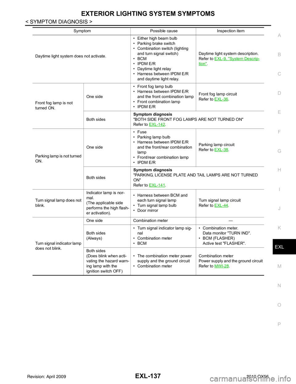
Daytime light system does not activate. • Either high beam bulb
• Parking brake switch
• Combination switch (lighting
and turn signal switch)
•BCM
• IPDM E/R
• Daytime light relay
• Harness between IPDM E/R
and daytime light relay. Daytime light system description.
Refer to
EXL-9, "System Descrip-
tion".
Front fog lamp is not
turned ON. One side
• Front fog lamp bulb
• Harness between IPDM E/R
and the front combination lamp
• Front combination lamp
• IPDM E/R Front fog lamp circuit
Refer to
EXL-36
.
Both sides Symptom diagnosis
"BOTH SIDE FRONT FOG LAMPS ARE NOT TURNED ON"
Refer to EXL-142
.
Parking lamp is not turned
ON. One side•Fuse
• Parking lamp bulb
• Harness between IPDM E/R
and the front/rear combination
lamp
• Front/rear combination lamp
• IPDM E/R Parking lamp circuit
Refer to
EXL-38
.
Both sides Symptom diagnosis
"PARKING, LICENSE PLATE AND TAIL LAMPS ARE NOT TURNED
ON"
Refer to EXL-141
.
Turn signal lamp does not
blink. Indicator lamp is nor-
mal.
(The applicable side
performs the high flash-
er activation).• Harness between BCM and
each turn signal lamp
• Turn signal lamp bulb
• Door mirror Turn signal lamp circuit
Refer to
EXL-44
.
Turn signal indicator lamp
does not blink. One side
Combination meter —
Both sides
(Always) • Turn signal indicator lamp sig-
nal
• Combination meter
•BCM • Combination meter.
Data monitor "TURN IND".
• BCM (FLASHER) Active test "FLASHER".
Both sides
(Does blink when acti-
vating the hazard warn-
ing lamp with the
ignition switch OFF) • The combination meter power
supply and the ground circuit
• Combination meter Combination meter
Power supply and the ground circuit
Refer to
MWI-28
.
Symptom
Possible causeInspection item
Revision: April 20092010 QX56
Page 2120 of 4210

EXL-144
< PRECAUTION >
PRECAUTIONS
5. When the repair work is completed, re-connect both battery cables. With the brake pedal released, turn
the push-button ignition switch from ACC position to ON position, then to LOCK position. (The steering
wheel will lock when the push-button igniti on switch is turned to LOCK position.)
6. Perform self-diagnosis check of all control units using CONSULT-III.
General precautions for service operationsINFOID:0000000005369811
• When removing or disassembling any part, be careful not to damage or deform it. Protect parts which may
get in the way with cloth.
• When removing parts with a screw driver or other tool , protect parts by wrapping them with vinyl or tape.
• Keep removed parts protected with cloth.
• If an non-reuseable part is removed, replace it with a new one.
• After re-assembly has been completed, make sure each part functions correctly.
• Never work with wet hands.
• Turn the combination switch (lighting and turn signal switch) OFF before disconnecting and connecting the connector.
• Do not use organic solvent (paint thinner or gasoline) to clean lamps or remove sealant residue.
Revision: April 20092010 QX56
Page 2171 of 4210
NOISE, VIBRATION AND HARSHNESS (NVH) TROUBLESHOOTINGFAX-5
< SYMPTOM DIAGNOSIS >
CEF
G H
I
J
K L
M A
B
FA X
N
O P
SYMPTOM DIAGNOSIS
NOISE, VIBRATION AND HARSHN ESS (NVH) TROUBLESHOOTING
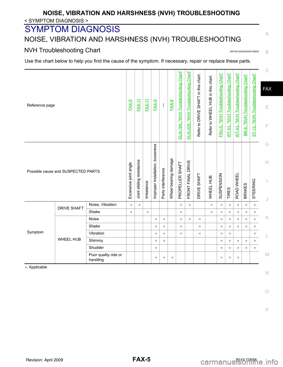
NVH Troubleshooting ChartINFOID:0000000005148942
Use the chart below to help you find t he cause of the symptom. If necessary, repair or replace these parts.
×: ApplicableReference page
FA X - 9FA X - 11FA X - 11FA X - 9—
FA X - 6
DLN-184, "
NVH Troubleshooting Chart
"
DLN-208, "
NVH Troubleshooting Chart
"
Refer to DRIVE SHAFT in this chart.
Refer to WHEEL HUB in this chart.
FSU-5, "
NVH Troubleshooting Chart
"
WT-43, "
NVH Troubleshooting Chart
"
WT-43, "
NVH Troubleshooting Chart
"
BR-6, "
NVH Troubleshooting Chart
"
ST-12, "
NVH Troubleshooting Chart
"
Possible cause and SUSPECTED PARTS
Excessive joint angle
Joint sliding resistance
Imbalance
Improper installation, looseness
Parts interference
Wheel bearing damage
PROPELLER SHAFT
FRONT FINAL DRIVE
DRIVE SHAFT
WHEEL HUB
SUSPENSION
TIRES
ROAD WHEEL
BRAKES
STEERING
Symptom DRIVE SHAFT
Noise, Vibration
×× × × × ×××× ×
Shake × × ×× ×××× ×
WHEEL HUB Noise
×× × × × ×××× ×
Shake ×× × × ×××× ×
Vibration ×× × × ×× ×
Shimmy ×××××× ×
Shudder ×× ××× ×
Poor quality ride or
handling ×××
×××
Revision: April 20092010 QX56
Page 2173 of 4210
WHEEL HUBFAX-7
< REMOVAL AND INSTALLATION >
CEF
G H
I
J
K L
M A
B
FA X
N
O P
REMOVAL AND INSTALLATION
WHEEL HUB
Removal and InstallationINFOID:0000000005148944
REMOVAL
1. Remove wheel and tire using power tool.
2. Remove engine under cover using power tool.
3. Without disassembling the hydraulic lines, remove caliper torque member bolts using power tool. Then
reposition brake caliper aside with wire. Refer to BR-31, "
Removal and Installation of Brake Caliper and
Rotor" .
NOTE:
Do not press brake pedal while brake caliper is removed.
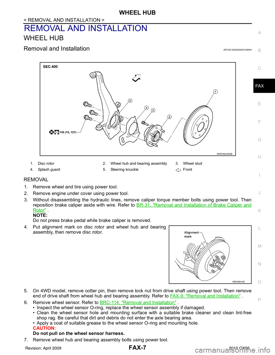
4. Put alignment mark on disc rotor and wheel hub and bearing assembly, then remove disc rotor.
5. On 4WD model, remove cotter pin, then remove lock nut from drive shaft using power tool. Then remove end of drive shaft from wheel hub and bearing assembly. Refer to FAX-9, "
Removal and Installation" .
6. Remove wheel sensor. Refer to BRC-114, "
Removal and Installation" .
• Inspect the wheel sensor O-ring, replac e the wheel sensor assembly if damaged.
• Clean the wheel sensor hole and mounting surface with a suitable brake cleaner and clean lint-free shop rag. Be careful that dirt and debris do not enter the axle bearing area.
• Apply a coat of suitable grease to the wheel sensor O-ring and mounting hole.
CAUTION:
Do not pull on the wheel sensor harness.
7. Remove wheel hub and bearing assembly bolts using power tool.
1. Disc rotor 2. Wheel hub and bearing assembly 3. Wheel stud
4. Splash guard 5. Steering knuckle Front
AWDIA0423GB
WDIA0044E
Revision: April 20092010 QX56
Page 2174 of 4210
FAX-8
< REMOVAL AND INSTALLATION >
WHEEL HUB
8. Remove splash guard and wheel hub and bearing assembly from steering knuckle.
INSPECTION AFTER REMOVAL
Check for deformity, cracks and damage on each part, replace if necessary.
INSTALLATION
Installation is in the reverse order of removal.
• Use new bolts when installing the wheel hub and bearing assembly.
• When installing disc rotor on wheel hub and bearing assembly,
position the disc rotor according to alignment mark.
(When not using the alignment mark, refer to BR-31, "
Removal
and Installation of Brake Caliper and Rotor" .)
• When installing wheel and tire. Refer to WT-49, "
Rotation" .
WDIA0044E
Revision: April 20092010 QX56
Page 2175 of 4210
DRIVE SHAFTFAX-9
< REMOVAL AND INSTALLATION >
CEF
G H
I
J
K L
M A
B
FA X
N
O P
DRIVE SHAFT
Removal and InstallationINFOID:0000000005148945
REMOVAL
1. Remove wheel and tire using power tool.
2. Remove engine under cover using power tool.
3. Remove wheel sensor harness from mount on knuckle and reposition aside. Refer to BRC-114, "
Removal
and Installation".
CAUTION:
Do not pull on wheel sensor harness.
4. Without disassembling the hydraulic lines, remove brake caliper using power tool. Reposition it aside with wire. Refer to BR-31, "
Removal and Installation of Brake Caliper and Rotor" .
NOTE:
Avoid depressing brake pedal while brake caliper is removed.
5. Remove coil spring and shock absorber assembly using power tool. Refer to FSU-14, "
Removal and
Installation" .
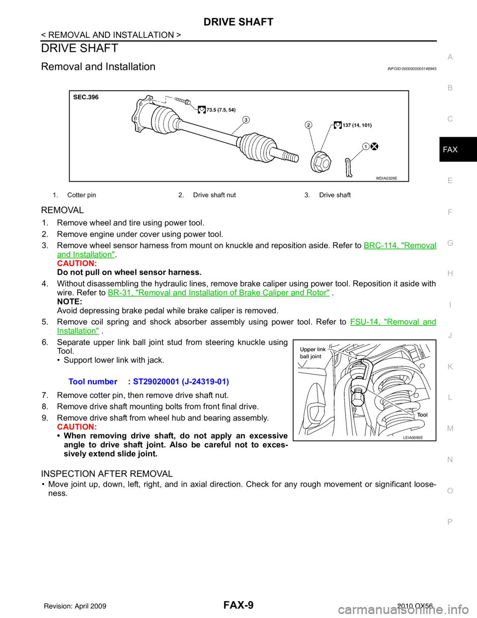
6. Separate upper link ball joint stud from steering knuckle using Tool.
• Support lower link with jack.
7. Remove cotter pin, then remove drive shaft nut.
8. Remove drive shaft mounting bolts from front final drive.
9. Remove drive shaft from wheel hub and bearing assembly. CAUTION:
• When removing drive shaf t, do not apply an excessive
angle to drive shaft joint. Also be careful not to exces-
sively extend slide joint.
INSPECTION AFTER REMOVAL
• Move joint up, down, left, right, and in axial directi on. Check for any rough movement or significant loose-
ness.
1. Cotter pin 2. Drive shaft nut3. Drive shaft
WDIA0329E
Tool number : ST29020001 (J-24319-01)
LEIA0095E
Revision: April 20092010 QX56
Page 2204 of 4210
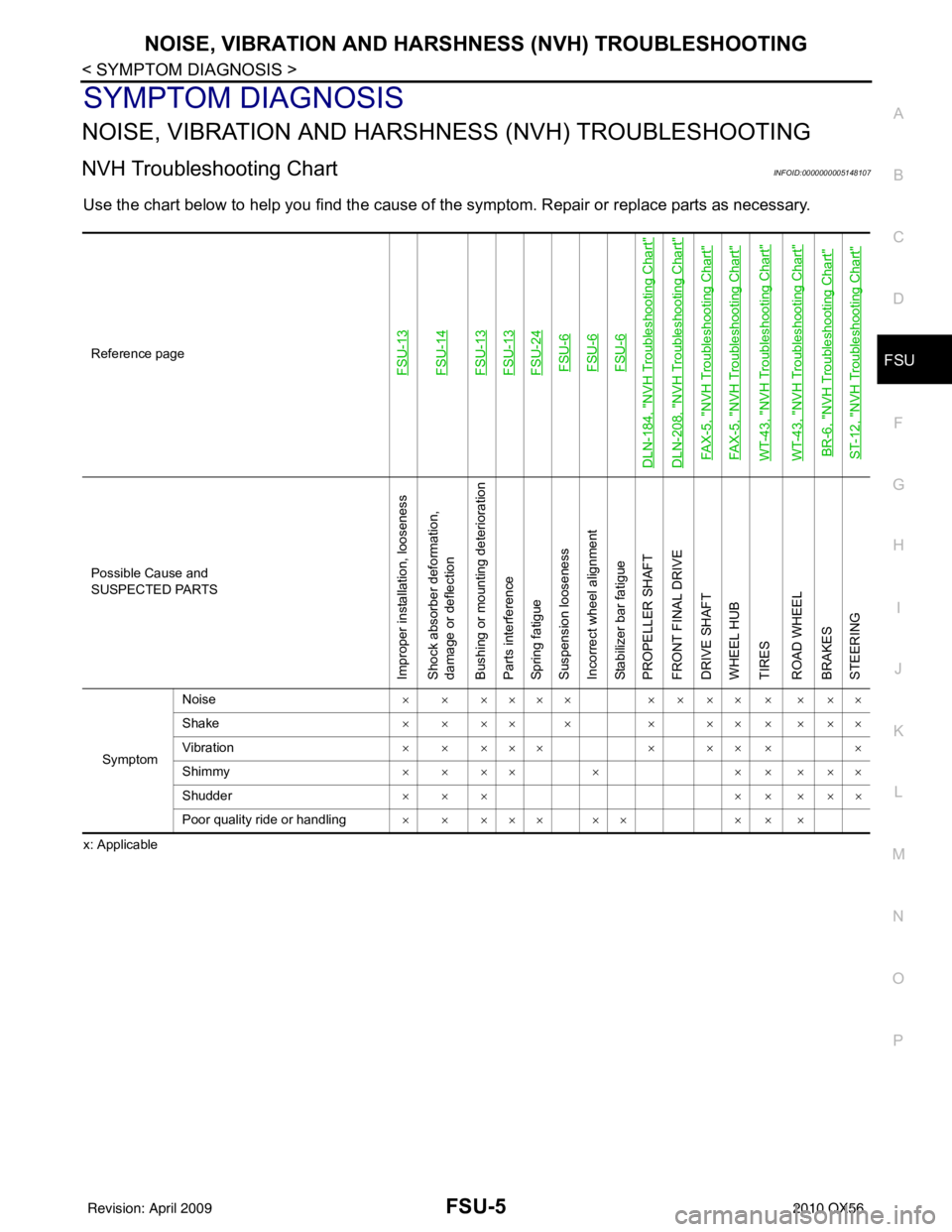
NOISE, VIBRATION AND HARSHNESS (NVH) TROUBLESHOOTINGFSU-5
< SYMPTOM DIAGNOSIS >
C
DF
G H
I
J
K L
M A
B
FSU
N
O P
SYMPTOM DIAGNOSIS
NOISE, VIBRATION AND HARSHN ESS (NVH) TROUBLESHOOTING
NVH Troubleshooting ChartINFOID:0000000005148107
Use the chart below to help you find the cause of the symptom. Repair or replace parts as necessary.
x: ApplicableReference page
FSU-13FSU-14FSU-13FSU-13FSU-24FSU-6FSU-6FSU-6
DLN-184, "
NVH Troubleshooting Chart
"
DLN-208, "
NVH Troubleshooting Chart
"
FAX-5, "
NVH Troubleshooting Chart
"
FAX-5, "
NVH Troubleshooting Chart
"
WT-43, "
NVH Troubleshooting Chart
"
WT-43, "
NVH Troubleshooting Chart
"
BR-6, "
NVH Troubleshooting Chart
"
ST-12, "
NVH Troubleshooting Chart
"
Possible Cause and
SUSPECTED PARTS
Improper installation, looseness
Shock absorber deformation,
damage or deflection
Bushing or mounting deterioration
Parts interference
Spring fatigue
Suspension looseness
Incorrect wheel alignment
Stabilizer bar fatigue
PROPELLER SHAFT
FRONT FINAL DRIVE
DRIVE SHAFT
WHEEL HUB
TIRES
ROAD WHEEL
BRAKES
STEERING
Symptom
Noise
× × ×××× × × ×× × × ××
Shake × × ×× × × ×× × × ××
Vibration × × ××× × ×× × ×
Shimmy × × ×× × × × × ××
Shudder ××× ×××××
Poor quality ride or handling × × ××× ×× × × ×
Revision: April 20092010 QX56