2010 INFINITI QX56 battery location
[x] Cancel search: battery locationPage 1630 of 4210
![INFINITI QX56 2010 Factory Service Manual P0506 ISC SYSTEMEC-277
< COMPONENT DIAGNOSIS > [VK56DE]
C
D
E
F
G H
I
J
K L
M A
EC
NP
O
P0506 ISC SYSTEM
DescriptionINFOID:0000000005149303
NOTE:
If DTC P0506 is displayed with ot
her DTC, first perfo INFINITI QX56 2010 Factory Service Manual P0506 ISC SYSTEMEC-277
< COMPONENT DIAGNOSIS > [VK56DE]
C
D
E
F
G H
I
J
K L
M A
EC
NP
O
P0506 ISC SYSTEM
DescriptionINFOID:0000000005149303
NOTE:
If DTC P0506 is displayed with ot
her DTC, first perfo](/manual-img/42/57032/w960_57032-1629.png)
P0506 ISC SYSTEMEC-277
< COMPONENT DIAGNOSIS > [VK56DE]
C
D
E
F
G H
I
J
K L
M A
EC
NP
O
P0506 ISC SYSTEM
DescriptionINFOID:0000000005149303
NOTE:
If DTC P0506 is displayed with ot
her DTC, first perform the trouble diagnosis for the other DTC.
The ECM controls the engine idle speed to a specified level through the fine adjustment of the air, which is let
into the intake manifold, by operating the electric thrott le control actuator. The operating of the throttle valve is
varied to allow for optimum control of the engine idli ng speed. The crankshaft position sensor (POS) detects
the actual engine speed and sends a signal to the ECM.
The ECM controls the electric throttle control actuator so that the engine speed coincides with the target value
memorized in the ECM. The target engine speed is the lowest speed at which the engine can operate steadily.
The optimum value stored in the ECM is determined by taking into consideration various engine conditions,
such as during warming up, deceleration, and engine load (air conditioner, power steering and cooling fan
operation, etc.).
On Board Diagnosis LogicINFOID:0000000005149304
DTC Confirmation ProcedureINFOID:0000000005149305
NOTE:
• If DTC Confirmation Procedure has been previously conducted, always perform the following procedure before conducting the next step.
1. Turn ignition switch OFF and wait at least 10 seconds.
2. Turn ignition switch ON.
3. Turn ignition switch OFF and wait at least 10 seconds.
• If the target idle speed is ou t of the specified value, perform EC-18, "
Idle Air Volume Learning",
before conducting DTC Confirmation Procedure. For the target idle speed, refer to the EC-497, "
Idle
Speed and Ignition Timing".
TESTING CONDITION:
• Before performing the following procedure, confirm that battery voltage is more than 11V at idle.
• Always perform the test at a temperature above −10° C (14° F).
1. Open engine hood.
2. Start engine and warm it up to normal operating temperature.
3. Turn ignition switch OFF and wait at least 10 seconds.
4. Start engine and run it for at least 1 minute at idle speed.
5. Check 1st trip DTC.
6. If 1st trip DTC is detected, go to EC-277, "
Diagnosis Procedure".
Diagnosis ProcedureINFOID:0000000005149306
1.CHECK INTAKE AIR LEAK
1. Start engine and let it idle.
2. Listen for an intake air leak after the mass air flow sensor.
OK or NG
OK >> GO TO 2.
NG >> Discover air leak location and repair.
2.REPLACE ECM
1. Stop engine.
2. Replace ECM.
3. Perform initialization of IVIS(NATS) system and registration of all IVIS(NATS) ignition key IDs. Refer to SEC-9, "
ECM RE-COMMUNICATING FUNCTION : Special Repair Requirement".
4. Perform EC-17, "
VIN Registration".
5. Perform EC-18, "
Accelerator Pedal Released Position Learning".
DTC No. Trouble diagnosis name DTC detecting conditionPossible cause
P0506
0506 Idle speed control system
RPM lower than expected The idle speed is less than the target idle speed
by 100 rpm or more. • Electric throttle control actuator
• Intake air leak
Revision: April 20092010 QX56
Page 1632 of 4210
![INFINITI QX56 2010 Factory Service Manual P0507 ISC SYSTEMEC-279
< COMPONENT DIAGNOSIS > [VK56DE]
C
D
E
F
G H
I
J
K L
M A
EC
NP
O
P0507 ISC SYSTEM
DescriptionINFOID:0000000005149307
NOTE:
If DTC P0507 is displayed with ot
her DTC, first perfo INFINITI QX56 2010 Factory Service Manual P0507 ISC SYSTEMEC-279
< COMPONENT DIAGNOSIS > [VK56DE]
C
D
E
F
G H
I
J
K L
M A
EC
NP
O
P0507 ISC SYSTEM
DescriptionINFOID:0000000005149307
NOTE:
If DTC P0507 is displayed with ot
her DTC, first perfo](/manual-img/42/57032/w960_57032-1631.png)
P0507 ISC SYSTEMEC-279
< COMPONENT DIAGNOSIS > [VK56DE]
C
D
E
F
G H
I
J
K L
M A
EC
NP
O
P0507 ISC SYSTEM
DescriptionINFOID:0000000005149307
NOTE:
If DTC P0507 is displayed with ot
her DTC, first perform the trouble diagnosis for the other DTC.
The ECM controls the engine idle speed to a specified level through the fine adjustment of the air, which is let
into the intake manifold, by operating the electric thrott le control actuator. The operating of the throttle valve is
varied to allow for optimum control of the engine idli ng speed. The crankshaft position sensor (POS) detects
the actual engine speed and sends a signal to the ECM.
The ECM controls the electric throttle control actuator so that the engine speed coincides with the target value
memorized in the ECM. The target engine speed is the lowest speed at which the engine can operate steadily.
The optimum value stored in the ECM is determined by taking into consideration various engine conditions,
such as during warming up, deceleration, and engine load (air conditioner, power steering and cooling fan
operation, etc.).
On Board Diagnosis LogicINFOID:0000000005149308
DTC Confirmation ProcedureINFOID:0000000005149309
NOTE:
• If DTC Confirmation Procedure has been previously conducted, always perform the following procedure before conducting the next step.
1. Turn ignition switch OFF and wait at least 10 seconds.
2. Turn ignition switch ON.
3. Turn ignition switch OFF and wait at least 10 seconds.
• If the target idle speed is ou t of the specified value, perform EC-18, "
Idle Air Volume Learning",
before conducting DTC Confirmation Procedure. For the target idle speed, refer to the EC-497, "
Idle
Speed and Ignition Timing".
TESTING CONDITION:
• Before performing the following procedure, confirm that battery voltage is more than 11V at idle.
• Always perform the test at a temperature above −10° C (14° F).
1. Open engine hood.
2. Start engine and warm it up to normal operating temperature.
3. Turn ignition switch OFF and wait at least 10 seconds.
4. Start engine and run it for at least 1 minute at idle speed.
5. Check 1st trip DTC.
6. If 1st trip DTC is detected, go to EC-279, "
Diagnosis Procedure".
Diagnosis ProcedureINFOID:0000000005149310
1.CHECK PCV HOSE CONNECTION
Confirm that PCV hose is connected correctly.
OK or NG
OK >> GO TO 2.
NG >> Repair or replace.
2.CHECK INTAKE AIR LEAK
1. Start engine and let it idle.
2. Listen for an intake air leak after the mass air flow sensor.
OK or NG
OK >> GO TO 3.
NG >> Discover air leak location and repair.
DTC No. Trouble diagnosis name DTC detecting conditionPossible cause
P0507
0507 Idle speed control system
RPM higher than expected The idle speed is more than the target idle
speed by 200 rpm or more. • Electric throttle control actuator
• Intake air leak
• PCV system
Revision: April 20092010 QX56
Page 1691 of 4210
![INFINITI QX56 2010 Factory Service Manual EC-338
< COMPONENT DIAGNOSIS >[VK56DE]
P1572 ICC BRAKE SWITCH
4. Check 1st trip DTC.
5. If 1st trip DTC is detected, go to
EC-338, "
Diagnosis Procedure".
If 1st trip DTC is not detec ted, go to the INFINITI QX56 2010 Factory Service Manual EC-338
< COMPONENT DIAGNOSIS >[VK56DE]
P1572 ICC BRAKE SWITCH
4. Check 1st trip DTC.
5. If 1st trip DTC is detected, go to
EC-338, "
Diagnosis Procedure".
If 1st trip DTC is not detec ted, go to the](/manual-img/42/57032/w960_57032-1690.png)
EC-338
< COMPONENT DIAGNOSIS >[VK56DE]
P1572 ICC BRAKE SWITCH
4. Check 1st trip DTC.
5. If 1st trip DTC is detected, go to
EC-338, "
Diagnosis Procedure".
If 1st trip DTC is not detec ted, go to the following step.
6. Drive the vehicle for at least 5 consecutive seconds under the following conditions.
7. Check 1st trip DTC.
8. If 1st trip DTC is detected, go to EC-338, "
Diagnosis Procedure".
Diagnosis ProcedureINFOID:0000000005149402
1.CHECK OVERALL FUNCTION-I
With CONSULT-III
1. Turn ignition switch ON.
2. Select “BRAKE SW1” in “DAT A MONITOR” mode with CONSULT-III.
3. Check “BRAKE SW1” indication under the following conditions.
Without CONSULT-III
1. Turn ignition switch ON.
2. Check voltage between ECM terminal 108 and ground under the following conditions.
OK or NG
OK >> GO TO 2.
NG >> GO TO 3.
2.CHECK OVERALL FUNCTION-II
With CONSULT-III
Check “BRAKE SW2” indication in “DATA MONITOR” mode.
Without CONSULT-III
VHCL SPEED SE More than 30 km/h (19 MPH)
Selector lever Suitable position
VHCL SPEED SE More than 30 km/h (19 MPH)
Selector lever Suitable position
Driving location Depress the brake pedal for more than
five seconds so as not to come off from
the above-mentioned vehicle speed.
CONDITION
INDICATION
Brake pedal: Slightly depressed OFF
Brake pedal: Fully released ON
CONDITIONVOLTAGE
Brake pedal: Slightly depressed Approximately 0V
Brake pedal: Fully released Battery voltage
MBIB0061E
CONDITIONINDICATION
Brake pedal: Fully released OFF
Brake pedal: Slightly depressed ON
Revision: April 20092010 QX56
Page 1698 of 4210
![INFINITI QX56 2010 Factory Service Manual P1572 ASCD BRAKE SWITCHEC-345
< COMPONENT DIAGNOSIS > [VK56DE]
C
D
E
F
G H
I
J
K L
M A
EC
NP
O4. Check 1st trip DTC.
5. If 1st trip DTC is detected, go to
EC-345, "
Diagnosis Procedure".
If 1st trip INFINITI QX56 2010 Factory Service Manual P1572 ASCD BRAKE SWITCHEC-345
< COMPONENT DIAGNOSIS > [VK56DE]
C
D
E
F
G H
I
J
K L
M A
EC
NP
O4. Check 1st trip DTC.
5. If 1st trip DTC is detected, go to
EC-345, "
Diagnosis Procedure".
If 1st trip](/manual-img/42/57032/w960_57032-1697.png)
P1572 ASCD BRAKE SWITCHEC-345
< COMPONENT DIAGNOSIS > [VK56DE]
C
D
E
F
G H
I
J
K L
M A
EC
NP
O4. Check 1st trip DTC.
5. If 1st trip DTC is detected, go to
EC-345, "
Diagnosis Procedure".
If 1st trip DTC is not detected, go to the following step.
6. Drive the vehicle for at least 5 consecutive seconds under the following condition.
7. Check 1st trip DTC.
8. If 1st trip DTC is detected, go to EC-345, "
Diagnosis Procedure".
Diagnosis ProcedureINFOID:0000000005149407
1.CHECK OVERALL FUNCTION-I
With CONSULT-III
1. Turn ignition switch ON.
2. Select “BRAKE SW1” in “DATA MONITOR” mode with CONSULT-III.
3. Check “BRAKE SW1” indication under the following conditions.
Without CONSULT-III
1. Turn ignition switch ON.
2. Check voltage between ECM terminal 108 and ground under the
following conditions.
OK or NG
OK >> GO TO 2.
NG >> GO TO 3.
2.CHECK OVERALL FUNCTION-II
With CONSULT-III
Check “BRAKE SW2” indication in “DATA MONITOR” mode.
VHCL SPEED SE More than 30 km/h (19 MPH)
Selector lever Suitable position
VHCL SPEED SE More than 30 km/h (19 MPH)
Selector lever Suitable position
Driving location Depress the brake pedal for more than
five seconds so as not to come off from
the above-mentioned condition.
CONDITION
INDICATION
Brake pedal: Slightly depressed OFF
Brake pedal: Fully released ON
CONDITIONVOLTAGE
Brake pedal: Slightly depressed Approximately 0V
Brake pedal: Fully released Battery voltage
MBIB0061E
CONDITIONINDICATION
Brake pedal: Fully released OFF
Brake pedal: Slightly depressed ON
Revision: April 20092010 QX56
Page 1993 of 4210

PARKING, LICENSE PLATE AND TAIL LAMPS
EXL-17
< FUNCTION DIAGNOSIS >
C
D E
F
G H
I
J
K
M A
B
EXL
N
O P
PARKING, LICENSE PLATE AND TAIL LAMPS
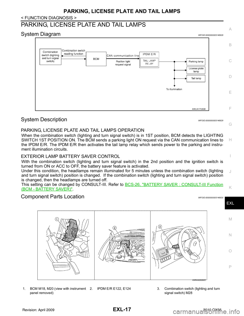
System DiagramINFOID:0000000005146628
System DescriptionINFOID:0000000005146629
PARKING, LICENSE PLATE AND TAIL LAMPS OPERATION
When the combination switch (lighting and turn signal s witch) is in 1ST position, BCM detects the LIGHTING
SWITCH 1ST POSITION ON. The BCM sends a parking light ON request via the CAN communication lines to
the IPDM E/R. The IPDM E/R then ac tivates the tail lamp relay which sends power to the parking and instru-
ment illumination circuits.
EXTERIOR LAMP BATTERY SAVER CONTROL
With the combination switch (lighting and turn signal switch) in the 2nd position and the ignition switch is
turned from ON or ACC to OFF, the battery saver feature is activated.
Under this condition, the headlamps remain illuminated fo r 5 minutes unless the combination switch (lighting
and turn signal switch) position is changed. If the combi nation switch (lighting and turn signal switch) position
is changed, then the headlamps are turned off.
This setting can be changed by CONSULT-III. Refer to BCS-26, "
BATTERY SAVER : CONSULT-III Function
(BCM - BATTERY SAVER)".
Component Parts LocationINFOID:0000000005146630
AWLIA1753GB
1. BCM M18, M20 (view with instrument
panel removed) 2. IPDM E/R E122, E124 3. Combination switch (lighting and turn
signal switch) M28
AWNIA0509ZZ
Revision: April 20092010 QX56
Page 2008 of 4210

EXL-32
< COMPONENT DIAGNOSIS >
HEADLAMP (HI) CIRCUIT
Is the fuse open?
YES >> Repair the harness and replace the fuse.
NO >> GO TO 2.
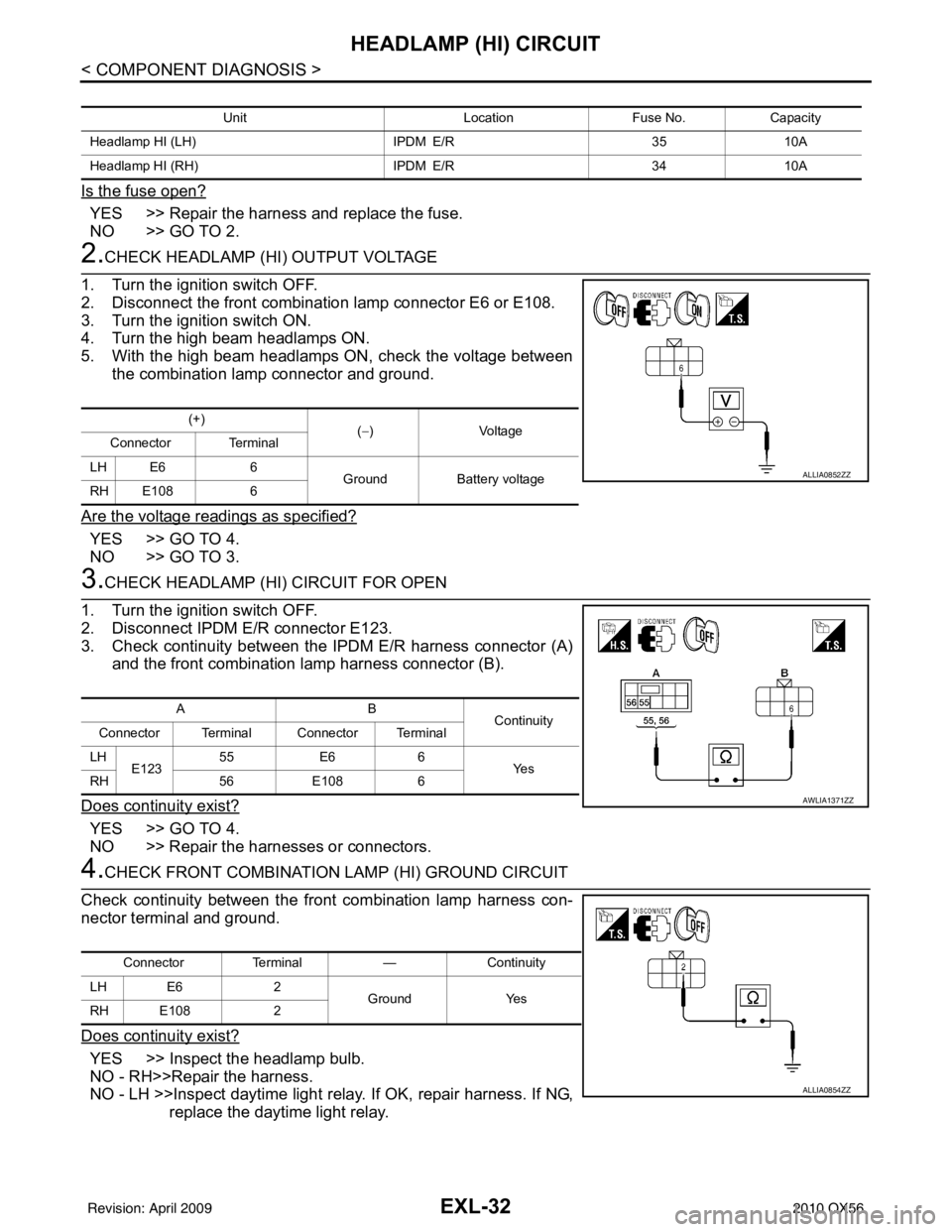
2.CHECK HEADLAMP (HI) OUTPUT VOLTAGE
1. Turn the ignition switch OFF.
2. Disconnect the front combination lamp connector E6 or E108.
3. Turn the ignition switch ON.
4. Turn the high beam headlamps ON.
5. With the high beam headlamps ON, check the voltage between the combination lamp connector and ground.
Are the voltage readings as specified?
YES >> GO TO 4.
NO >> GO TO 3.
3.CHECK HEADLAMP (HI) CIRCUIT FOR OPEN
1. Turn the ignition switch OFF.
2. Disconnect IPDM E/R connector E123.
3. Check continuity between the IPDM E/R harness connector (A) and the front combination lamp harness connector (B).
Does continuity exist?
YES >> GO TO 4.
NO >> Repair the harnesses or connectors.
4.CHECK FRONT COMBINATION LAMP (HI) GROUND CIRCUIT
Check continuity between the front combination lamp harness con-
nector terminal and ground.
Does continuity exist?
YES >> Inspect the headlamp bulb.
NO - RH>>Repair the harness.
NO - LH >>Inspect daytime light rela y. If OK, repair harness. If NG,
replace the daytime light relay.
Unit LocationFuse No.Capacity
Headlamp HI (LH) IPDM E/R3510A
Headlamp HI (RH) IPDM E/R3410A
(+)
(−)Voltage
Connector Terminal
LH E6 6 GroundBattery voltage
RH E108 6
ALLIA0852ZZ
AB
Continuity
Connector Terminal Connector Terminal
LH E123 55
E66
Ye s
RH 56E108 6
AWLIA1371ZZ
Connector Terminal —Continuity
LH E6 2
Ground Yes
RH E108 2
ALLIA0854ZZ
Revision: April 20092010 QX56
Page 2011 of 4210

HEADLAMP (LO) CIRCUITEXL-35
< COMPONENT DIAGNOSIS >
C
DE
F
G H
I
J
K
M A
B
EXL
N
O P
Is the fuse open?
YES >> Repair the harness and replace the fuse.
NO >> GO TO 2.
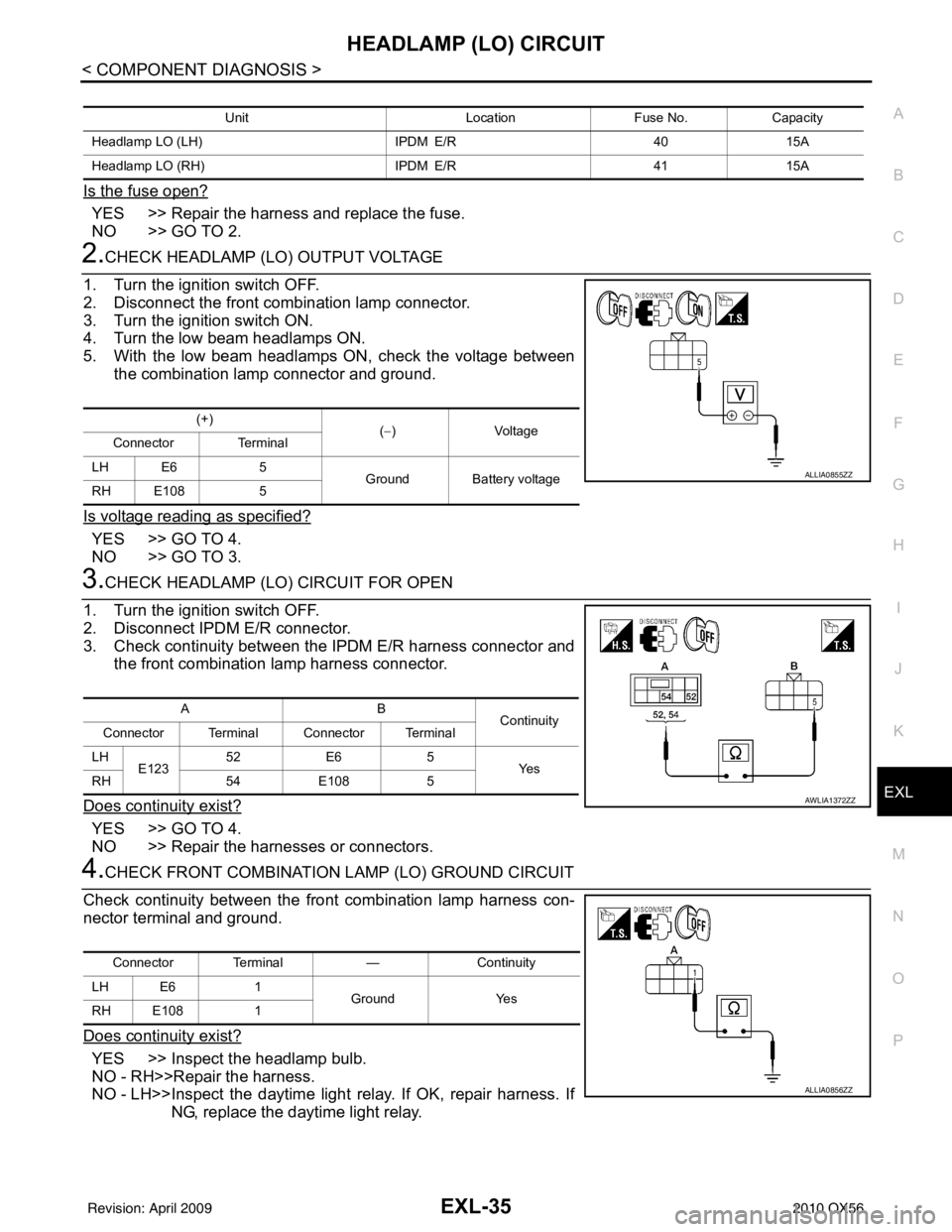
2.CHECK HEADLAMP (LO) OUTPUT VOLTAGE
1. Turn the ignition switch OFF.
2. Disconnect the front combination lamp connector.
3. Turn the ignition switch ON.
4. Turn the low beam headlamps ON.
5. With the low beam headlamps ON, check the voltage between the combination lamp connector and ground.
Is voltage reading as specified?
YES >> GO TO 4.
NO >> GO TO 3.
3.CHECK HEADLAMP (LO) CIRCUIT FOR OPEN
1. Turn the ignition switch OFF.
2. Disconnect IPDM E/R connector.
3. Check continuity between the IPDM E/R harness connector and the front combination lamp harness connector.
Does continuity exist?
YES >> GO TO 4.
NO >> Repair the harnesses or connectors.
4.CHECK FRONT COMBINATION LAMP (LO) GROUND CIRCUIT
Check continuity between the front combination lamp harness con-
nector terminal and ground.
Does continuity exist?
YES >> Inspect the headlamp bulb.
NO - RH>>Repair the harness.
NO - LH>>Inspect the daytime light relay. If OK, repair harness. If
NG, replace the daytime light relay.
Unit LocationFuse No.Capacity
Headlamp LO (LH) IPDM E/R4015A
Headlamp LO (RH) IPDM E/R4115A
(+)
(−)Voltage
Connector Terminal
LH E6 5
Ground Battery voltage
RH E108 5
ALLIA0855ZZ
AB
Continuity
Connector Terminal Connector Terminal
LH E123 52
E6 5
Ye s
RH 54E108 5
AWLIA1372ZZ
Connector Terminal —Continuity
LH E6 1
Ground Yes
RH E108 1
ALLIA0856ZZ
Revision: April 20092010 QX56
Page 2012 of 4210

EXL-36
< COMPONENT DIAGNOSIS >
FRONT FOG LAMP CIRCUIT
FRONT FOG LAMP CIRCUIT
DescriptionINFOID:0000000005146647
The IPDM E/R (intelligent power distribution module engine room) controls the front fog lamp relay based on
inputs from the BCM via the CAN communication lines. When the front fog lamp relay is energized, power
flows from the front fog lamp relay in the IPDM E/R to the front fog lamps.
Component Function CheckINFOID:0000000005146648
1.CHECK FRONT FOG LAMP OPERATION
WITHOUT CONSULT-III
1. Activate IPDM E/R auto active test. Refer to PCS-12, "
Diagnosis Description".
2. Check that the front fog lamp is turned ON.
CONSULT-III
1. Select "EXTERNAL LAMPS" of IPDM E/R active test item.
2. With operating the test items, Check that the front fog lamp is turned ON.
Is the front fog lamp turned ON?
YES >> Front fog lamp circuit is normal.
NO >> Refer to EXL-36, "
Diagnosis Procedure".
Diagnosis ProcedureINFOID:0000000005146649
Regarding Wiring Diagram information, refer to EXL-73, "Wiring Diagram".
1.CHECK FRONT FOG LAMP FUSE
1. Turn the ignition switch OFF.
2. Check that the following fuses are not open.
Is the fuse open?
YES >> Repair the harness and replace the fuse.
NO >> GO TO 2.
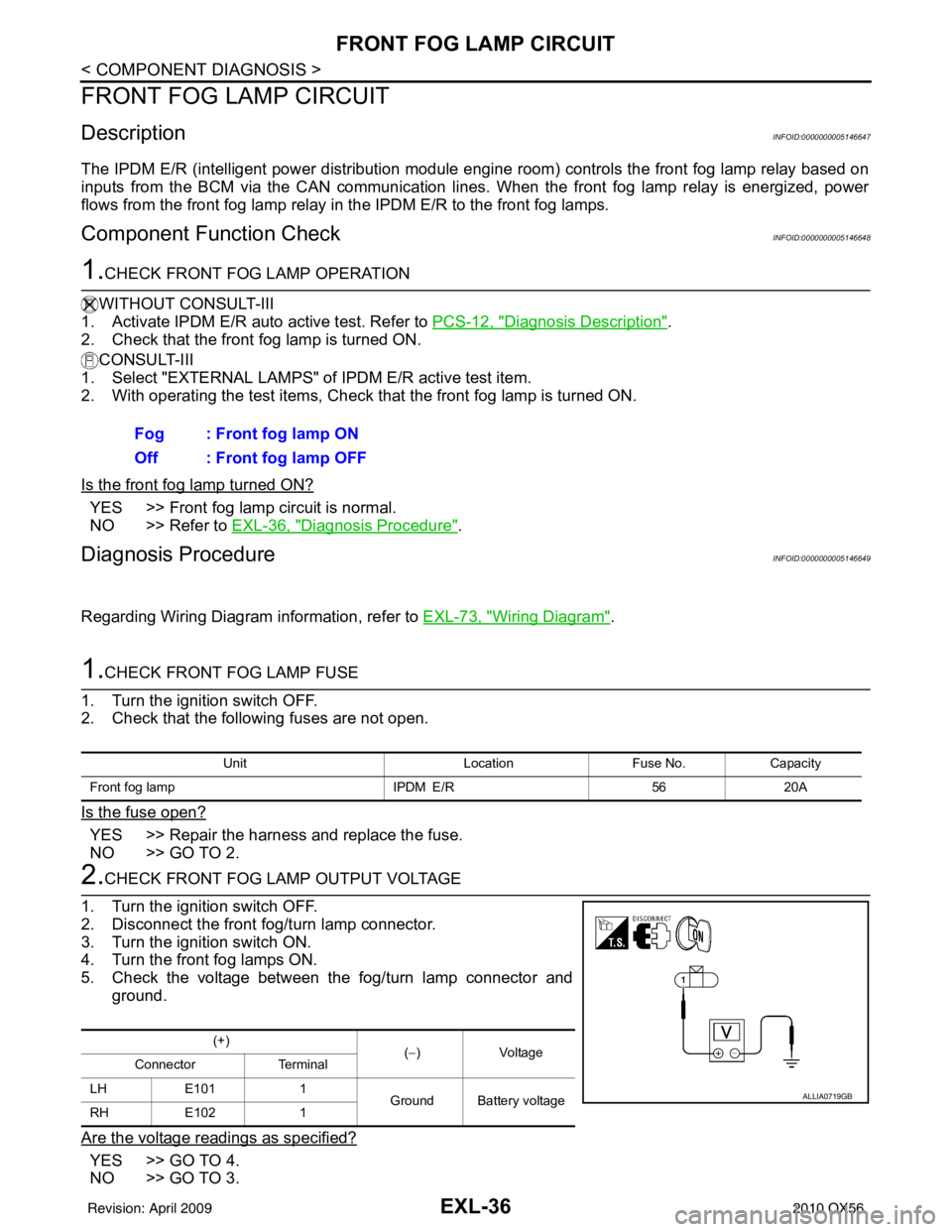
2.CHECK FRONT FOG LAMP OUTPUT VOLTAGE
1. Turn the ignition switch OFF.
2. Disconnect the front fog/turn lamp connector.
3. Turn the ignition switch ON.
4. Turn the front fog lamps ON.
5. Check the voltage between the fog/turn lamp connector and ground.
Are the voltage readings as specified?
YES >> GO TO 4.
NO >> GO TO 3. Fog : Front fog lamp ON
Off : Front fog lamp OFF
Unit
LocationFuse No.Capacity
Front fog lamp IPDM E/R5620A
(+)
(−)V olt a g e
Connector Terminal
LH E101 1
Ground Battery voltage
RH E102 1
ALLIA0719GB
Revision: April 20092010 QX56