2010 INFINITI QX56 battery location
[x] Cancel search: battery locationPage 2778 of 4210
MWI-16
< FUNCTION DIAGNOSIS >
METER SYSTEM
VOLTAGE GAUGE : Component Description
INFOID:0000000005146053
ODO/TRIP METER
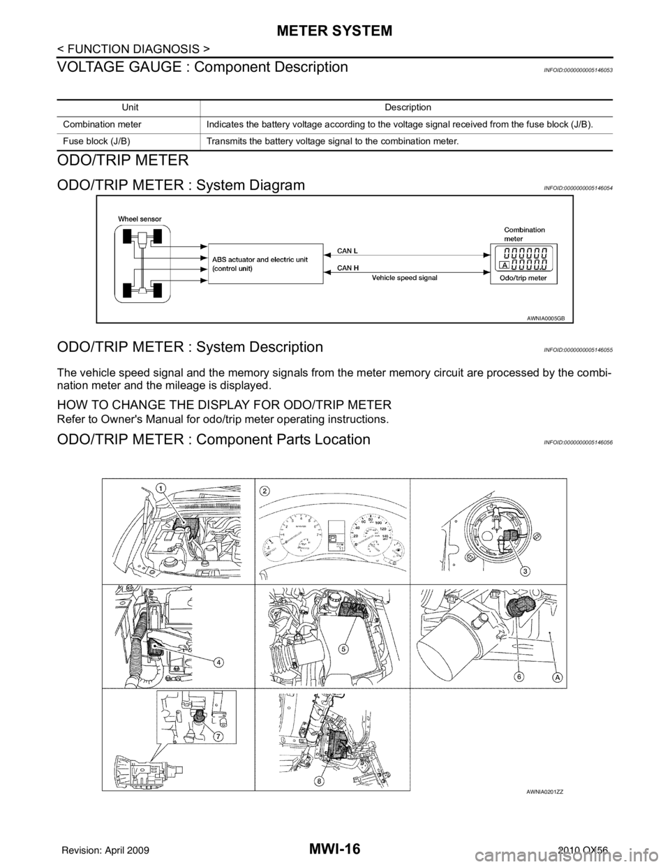
ODO/TRIP METER : System DiagramINFOID:0000000005146054
ODO/TRIP METER : System DescriptionINFOID:0000000005146055
The vehicle speed signal and the memory signals from the meter memory circuit are processed by the combi-
nation meter and the mileage is displayed.
HOW TO CHANGE THE DISPLAY FOR ODO/TRIP METER
Refer to Owner's Manual for odo/tr ip meter operating instructions.
ODO/TRIP METER : Component Parts LocationINFOID:0000000005146056
Unit Description
Combination meter Indicates the battery voltage according to the voltage signal received from the fuse block (J/B).
Fuse block (J/B) Transmits the battery voltage signal to the combination meter.
AWNIA0005GB
AWNIA0201ZZ
Revision: April 20092010 QX56
Page 2780 of 4210
MWI-18
< FUNCTION DIAGNOSIS >
METER SYSTEM
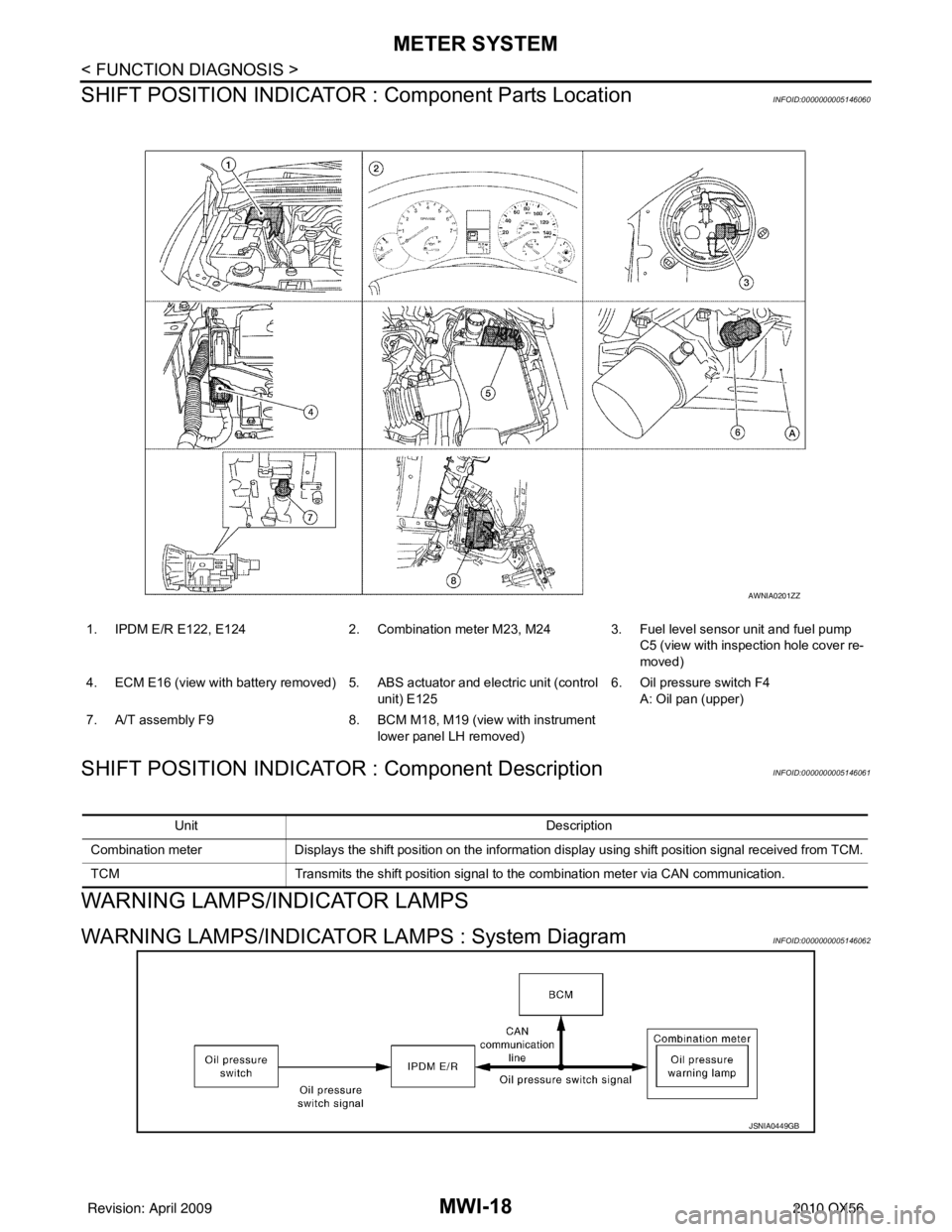
SHIFT POSITION INDICATOR : Component Parts Location
INFOID:0000000005146060
SHIFT POSITION INDICATOR : Component DescriptionINFOID:0000000005146061
WARNING LAMPS/INDICATOR LAMPS
WARNING LAMPS/INDICATOR LAMPS : System DiagramINFOID:0000000005146062
1. IPDM E/R E122, E124 2. Combination meter M23, M24 3. Fuel level sensor unit and fuel pump
C5 (view with inspection hole cover re-
moved)
4. ECM E16 (view with battery removed) 5. ABS actuator and electric unit (control
unit) E125 6. Oil pressure switch F4
A: Oil pan (upper)
7. A/T assembly F9 8. BCM M18, M19 (view with instrument
lower panel LH removed)
AWNIA0201ZZ
Unit Description
Combination meter Displays the shift position on the information display using shift position signal received from TCM.
TCM Transmits the shift position signal to the combination meter via CAN communication.
JSNIA0449GB
Revision: April 20092010 QX56
Page 2781 of 4210
MWI
METER SYSTEMMWI-19
< FUNCTION DIAGNOSIS >
C
DE
F
G H
I
J
K L
M B A
O P
WARNING LAMPS/INDICATOR LAMPS : System DescriptionINFOID:0000000005146063
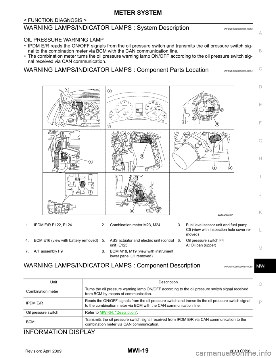
OIL PRESSURE WARNING LAMP
• IPDM E/R reads the ON/OFF signals from the oil pressure switch and transmits the oil pressure switch sig-
nal to the combination meter via BCM with the CAN communication line.
• The combination meter turns the oil pressure warning lamp ON/OFF according to the oil pressure switch sig- nal received via CAN communication.
WARNING LAMPS/INDICATOR LAMPS : Component Parts LocationINFOID:0000000005146064
WARNING LAMPS/INDICATOR LAMPS : Component DescriptionINFOID:0000000005146065
INFORMATION DISPLAY
1. IPDM E/R E122, E124 2. Combination meter M23, M24 3. Fuel level sensor unit and fuel pump
C5 (view with inspection hole cover re-
moved)
4. ECM E16 (view with battery removed) 5. ABS actuator and electric unit (control unit) E1256. Oil pressure switch F4
A: Oil pan (upper)
7. A/T assembly F9 8. BCM M18, M19 (view with instrument
lower panel LH removed)
AWNIA0201ZZ
Unit Description
Combination meter Turns the oil pressure warning lamp ON/OFF according to the oil pressure switch signal received
from BCM by means of communication.
IPDM E/R Reads the ON/OFF signals from the oil pressure switch and transmits the oil pressure switch signal
to the combination meter via BCM with the CAN communication line.
Oil pressure switch Refer to MWI-34, "
Description".
BCM Transmits the oil pressure switch signal received from IPDM E/R via CAN communication to the
combination meter via CAN communication.
Revision: April 20092010 QX56
Page 2783 of 4210
MWI
METER SYSTEMMWI-21
< FUNCTION DIAGNOSIS >
C
DE
F
G H
I
J
K L
M B A
O P
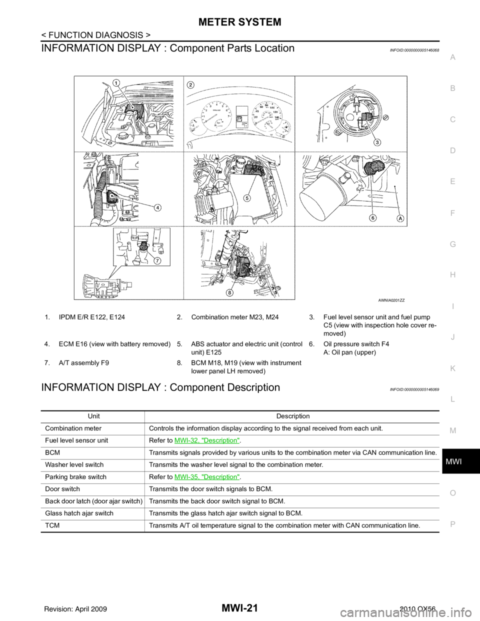
INFORMATION DISPLAY : Co mponent Parts LocationINFOID:0000000005146068
INFORMATION DISPLAY : Component DescriptionINFOID:0000000005146069
1. IPDM E/R E122, E124 2. Combination meter M23, M24 3. Fuel level sensor unit and fuel pump
C5 (view with inspection hole cover re-
moved)
4. ECM E16 (view with battery removed) 5. ABS actuator and electric unit (control unit) E1256. Oil pressure switch F4
A: Oil pan (upper)
7. A/T assembly F9 8. BCM M18, M19 (view with instrument
lower panel LH removed)
AWNIA0201ZZ
Unit Description
Combination meter Controls the information display according to the signal received from each unit.
Fuel level sensor unit Refer to MWI-32, "
Description".
BCM Transmits signals provided by various units to the combination meter via CAN communication line.
Washer level switch Transmits the washer level signal to the combination meter.
Parking brake switch Refer to MWI-35, "
Description".
Door switch Transmits the door switch signals to BCM.
Back door latch (door ajar switch) Transmits the back door switch signal to BCM.
Glass hatch ajar switch Transmits the glass hatch ajar switch signal to BCM.
TCM Transmits A/T oil temperature signal to the combination meter with CAN communication line.
Revision: April 20092010 QX56
Page 2876 of 4210
PCS
PCS-1
ELECTRICAL & POWER CONTROL
C
DE
F
G H
I
J
K L
B
SECTION PCS
A
O P
N
CONTENTS
POWER CONTROL SYSTEM
IPDM E/R
BASIC INSPECTION ....... .............................
2
DIAGNOSIS AND REPAIR WORKFLOW ..... .....2
Work Flow ........................................................... ......2
FUNCTION DIAGNOSIS ...............................5
RELAY CONTROL SYSTEM ......................... .....5
System Diagram .................................................. ......5
System Description ...................................................6
Component Parts Location ........................................7
POWER CONTROL SYSTEM .............................8
System Diagram .................................................. ......8
System Description ...................................................8
SIGNAL BUFFER SYSTEM ................................9
System Diagram .................................................. ......9
System Description ...................................................9
POWER CONSUMPTION CONTROL SYS-
TEM ....................................................................
10
System Diagram .................................................. ....10
System Description .................................................10
Component Parts Location ......................................11
DIAGNOSIS SYSTEM (IPDM E/R) .....................12
Diagnosis Description ......................................... ....12
CONSULT - III Function (IPDM E/R) .......................14
COMPONENT DIAGNOSIS .........................17
U1000 CAN COMM CIRCUIT ...........................17
Description ........................................................... ....17
DTC Logic ................................................................17
Diagnosis Procedure ...............................................17
POWER SUPPLY AND GROUND CIRCUIT ....18
Diagnosis Procedure ...............................................18
ECU DIAGNOSIS .........................................19
IPDM E/R (INTELLIGENT POWER DISTRI-
BUTION MODULE ENGINE ROOM) ................
19
Reference Value .................................................. ....19
Terminal Layout .......................................................21
Physical Values ................................................... ....22
Wiring Diagram ........................................................27
Fail Safe ..................................................................30
DTC Index ...............................................................32
PRECAUTION ..............................................33
PRECAUTIONS .................................................33
Precaution for Supplemental Restraint System
(SRS) "AIR BAG" and "SEAT BELT PRE-TEN-
SIONER" ............................................................. ....
33
Precaution Necessary for Steering Wheel Rota-
tion After Battery Disconnect ...................................
33
REMOVAL AND INSTALLATION ...............35
IPDM E/R (INTELLIGENT POWER DISTRI-
BUTION MODULE ENGINE ROOM) ................
35
Removal and Installation of IPDM E/R ................ ....35
Revision: April 20092010 QX56
Page 2911 of 4210

PG
PG-1
ELECTRICAL & POWER CONTROL
C
DE
F
G H
I
J
K L
B
SECTION PG
A
O P
N
CONTENTS
POWER SUPPLY, GROUND & CIRCUIT ELEMENTS
PRECAUTION .......
........................................2
PRECAUTIONS .............................................. .....2
Precaution for Supplemental Restraint System
(SRS) "AIR BAG" and "SEAT BELT PRE-TEN-
SIONER" ............................................................. ......
2
Precaution Necessary for Steering Wheel Rota-
tion After Battery Disconnect ............................... ......
2
Precaution for Power Generation Variable Voltage
Control System ..........................................................
3
PREPARATION ............................................4
PREPARATION .............................................. .....4
Special Service Tool ........................................... ......4
Commercial Service Tool ..........................................4
BASIC INSPECTION ....................................5
BATTERY ....................................................... .....5
How to Handle Battery ........................................ ......5
Work Flow ........................................................... ......7
INSPECTION AND ADJUSTMENT .....................8
ADDITIONAL SERVICE WHEN REMOVING BAT-
TERY NEGATIVE TERMINAL ............................... ......
8
ADDITIONAL SERVICE WHEN REMOVING
BATTERY NEGATIVE TERMINAL : Special Re-
pair Requirement ................................................. ......
8
COMPONENT DIAGNOSIS ..........................9
POWER SUPPLY ROUTING CIRCUIT .......... .....9
Wiring Diagram — Battery Power Supply — ....... ......9
Wiring Diagram — Accessory Power Supply — .....18
Wiring Diagram — Ignition Power Supply — ..........22
Fuse ........................................................................30
Fusible Link .............................................................30
GROUND ...........................................................31
Ground Distribution .............................................. ....31
HARNESS .........................................................41
Harness Layout ................................................... ....41
ELECTRICAL UNITS LOCATION ....................61
Electrical Units Location ..........................................61
HARNESS CONNECTOR .................................64
Description ...............................................................64
STANDARDIZED RELAY .................................67
Description ...............................................................67
FUSE BLOCK - JUNCTION BOX (J/B) ............69
Terminal Arrangement .............................................69
FUSE, FUSIBLE LINK AND RELAY BOX ........70
Terminal Arrangement .............................................70
IPDM E/R (INTELLIGENT POWER DISTRI-
BUTION MODULE ENGINE ROOM) ................
72
IPDM E/R Terminal Arrangement - Type A .............72
IPDM E/R Terminal Arrangement - Type B .............73
ON-VEHICLE REPAIR .................................74
BATTERY ..........................................................74
Removal and Installation ..................................... ....74
SERVICE DATA AND SPECIFICATIONS
(SDS) ............... .......................................... ...
75
SERVICE DATA AND SPECIFICATIONS
(SDS) .................................................................
75
Battery ................................................................. ....75
Revision: April 20092010 QX56
Page 3115 of 4210
PRECAUTIONSRAX-3
< PRECAUTION >
CEF
G H
I
J
K L
M A
B
RAX
N
O P
5. When the repair work is completed, return the ignition switch to the ″LOCK ″ position before connecting
the battery cables. (At this time, the steering lock mechanism will engage.)
6. Perform a self-diagnosis check of al l control units using CONSULT-III.
PrecautionINFOID:0000000005148950
Observe the following precautions when disassembling and servicing drive shaft.
• Perform work in a location which is as dust-free as possible.
• Before disassembling and servicing, clean the outside of parts.
• Prevention of the entry of foreign objects must be tak en into account during disassembly of the service loca-
tion.
• Disassembled parts must be carefully reassembled in the correct order. If work is interrupted, a clean cover
must be placed over parts.
• Paper shop cloths must be used. Fabric shop cloths must not be used because of the danger of lint adhering to parts.
• Disassembled parts (except for rubber parts) should be cleaned with kerosene which shall be removed by blowing with air or wiping with paper shop cloths.
Revision: April 20092010 QX56
Page 3238 of 4210
SCS-6
< FUNCTION DIAGNOSIS >
SUSPENSION CONTROL SYSTEM
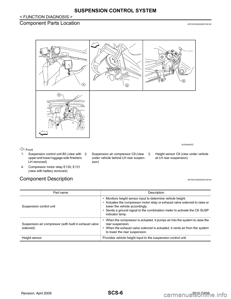
Component Parts Location
INFOID:0000000005148148
:Front
Component DescriptionINFOID:0000000005148149
1. Suspension control unit B3 (view with upper and lower luggage side finishers
LH removed) 2. Suspension air compressor C9 (view
under vehicle behind LH rear suspen-
sion) 3. Height sensor C8 (view under vehicle
at LH rear suspension)
4. Compressor motor relay E130, E131 (view with battery removed)
ALEIA0044ZZ
Part name Description
Suspension control unit • Monitors height sensor input to determine vehicle height.
• Actuates the compressor motor relay or exhaust valve solenoid to raise or
lower the vehicle accordingly.
• Sends a ground signal to the combination meter to activate the CK SUSP indicator lamp.
Suspension air compressor (with built in exhaust valve
solenoid) • When the compressor is actuated, it pumps air into the system to raise the
rear suspension.
• When the exhaust valve solenoid is actuated, it vents air from the system to lower the rear suspension.
Height sensor Provides vehicle height input to the suspension control unit.
Revision: April 20092010 QX56