Page 2478 of 4210
ILLUMINATION CONTROL SYSTEMINL-9
< FUNCTION DIAGNOSIS >
C
DE
F
G H
I
J
K
M A
B
INL
N
O P
ILLUMINATION CONTROL SYSTEM
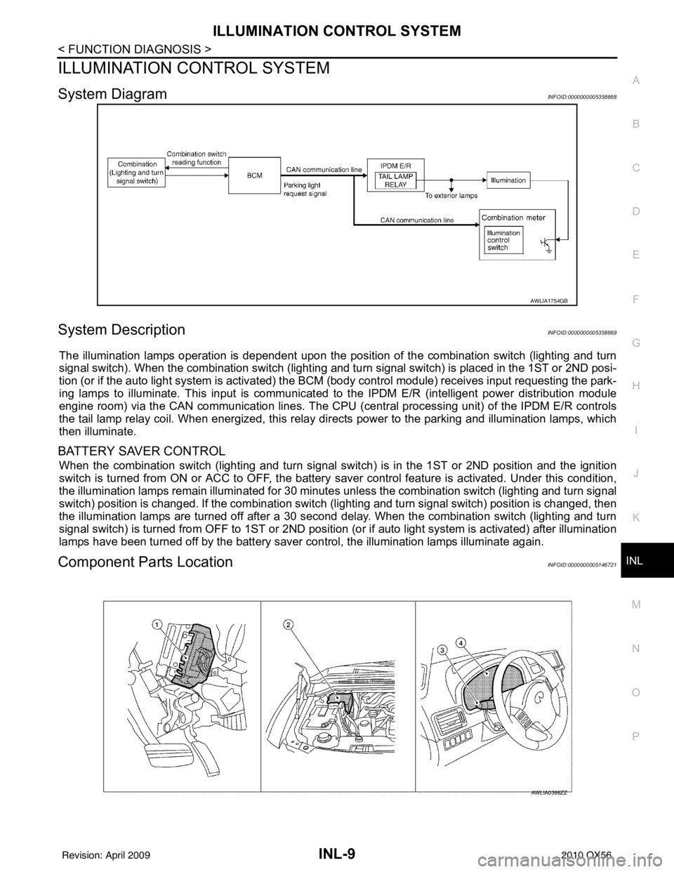
System DiagramINFOID:0000000005358668
System DescriptionINFOID:0000000005358669
The illumination lamps operation is dependent upon the posit ion of the combination switch (lighting and turn
signal switch). When the combination switch (lighting and turn signal switch) is placed in the 1ST or 2ND posi-
tion (or if the auto light system is activated) the BCM (body control modul e) receives input requesting the park-
ing lamps to illuminate. This input is communicated to the IPDM E/R (intelligent power distribution module
engine room) via the CAN communication lines. The CPU (central processing unit) of the IPDM E/R controls
the tail lamp relay coil. When energized, this relay directs power to the parking and illumination lamps, which
then illuminate.
BATTERY SAVER CONTROL
When the combination switch (lighting and turn signal s witch) is in the 1ST or 2ND position and the ignition
switch is turned from ON or ACC to OFF, the battery saver control feature is activated. Under this condition,
the illumination lamps remain illuminated for 30 minutes unless the combination switch (lighting and turn signal
switch) position is changed. If the combination switch (lighting and turn signal switch) position is changed, then
the illumination lamps are turned off after a 30 second delay. When the combination switch (lighting and turn
signal switch) is turned from OFF to 1ST or 2ND position (or if auto light system is activated) after illumination
lamps have been turned off by the battery saver c ontrol, the illumination lamps illuminate again.
Component Parts LocationINFOID:0000000005146721
AWLIA1754GB
AWLIA0398ZZ
Revision: April 20092010 QX56
Page 2689 of 4210

PRECAUTIONSLU-3
< PRECAUTION >
C
DE
F
G H
I
J
K L
M A
LU
NP
O
5. When the repair work is completed, return the ignition switch to the
″LOCK ″ position before connecting
the battery cables. (At this time, the steering lock mechanism will engage.)
6. Perform a self-diagnosis check of al l control units using CONSULT-III.
Precaution for Liquid GasketINFOID:0000000005149020
REMOVAL OF LIQUID GASKET SEALING
• After removing the bolts and nuts, separate the mating surface and
remove the old liquid gasket sealing using Tool.
CAUTION:
Do not damage the mating surfaces.
• Tap the seal cutter to insert it (1).
• In areas where the Tool is difficult to use, lightly tap to slide it (2).
LIQUID GASKET APPLICATION PROCEDURE
1. Remove the old liquid gasket adhering to the gasket application surface and the mating surface using suitable tool.
• Remove the liquid gasket completely from the groove of the
liquid gasket application surface, bolts, and bolt holes.
2. Thoroughly clean the mating surfaces and remove adhering moisture, grease and foreign material.
3. Attach the liquid gasket tube to the Tool. Use Genuine RTV Silicone Sealant or equivalent. Refer to
GI-15, "
Recommended Chemical Products and Sealants".
4. Apply the liquid gasket without breaks to the specified location.
• If there is a groove for the liquid gasket application, apply theliquid gasket to the groove.
• As for the bolt holes, normally apply the liquid gasket inside
the holes. If specified in the procedure, it should also be
applied outside the holes.
• Within five minutes of liquid gasket application, install the mat-
ing component.
• If the liquid gasket protrudes, wipe it off immediately.
• Do not retighten after the installation.
• Wait 30 minutes or more after installation before refilling the engine with engine oil and engine coolant.
CAUTION:
If there are specific instructions in this manual, observe them.
Tool number : KV10111100 (J-37228)
WBIA0566E
PBIC0003E
Tool number : WS39930000 ( — )
WBIA0567E
SEM159F
Revision: April 20092010 QX56
Page 2769 of 4210
MWI
METER SYSTEMMWI-7
< FUNCTION DIAGNOSIS >
C
DE
F
G H
I
J
K L
M B A
O P
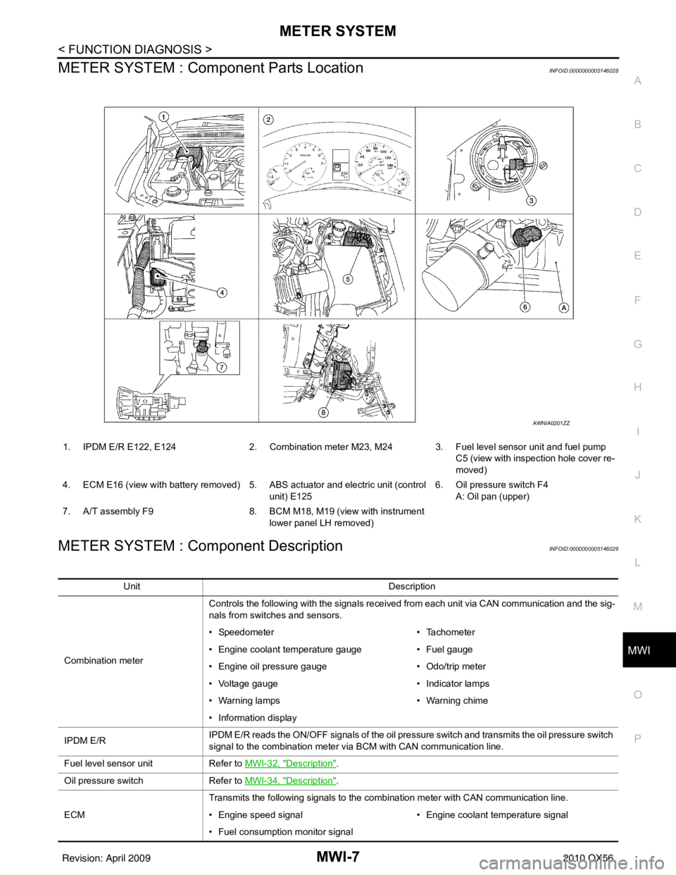
METER SYSTEM : Com ponent Parts LocationINFOID:0000000005146028
METER SYSTEM : Component DescriptionINFOID:0000000005146029
1. IPDM E/R E122, E124 2. Combination meter M23, M24 3. Fuel level sensor unit and fuel pump
C5 (view with inspection hole cover re-
moved)
4. ECM E16 (view with battery removed) 5. ABS actuator and electric unit (control unit) E1256. Oil pressure switch F4
A: Oil pan (upper)
7. A/T assembly F9 8. BCM M18, M19 (view with instrument
lower panel LH removed)
AWNIA0201ZZ
Unit Description
Combination meter Controls the following with the signals received from each unit via CAN communication and the sig-
nals from switches and sensors.
• Speedometer
• Tachometer
• Engine coolant temperature gauge • Fuel gauge
• Engine oil pressure gauge • Odo/trip meter
• Voltage gauge • Indicator lamps
• Warning lamps • Warning chime
• Information display
IPDM E/R IPDM E/R reads the ON/OFF signals of the oil pressure switch and transmits the oil pressure switch
signal to the combination meter via BCM with CAN communication line.
Fuel level sensor unit Refer to MWI-32, "
Description".
Oil pressure switch Refer to MWI-34, "
Description".
ECM Transmits the following signals to the combination meter with CAN communication line.
• Engine speed signal
• Engine coolant temperature signal
• Fuel consumption monitor signal
Revision: April 20092010 QX56
Page 2771 of 4210
MWI
METER SYSTEMMWI-9
< FUNCTION DIAGNOSIS >
C
DE
F
G H
I
J
K L
M B A
O P
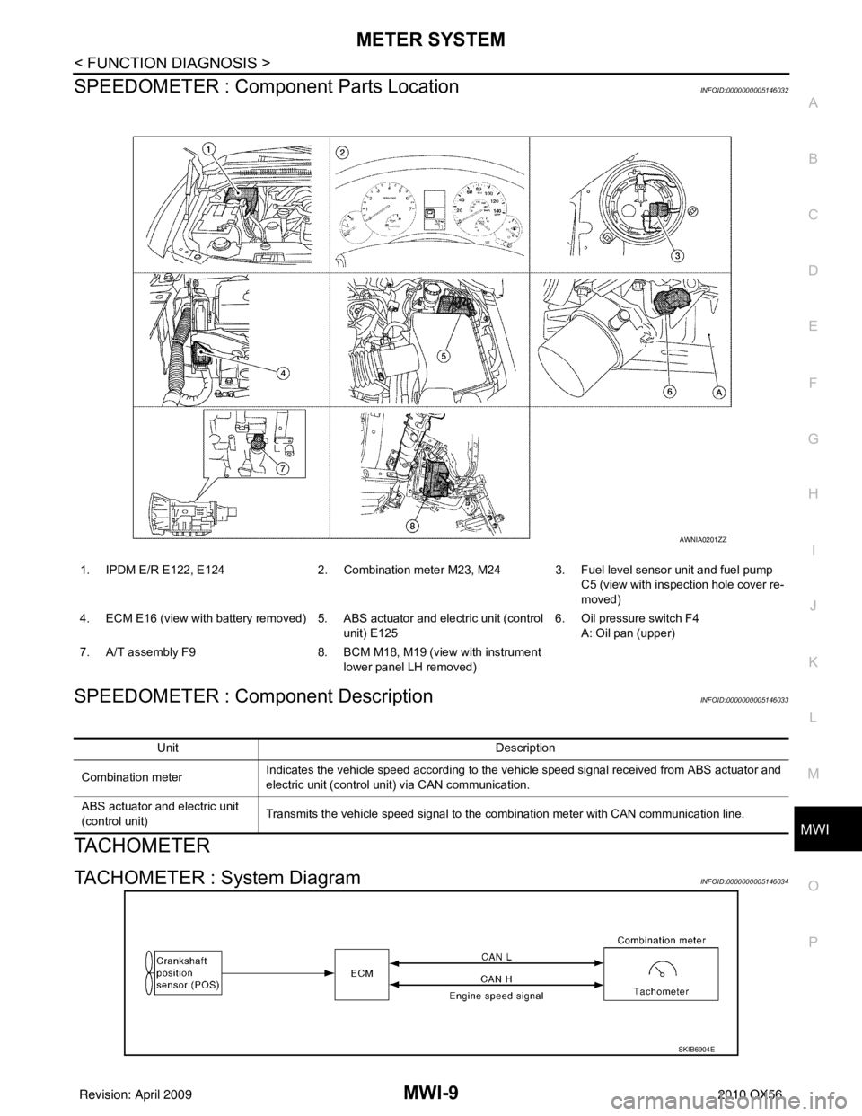
SPEEDOMETER : Compone nt Parts LocationINFOID:0000000005146032
SPEEDOMETER : Component DescriptionINFOID:0000000005146033
TACHOMETER
TACHOMETER : System DiagramINFOID:0000000005146034
1. IPDM E/R E122, E124 2. Combination meter M23, M24 3. Fuel level sensor unit and fuel pump
C5 (view with inspection hole cover re-
moved)
4. ECM E16 (view with battery removed) 5. ABS actuator and electric unit (control unit) E1256. Oil pressure switch F4
A: Oil pan (upper)
7. A/T assembly F9 8. BCM M18, M19 (view with instrument
lower panel LH removed)
AWNIA0201ZZ
Unit Description
Combination meter Indicates the vehicle speed according to the vehicle speed signal received from ABS actuator and
electric unit (control unit) via CAN communication.
ABS actuator and electric unit
(control unit) Transmits the vehicle speed signal to the combination meter with CAN communication line.
SKIB6904E
Revision: April 20092010 QX56
Page 2772 of 4210
MWI-10
< FUNCTION DIAGNOSIS >
METER SYSTEM
TACHOMETER : System Description
INFOID:0000000005146035
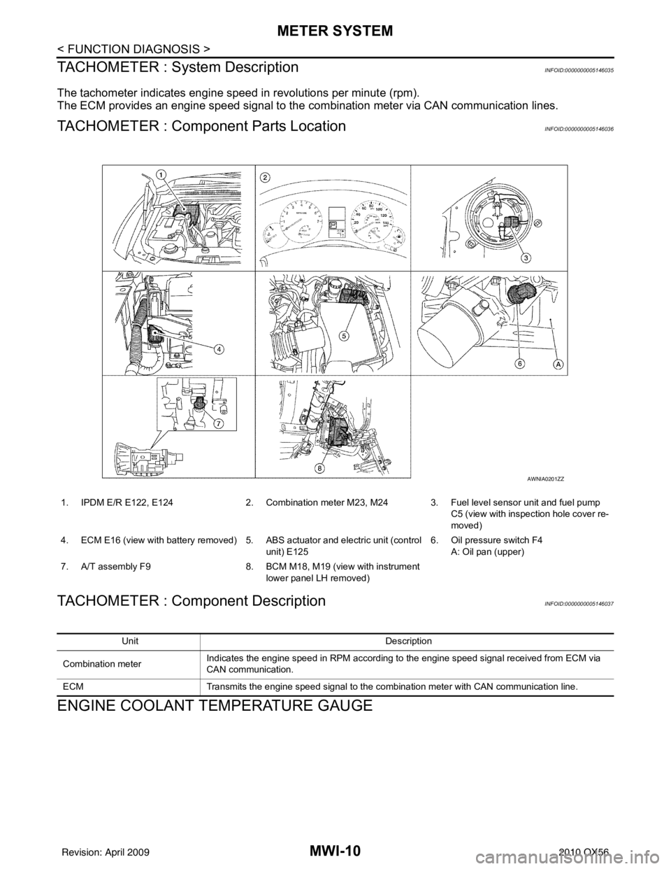
The tachometer indicates engine speed in revolutions per minute (rpm).
The ECM provides an engine speed signal to the co mbination meter via CAN communication lines.
TACHOMETER : Component Parts LocationINFOID:0000000005146036
TACHOMETER : Component DescriptionINFOID:0000000005146037
ENGINE COOLANT TEMPERATURE GAUGE
1. IPDM E/R E122, E1242. Combination meter M23, M24 3. Fuel level sensor unit and fuel pump
C5 (view with inspection hole cover re-
moved)
4. ECM E16 (view with battery removed) 5. ABS actuator and electric unit (control
unit) E125 6. Oil pressure switch F4
A: Oil pan (upper)
7. A/T assembly F9 8. BCM M18, M19 (view with instrument
lower panel LH removed)
AWNIA0201ZZ
Unit Description
Combination meter Indicates the engine speed in RPM according to the engine speed signal received from ECM via
CAN communication.
ECM Transmits the engine speed signal to the combination meter with CAN communication line.
Revision: April 20092010 QX56
Page 2773 of 4210
MWI
METER SYSTEMMWI-11
< FUNCTION DIAGNOSIS >
C
DE
F
G H
I
J
K L
M B A
O P
ENGINE COOLANT TEMPERATURE GAUGE : System DiagramINFOID:0000000005146038
ENGINE COOLANT TEMPERATURE GAUGE : System DescriptionINFOID:0000000005146039
The engine coolant temperature gauge indicates the engine coolant temperature.
The ECM provides an engine coolant temperature signal to the combination meter via CAN communication
lines.
ENGINE COOLANT TEMPERATURE GA UGE : Component Parts Location
INFOID:0000000005146040
SKIB6905E
1. IPDM E/R E122, E124 2. Combination meter M23, M24 3. Fuel level sensor unit and fuel pump
C5 (view with inspection hole cover re-
moved)
4. ECM E16 (view with battery removed) 5. ABS actuator and electric unit (control unit) E1256. Oil pressure switch F4
A: Oil pan (upper)
7. A/T assembly F9 8. BCM M18, M19 (view with instrument
lower panel LH removed)
AWNIA0201ZZ
Revision: April 20092010 QX56
Page 2776 of 4210
MWI-14
< FUNCTION DIAGNOSIS >
METER SYSTEM
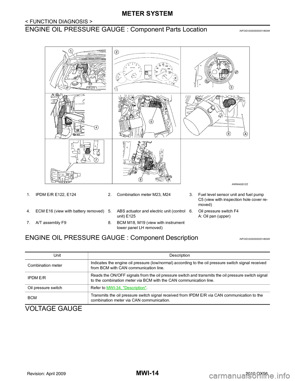
ENGINE OIL PRESSURE GAUGE : Component Parts Location
INFOID:0000000005146048
ENGINE OIL PRESSURE GAUGE : Component DescriptionINFOID:0000000005146049
VOLTAGE GAUGE
1. IPDM E/R E122, E124 2. Combination meter M23, M24 3. Fuel level sensor unit and fuel pump
C5 (view with inspection hole cover re-
moved)
4. ECM E16 (view with battery removed) 5. ABS actuator and electric unit (control
unit) E125 6. Oil pressure switch F4
A: Oil pan (upper)
7. A/T assembly F9 8. BCM M18, M19 (view with instrument
lower panel LH removed)
AWNIA0201ZZ
Unit Description
Combination meter Indicates the engine oil pressure (low/normal) according to the oil pressure switch signal received
from BCM with CAN
communication line.
IPDM E/R Reads the ON/OFF signals from the oil pressure switch and transmits the oil pressure switch signal
to the combination meter via BCM with the CAN communication line.
Oil pressure switch Refer to MWI-34, "
Description".
BCM Transmits the oil pressure switch signal received from IPDM E/R via CAN communication to the
combination meter via CAN communication.
Revision: April 20092010 QX56
Page 2777 of 4210
MWI
METER SYSTEMMWI-15
< FUNCTION DIAGNOSIS >
C
DE
F
G H
I
J
K L
M B A
O P
VOLTAGE GAUGE : System DiagramINFOID:0000000005146050
VOLTAGE GAUGE : System DescriptionINFOID:0000000005146051
The voltage gauge indicates the battery/charging system voltage.
The voltage gauge is regulated by the unified meter control unit.
VOLTAGE GAUGE : Component Parts LocationINFOID:0000000005146052
AWNIA0106GB
1. IPDM E/R E122, E124 2. Combination meter M23, M24 3. Fuel level sensor unit and fuel pump
C5 (view with inspection hole cover re-
moved)
4. ECM E16 (view with battery removed) 5. ABS actuator and electric unit (control unit) E1256. Oil pressure switch F4
A: Oil pan (upper)
7. A/T assembly F9 8. BCM M18, M19 (view with instrument
lower panel LH removed)
AWNIA0201ZZ
Revision: April 20092010 QX56