2010 BMW MOTORRAD G 650 GS Rider's Manual (in English)
-
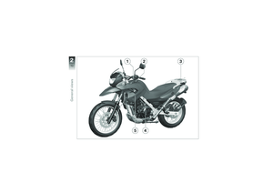
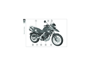
 1
1 -
 2
2 -
 3
3 -
 4
4 -
 5
5 -
 6
6 -
 7
7 -
 8
8 -
 9
9 -
 10
10 -
 11
11 -
 12
12 -
 13
13 -
 14
14 -
 15
15 -
 16
16 -
 17
17 -
 18
18 -
 19
19 -
 20
20 -
 21
21 -
 22
22 -
 23
23 -
 24
24 -
 25
25 -
 26
26 -
 27
27 -
 28
28 -
 29
29 -
 30
30 -
 31
31 -
 32
32 -
 33
33 -
 34
34 -
 35
35 -
 36
36 -
 37
37 -
 38
38 -
 39
39 -
 40
40 -
 41
41 -
 42
42 -
 43
43 -
 44
44 -
 45
45 -
 46
46 -
 47
47 -
 48
48 -
 49
49 -
 50
50 -
 51
51 -
 52
52 -
 53
53 -
 54
54 -
 55
55 -
 56
56 -
 57
57 -
 58
58 -
 59
59 -
 60
60 -
 61
61 -
 62
62 -
 63
63 -
 64
64 -
 65
65 -
 66
66 -
 67
67 -
 68
68 -
 69
69 -
 70
70 -
 71
71 -
 72
72 -
 73
73 -
 74
74 -
 75
75 -
 76
76 -
 77
77 -
 78
78 -
 79
79 -
 80
80 -
 81
81 -
 82
82 -
 83
83 -
 84
84 -
 85
85 -
 86
86 -
 87
87 -
 88
88 -
 89
89 -
 90
90 -
 91
91 -
 92
92 -
 93
93 -
 94
94 -
 95
95 -
 96
96 -
 97
97 -
 98
98 -
 99
99 -
 100
100 -
 101
101 -
 102
102 -
 103
103 -
 104
104 -
 105
105 -
 106
106 -
 107
107 -
 108
108 -
 109
109 -
 110
110 -
 111
111 -
 112
112 -
 113
113 -
 114
114 -
 115
115 -
 116
116 -
 117
117 -
 118
118 -
 119
119 -
 120
120 -
 121
121 -
 122
122 -
 123
123 -
 124
124 -
 125
125 -
 126
126 -
 127
127 -
 128
128 -
 129
129 -
 130
130 -
 131
131 -
 132
132 -
 133
133 -
 134
134 -
 135
135

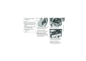
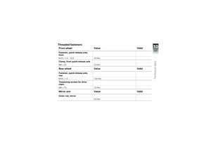
Fastener, quick-releaseaxle, front
45 Nm
Remove the front-wheel stand.
Apply the front brake and firmlycompress the front forks sever-al times
Tighten axle clamping screw2to the specified torque.
Cla")

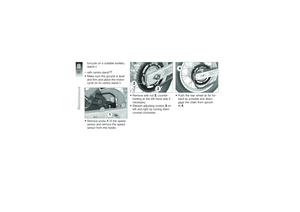
torcycle on a suitable auxiliarystand.
with centre standOE
Make sure the ground is leveland firm and place the motor-cycle on its centre stand.
Remove screw1of the speedsensor and remove the speedsen")

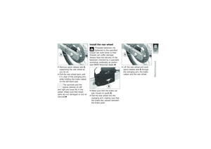
Remove quick-release axle5,supporting the rear wheel asyou do so.
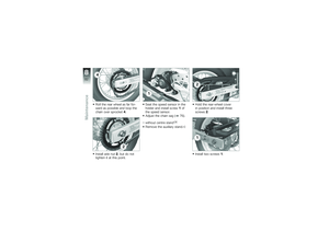
Roll the rear wheel back untilit is clear of the swinging arm,while holding the brake caliperon the left-hand side.
The sprocket and")

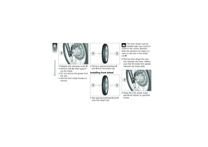
Roll the rear wheel as far for-ward as possible and loop thechain over sprocket4.
Install axle nut2, but do nottighten it at this point.
Seat the speed sensor in theholder and install screw1ofthe spe")

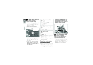
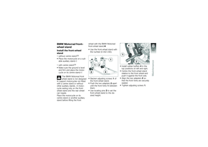
BMW Motorrad front-
wheel stand
Install the front-wheel
stand
without centre standOE
Place the motorcycle on a suit-able auxiliary stand.
with centre standOE
Make sure the ground is leveland firm and")

If the front of the motor-cycle is raised too far theauxiliary stand will lift clear of theground and the motorcycle couldtopple to one side.
When raising the motorcycle,make sure that the auxiliary")

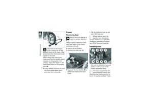
nical data\". The figures in thegraphic correspond to the fusenumbers.
Close the fuse cover.
The latch engages with anaudible click.
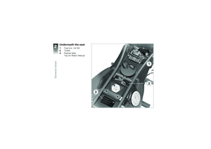
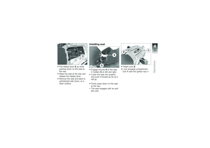
Installing seat (39).
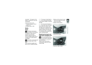
Bulbs
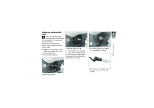
Notes
A defective bulb placesyour safet")

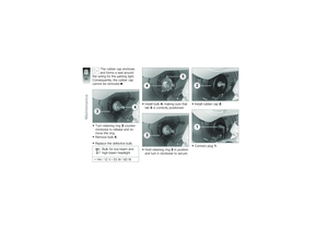
The rubber cap enclosesand forms a seal aroundthe wiring for the parking light.Consequently, the rubber capcannot be removed.
Turn retaining ring3counter-clockwise to release and re-move the ring.
Re")