Page 2020 of 2453
5AT-4
General Description
AUTOMATIC TRANSMISSION
B: COMPONENT
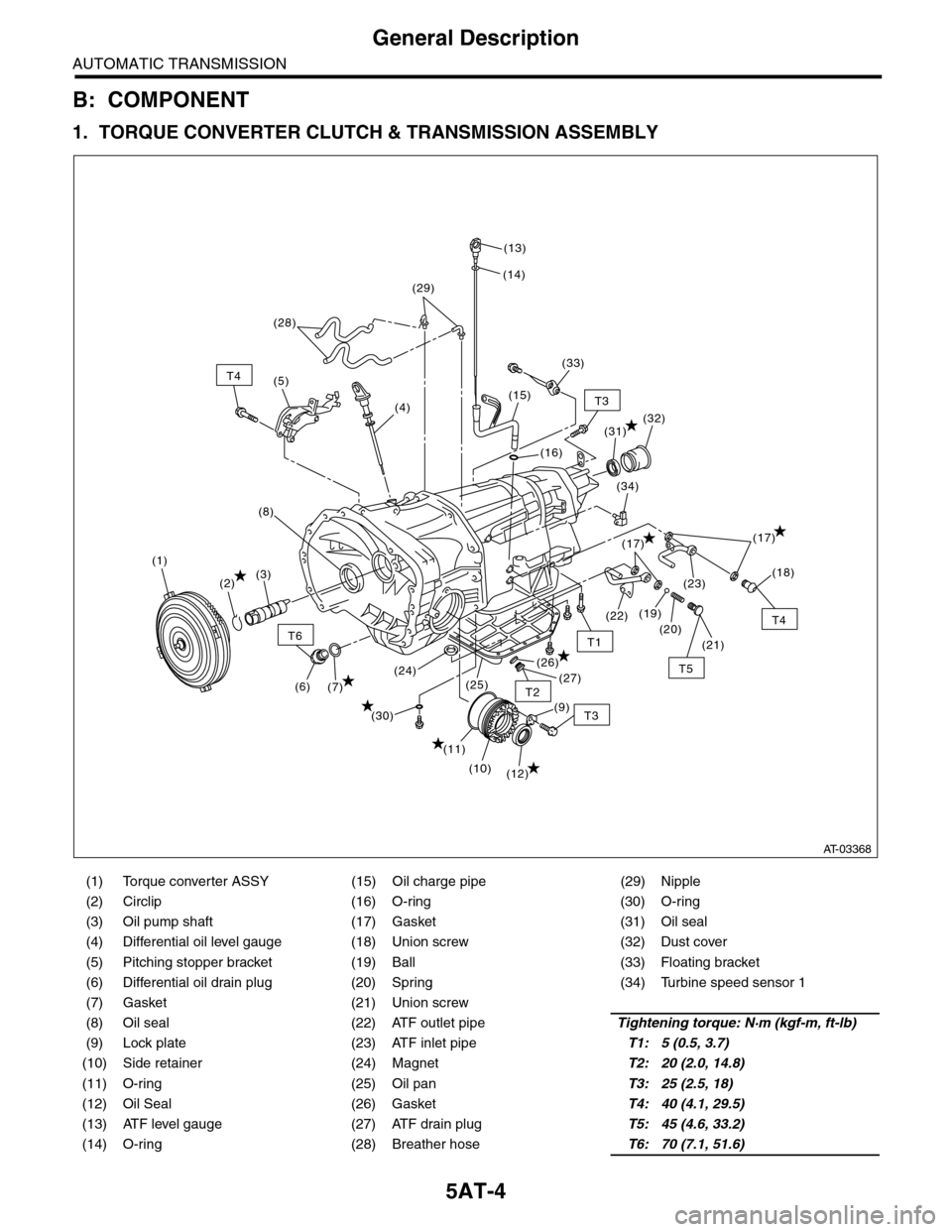
1. TORQUE CONVERTER CLUTCH & TRANSMISSION ASSEMBLY
(1) Torque converter ASSY (15) Oil charge pipe (29) Nipple
(2) Circlip (16) O-ring (30) O-ring
(3) Oil pump shaft (17) Gasket (31) Oil seal
(4) Differential oil level gauge (18) Union screw (32) Dust cover
(5) Pitching stopper bracket (19) Ball (33) Floating bracket
(6) Differential oil drain plug (20) Spring (34) Turbine speed sensor 1
(7) Gasket (21) Union screw
(8) Oil seal (22) ATF outlet pipeTightening torque: N·m (kgf-m, ft-lb)
(9) Lock plate (23) ATF inlet pipeT1: 5 (0.5, 3.7)
(10) Side retainer (24) MagnetT2: 20 (2.0, 14.8)
(11) O-ring (25) Oil panT3: 25 (2.5, 18)
(12) Oil Seal (26) GasketT4: 40 (4.1, 29.5)
(13) ATF level gauge (27) ATF drain plugT5: 45 (4.6, 33.2)
(14) O-ring (28) Breather hoseT6: 70 (7.1, 51.6)
T6
T4
T3
T5
T1
T2
T4
T3
(12)
(11)
(7)(6)
(10)
(21)
(20)
(23)
(26)
(25)(24)(27)
(30)
(19)(22)
(18)
(17)
(34)
(32)
(16)
(15)
(14)
(13)
(28)
(4)
(5)
(1)
(2)(3)
(8)
(29)
(33)
(31)
(9)
(17)
AT-03368
Page 2025 of 2453
5AT-9
General Description
AUTOMATIC TRANSMISSION
6. CONTROL VALVE & TRANSMISSION HARNESS
(1) Transmission harness ASSY (4) ClipTightening torque: N·m (kgf-m, ft-lb)
(3) Harness bracket (5) Control valve ASSYT1: 7(0.7, 5.2)
(2) Front vehicle speed sensor
(1)
(2)
(3)
(4)
(5)
T1
T1
T1
AT-03254
Page 2050 of 2453
5AT-34
Automatic Transmission Assembly
AUTOMATIC TRANSMISSION
9. Automatic Transmission As-
sembly
A: REMOVAL
1) Set the vehicle on a lift.
2) Open the front hood and support with the hood
stay.
3) Disconnect the ground cable from battery.
4) Remove the collector cover.
5) Remove the air intake chamber.
IN(H6DO)-6, REMOVAL, Air Intake Chamber.>
6) Remove the air breather hose.
REMOVAL, Air Breather Hose.>
7) Remove the starter.
MOVAL, Starter.>
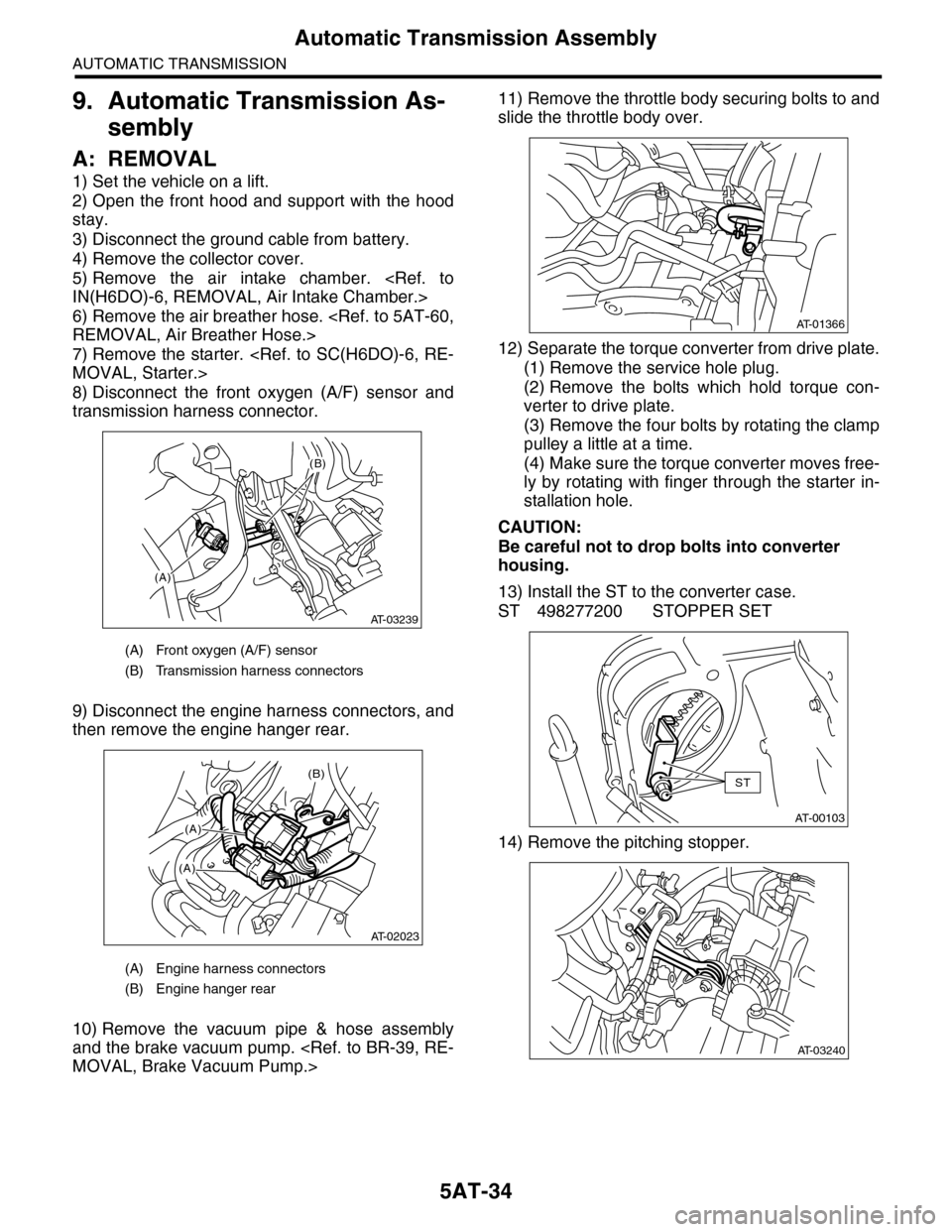
8) Disconnect the front oxygen (A/F) sensor and
transmission harness connector.
9) Disconnect the engine harness connectors, and
then remove the engine hanger rear.
10) Remove the vacuum pipe & hose assembly
and the brake vacuum pump.
MOVAL, Brake Vacuum Pump.>
11) Remove the throttle body securing bolts to and
slide the throttle body over.
12) Separate the torque converter from drive plate.
(1) Remove the service hole plug.
(2) Remove the bolts which hold torque con-
verter to drive plate.
(3) Remove the four bolts by rotating the clamp
pulley a little at a time.
(4) Make sure the torque converter moves free-
ly by rotating with finger through the starter in-
stallation hole.
CAUTION:
Be careful not to drop bolts into converter
housing.
13) Install the ST to the converter case.
ST 498277200 STOPPER SET
14) Remove the pitching stopper.
(A) Front oxygen (A/F) sensor
(B) Transmission harness connectors
(A) Engine harness connectors
(B) Engine hanger rear
(A)
(B)
AT-03239
(B)
(A)
(A)
AT-02023
AT-01366
AT-00103
ST
AT-03240
Page 2051 of 2453
5AT-35
Automatic Transmission Assembly
AUTOMATIC TRANSMISSION
15) Remove the pitching stopper bracket.
16) Set the ST.
ST1 41099AA010 ENGINE SUPPORT BRACK-
ET
ST2 41099AA020 ENGINE SUPPORT
17) Remove the transmission mounting bolt (upper
side).
18) Lift-up the vehicle.
19) Remove the under cover.
20) Remove the front exhaust pipe, rear exhaust
pipe and muffler.
AL, Front Exhaust Pipe.>
REMOVAL, Rear Exhaust Pipe.>
EX(H6DO)-8, REMOVAL, Muffler.>
21) Remove the heat shield cover.
22) Remove the ATF drain plug to drain ATF.
23) Remove the oil charge pipe.
24) Disconnect the connector from turbine speed
sensor 1.
AT-03241
AT-03242
ST2
ST1
AT-03237
(A) Oil pan
(B) Drain plug
AT-03243
(A)
AT-01361
(B)
AT-01371
AT-01642
Page 2052 of 2453
5AT-36
Automatic Transmission Assembly
AUTOMATIC TRANSMISSION
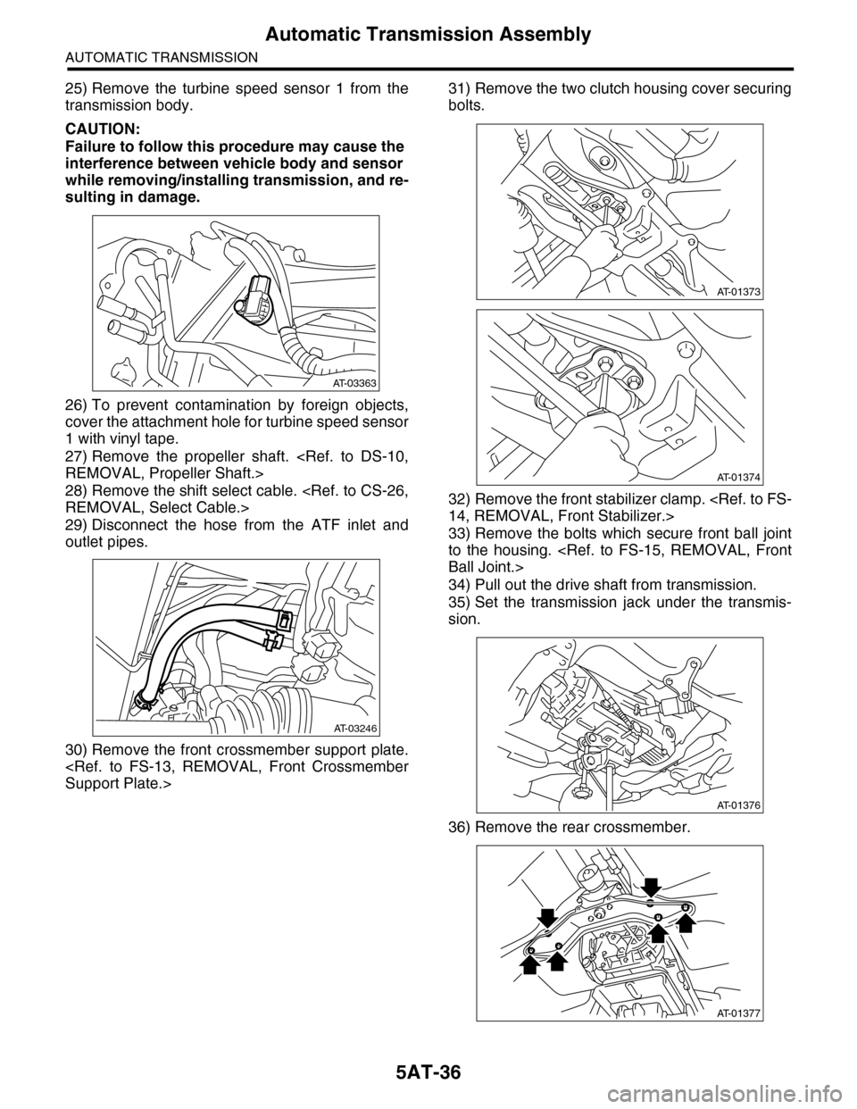
25) Remove the turbine speed sensor 1 from the
transmission body.
CAUTION:
Failure to follow this procedure may cause the
interference between vehicle body and sensor
while removing/installing transmission, and re-
sulting in damage.
26) To prevent contamination by foreign objects,
cover the attachment hole for turbine speed sensor
1 with vinyl tape.
27) Remove the propeller shaft.
REMOVAL, Propeller Shaft.>
28) Remove the shift select cable.
REMOVAL, Select Cable.>
29) Disconnect the hose from the ATF inlet and
outlet pipes.
30) Remove the front crossmember support plate.
Support Plate.>
31) Remove the two clutch housing cover securing
bolts.
32) Remove the front stabilizer clamp.
14, REMOVAL, Front Stabilizer.>
33) Remove the bolts which secure front ball joint
to the housing.
Ball Joint.>
34) Pull out the drive shaft from transmission.
35) Set the transmission jack under the transmis-
sion.
36) Remove the rear crossmember.
AT-03363
AT-03246
AT-01373
AT-01374
AT-01376
AT-01377
Page 2055 of 2453
5AT-39
Automatic Transmission Assembly
AUTOMATIC TRANSMISSION
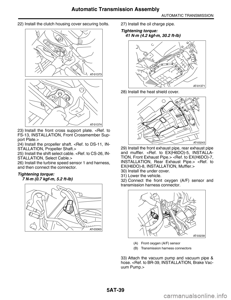
22) Install the clutch housing cover securing bolts.
23) Install the front cross support plate.
FS-13, INSTALLATION, Front Crossmember Sup-
port Plate.>
24) Install the propeller shaft.
STALLATION, Propeller Shaft.>
25) Install the shift select cable.
STALLATION, Select Cable.>
26) Install the turbine speed sensor 1 and harness,
and then connect the connector.
Tightening torque:
7 N·m (0.7 kgf-m, 5.2 ft-lb)
27) Install the oil charge pipe.
Tightening torque:
41 N·m (4.2 kgf-m, 30.2 ft-lb)
28) Install the heat shield cover.
29) Install the front exhaust pipe, rear exhaust pipe
and muffler.
TION, Front Exhaust Pipe.>
INSTALLATION, Rear Exhaust Pipe.>
EX(H6DO)-8, INSTALLATION, Muffler.>
30) Install the under cover.
31) Lower the vehicle.
32) Connect the front oxygen (A/F) sensor and
transmission harness connector.
33) Attach the vacuum pump and vacuum pipe &
hose.
uum Pump.>
AT-01373
AT-01374
AT-03363
(A) Front oxygen (A/F) sensor
(B) Transmission harness connectors
AT-01371
AT-03243
(A)
(B)
AT-03239
Page 2062 of 2453
5AT-46
Inhibitor Switch
AUTOMATIC TRANSMISSION
13.Inhibitor Switch
A: INSPECTION
Inhibitor switch cannot be checked, because the in-
hibitor switch is installed on control valve assembly.
When a malfunction occurs, refer to 5AT (diag)
section.
TRANSMISSION RANGE SENSOR CIRCUIT
(PRNDL INPUT), Diagnostic Procedure with Diag-
nostic Trouble Code (DTC).>
Page 2063 of 2453
5AT-47
Front Vehicle Speed Sensor
AUTOMATIC TRANSMISSION
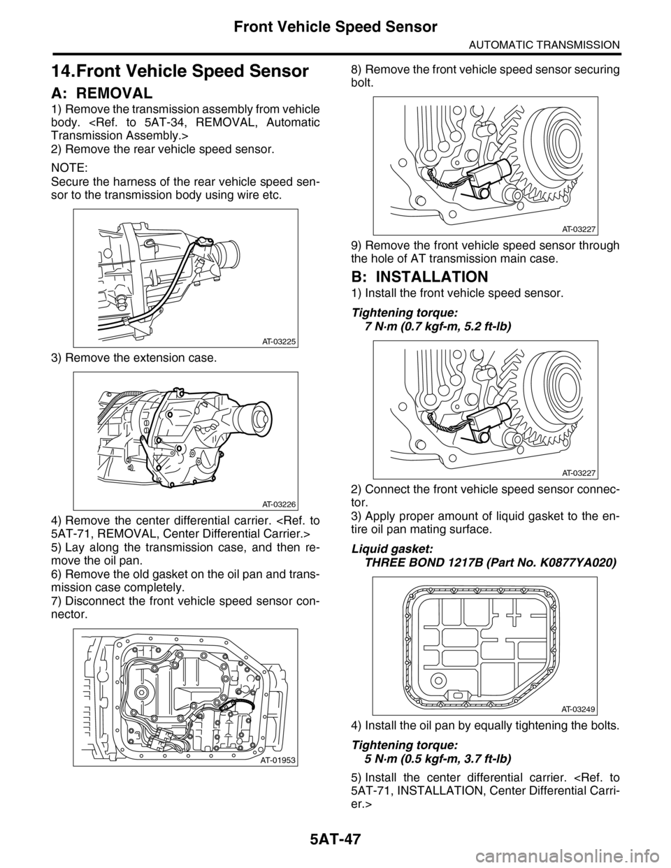
14.Front Vehicle Speed Sensor
A: REMOVAL
1) Remove the transmission assembly from vehicle
body.
Transmission Assembly.>
2) Remove the rear vehicle speed sensor.
NOTE:
Secure the harness of the rear vehicle speed sen-
sor to the transmission body using wire etc.
3) Remove the extension case.
4) Remove the center differential carrier.
5AT-71, REMOVAL, Center Differential Carrier.>
5) Lay along the transmission case, and then re-
move the oil pan.
6) Remove the old gasket on the oil pan and trans-
mission case completely.
7) Disconnect the front vehicle speed sensor con-
nector.
8) Remove the front vehicle speed sensor securing
bolt.
9) Remove the front vehicle speed sensor through
the hole of AT transmission main case.
B: INSTALLATION
1) Install the front vehicle speed sensor.
Tightening torque:
7 N·m (0.7 kgf-m, 5.2 ft-lb)
2) Connect the front vehicle speed sensor connec-
tor.
3) Apply proper amount of liquid gasket to the en-
tire oil pan mating surface.
Liquid gasket:
THREE BOND 1217B (Part No. K0877YA020)
4) Install the oil pan by equally tightening the bolts.
Tightening torque:
5 N·m (0.5 kgf-m, 3.7 ft-lb)
5) Install the center differential carrier.
5AT-71, INSTALLATION, Center Differential Carri-
er.>
AT-03225
AT-03226
AT-01953
AT-03227
AT-03227
AT-03249