Page 2064 of 2453
5AT-48
Front Vehicle Speed Sensor
AUTOMATIC TRANSMISSION
6) Install the extension case.
Tightening torque:
25 N·m (2.5 kgf-m, 18 ft-lb)
7) Install the rear vehicle speed sensor.
Tightening torque:
7 N·m (0.7 kgf-m, 5.2 ft-lb)
8) Install the transmission assembly to the vehicle.
Transmission Assembly.>
9) Pour ATF from the oil charge pipe.
26, REPLACEMENT, Automatic Transmission Flu-
id.>
10) Check the level and leaks of ATF.
26, INSPECTION, Automatic Transmission Fluid.>
AT-03226
AT-03225
Page 2065 of 2453
5AT-49
Rear Vehicle Speed Sensor
AUTOMATIC TRANSMISSION
15.Rear Vehicle Speed Sensor
A: REMOVAL
1) Set the vehicle on a lift.
2) Disconnect the ground cable from battery.
3) Remove the air intake chamber.
IN(H6DO)-6, REMOVAL, Air Intake Chamber.>
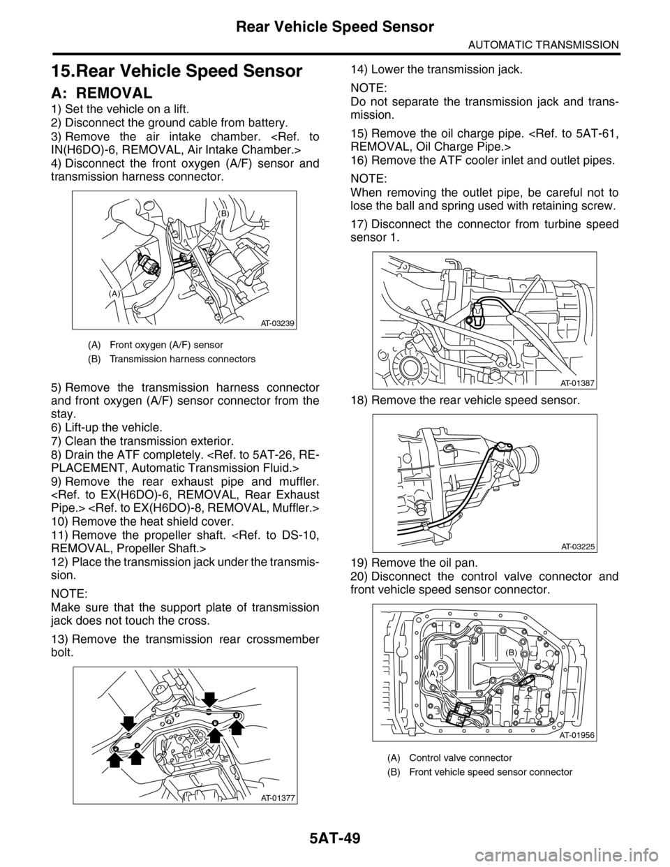
4) Disconnect the front oxygen (A/F) sensor and
transmission harness connector.
5) Remove the transmission harness connector
and front oxygen (A/F) sensor connector from the
stay.
6) Lift-up the vehicle.
7) Clean the transmission exterior.
8) Drain the ATF completely.
PLACEMENT, Automatic Transmission Fluid.>
9) Remove the rear exhaust pipe and muffler.
Pipe.>
10) Remove the heat shield cover.
11) Remove the propeller shaft.
REMOVAL, Propeller Shaft.>
12) Place the transmission jack under the transmis-
sion.
NOTE:
Make sure that the support plate of transmission
jack does not touch the cross.
13) Remove the transmission rear crossmember
bolt.
14) Lower the transmission jack.
NOTE:
Do not separate the transmission jack and trans-
mission.
15) Remove the oil charge pipe.
REMOVAL, Oil Charge Pipe.>
16) Remove the ATF cooler inlet and outlet pipes.
NOTE:
When removing the outlet pipe, be careful not to
lose the ball and spring used with retaining screw.
17) Disconnect the connector from turbine speed
sensor 1.
18) Remove the rear vehicle speed sensor.
19) Remove the oil pan.
20) Disconnect the control valve connector and
front vehicle speed sensor connector.
(A) Front oxygen (A/F) sensor
(B) Transmission harness connectors
(A)
(B)
AT-03239
AT-01377
(A) Control valve connector
(B) Front vehicle speed sensor connector
AT-01387
AT-03225
AT-01956
(B)
(A)
Page 2066 of 2453
5AT-50
Rear Vehicle Speed Sensor
AUTOMATIC TRANSMISSION
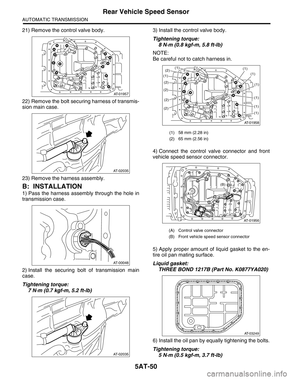
21) Remove the control valve body.
22) Remove the bolt securing harness of transmis-
sion main case.
23) Remove the harness assembly.
B: INSTALLATION
1) Pass the harness assembly through the hole in
transmission case.
2) Install the securing bolt of transmission main
case.
Tightening torque:
7 N·m (0.7 kgf-m, 5.2 ft-lb)
3) Install the control valve body.
Tightening torque:
8 N·m (0.8 kgf-m, 5.8 ft-lb)
NOTE:
Be careful not to catch harness in.
4) Connect the control valve connector and front
vehicle speed sensor connector.
5) Apply proper amount of liquid gasket to the en-
tire oil pan mating surface.
Liquid gasket:
THREE BOND 1217B (Part No. K0877YA020)
6) Install the oil pan by equally tightening the bolts.
Tightening torque:
5 N·m (0.5 kgf-m, 3.7 ft-lb)
AT-01957
AT-02035
AT-00048
AT-02035
(1) 58 mm (2.28 in)
(2) 65 mm (2.56 in)
(A) Control valve connector
(B) Front vehicle speed sensor connector
AT-01958
(1)(1)
(1)
(2)
(2)
(2)
(2)
(1)
(1)
(1)
(1)
(1)
(2)
AT-01956
(B)
(A)
AT-03249
Page 2067 of 2453
5AT-51
Rear Vehicle Speed Sensor
AUTOMATIC TRANSMISSION
7) Install the rear vehicle speed sensor and turbine
speed sensor 1, and then fasten the harness.
Tightening torque:
7 N·m (0.7 kgf-m, 5.2 ft-lb)
8) Install a new aluminum washer and oil cooler
pipe.
Tightening torque:
40 N·m (4.1 kgf-m, 29.5 ft-lb) (ATF inlet pipe)
45 N·m (4.6 kgf-m, 33.2 ft-lb) (ATF outlet pipe)
9) Install the oil charge pipe.
STALLATION, Oil Charge Pipe.>
10) Install the transmission rear crossmember bolt.
Tightening torque:
70 N·m (7.1 kgf-m, 51.6 ft-lb)
11) Install the propeller shaft.
STALLATION, Propeller Shaft.>
12) Install the heat shield cover.
13) Install the rear exhaust pipe and muffler.
to EX(H6DO)-7, INSTALLATION, Rear Exhaust
Pipe.>
Muffler.>
14) Lower the vehicle.
15) Install the transmission connector to the stay,
and then connect the connector.
16) Install the air intake chamber.
IN(H6DO)-6, INSTALLATION, Air Intake Cham-
ber.>
17) Pour ATF from the oil charge pipe.
5AT-26, REPLACEMENT, Automatic Transmis-
sion Fluid.>
18) Check the level and leaks of ATF.
26, INSPECTION, Automatic Transmission Fluid.>
Page 2068 of 2453
5AT-52
Turbine Speed Sensor 1
AUTOMATIC TRANSMISSION
16.Turbine Speed Sensor 1
A: REMOVAL
1) Remove the air intake chamber.
IN(H6DO)-6, REMOVAL, Air Intake Chamber.>
2) Lift-up the vehicle.
3) Disconnect the turbine speed sensor 1 connec-
tor.
4) Remove the turbine speed sensor 1.
B: INSTALLATION
1) Install the turbine speed sensor 1.
Tightening torque:
7 N·m (0.7 kgf-m, 5.2 ft-lb)
2) Connect the turbine speed sensor 1 connector.
3) Lower the vehicle.
4) Install the air intake chamber.
IN(H6DO)-6, INSTALLATION, Air Intake Cham-
ber.>
AT-01387
AT-01387
Page 2069 of 2453
5AT-53
Control Valve Body
AUTOMATIC TRANSMISSION
17.Control Valve Body
A: REMOVAL
1) Set the vehicle on a lift.
2) Disconnect the ground cable from battery.
3) Lift-up the vehicle.
4) Clean the transmission exterior.
5) Remove the ATF drain plug to drain ATF.
CAUTION:
Immediately after the vehicle has been running
or after idling for a long time, the ATF will be
hot. Be careful not to burn yourself.
6) Tighten the ATF drain plug.
NOTE:
Use a new gasket.
Tightening torque:
20 N·m (2.0 kgf-m, 14.8 ft-lb)
7) Remove the oil pan.
CAUTION:
Be sure to prevent the entering of dust and oth-
er foreign matters into oil pan.
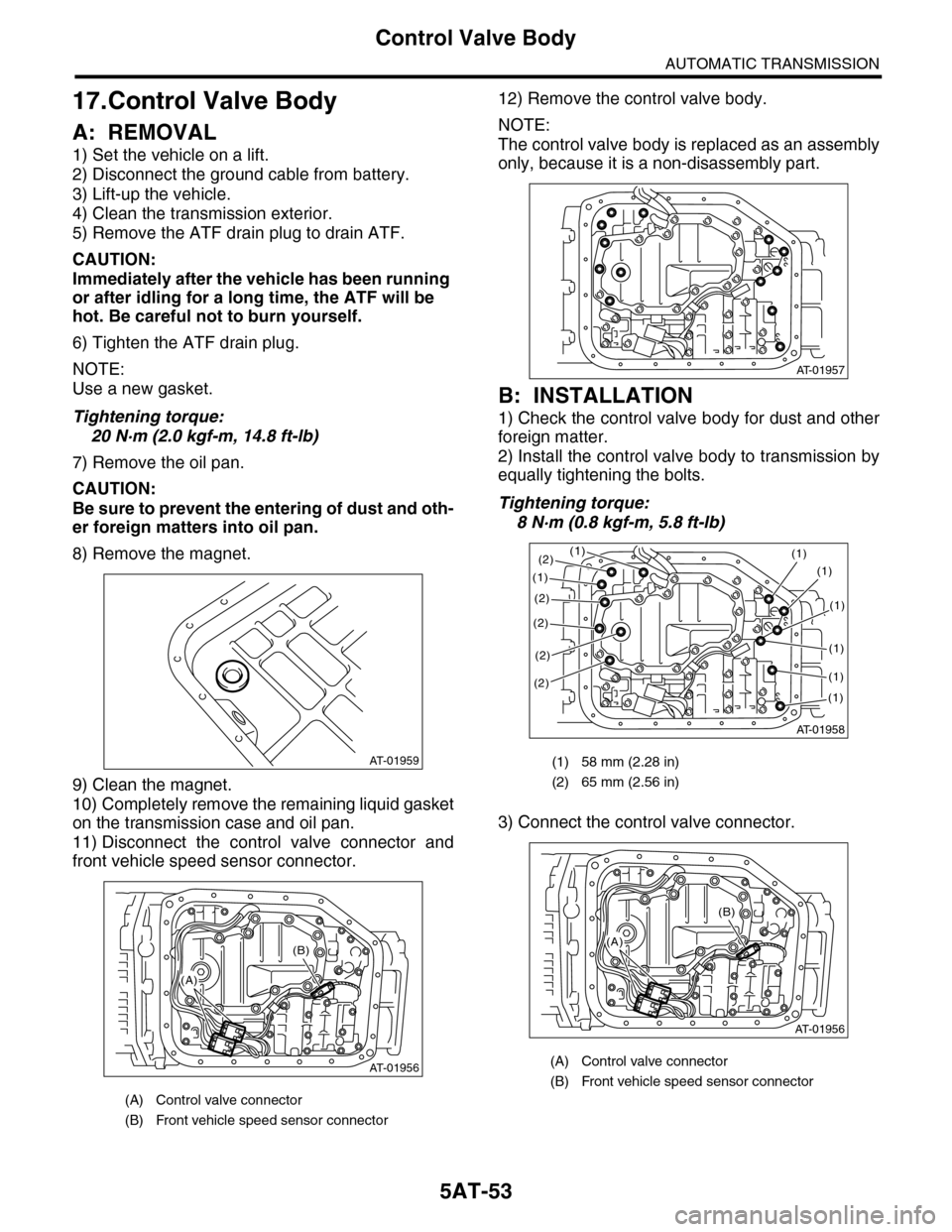
8) Remove the magnet.
9) Clean the magnet.
10) Completely remove the remaining liquid gasket
on the transmission case and oil pan.
11) Disconnect the control valve connector and
front vehicle speed sensor connector.
12) Remove the control valve body.
NOTE:
The control valve body is replaced as an assembly
only, because it is a non-disassembly part.
B: INSTALLATION
1) Check the control valve body for dust and other
foreign matter.
2) Install the control valve body to transmission by
equally tightening the bolts.
Tightening torque:
8 N·m (0.8 kgf-m, 5.8 ft-lb)
3) Connect the control valve connector.
(A) Control valve connector
(B) Front vehicle speed sensor connector
AT-01959
AT-01956
(B)
(A)
(1) 58 mm (2.28 in)
(2) 65 mm (2.56 in)
(A) Control valve connector
(B) Front vehicle speed sensor connector
AT-01957
AT-01958
(1)(1)
(1)
(2)
(2)
(2)
(2)
(1)
(1)
(1)
(1)
(1)
(2)
AT-01956
(B)
(A)
Page 2079 of 2453
5AT-63
Extension Case
AUTOMATIC TRANSMISSION
24.Extension Case
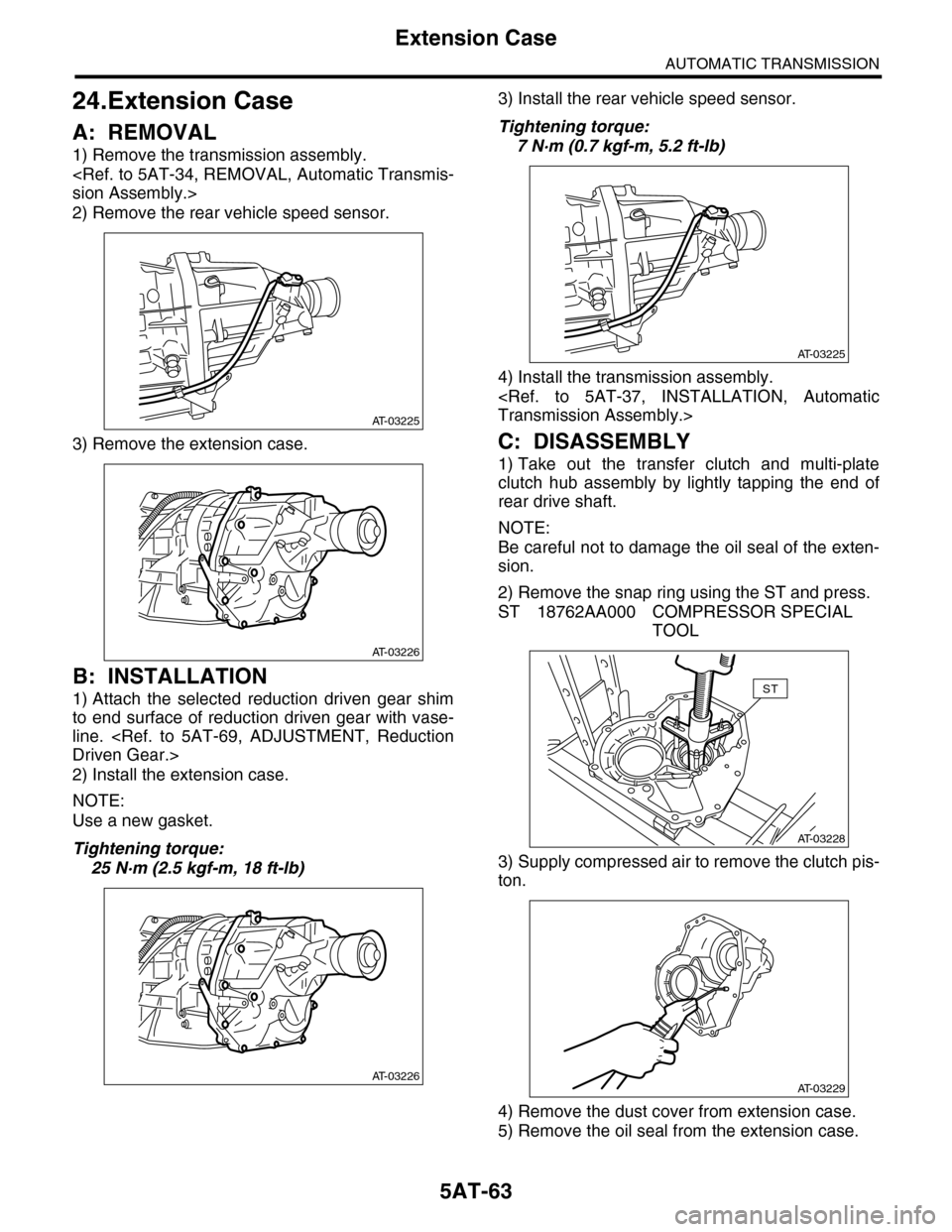
A: REMOVAL
1) Remove the transmission assembly.
sion Assembly.>
2) Remove the rear vehicle speed sensor.
3) Remove the extension case.
B: INSTALLATION
1) Attach the selected reduction driven gear shim
to end surface of reduction driven gear with vase-
line.
Driven Gear.>
2) Install the extension case.
NOTE:
Use a new gasket.
Tightening torque:
25 N·m (2.5 kgf-m, 18 ft-lb)
3) Install the rear vehicle speed sensor.
Tightening torque:
7 N·m (0.7 kgf-m, 5.2 ft-lb)
4) Install the transmission assembly.
Transmission Assembly.>
C: DISASSEMBLY
1) Take out the transfer clutch and multi-plate
clutch hub assembly by lightly tapping the end of
rear drive shaft.
NOTE:
Be careful not to damage the oil seal of the exten-
sion.
2) Remove the snap ring using the ST and press.
ST 18762AA000 COMPRESSOR SPECIAL
TOOL
3) Supply compressed air to remove the clutch pis-
ton.
4) Remove the dust cover from extension case.
5) Remove the oil seal from the extension case.
AT-03225
AT-03226
AT-03226
AT-03225
AT-03228
ST
AT-03229
Page 2083 of 2453
5AT-67
Rear Drive Shaft
AUTOMATIC TRANSMISSION
26.Rear Drive Shaft
A: REMOVAL
1) Remove the transmission assembly from vehicle
body.
Transmission Assembly.>
2) Remove the rear vehicle speed sensor, and then
remove the extension case.
MOVAL, Extension Case.>
3) Pull out the rear driveshaft from center differen-
tial assembly.
4) Remove the drive plate and driven plate.
B: INSTALLATION
1) Select the shim.
MENT, Transfer Clutch.>
2) Install drive plate and driven plate.
3) Insert the rear driveshaft into the center differen-
tial assembly.
4) Combine the extension case, and then install the
rear vehicle speed sensor.
STALLATION, Extension Case.>
5) Install the transmission assembly to the vehicle.
Transmission Assembly.>
C: DISASSEMBLY
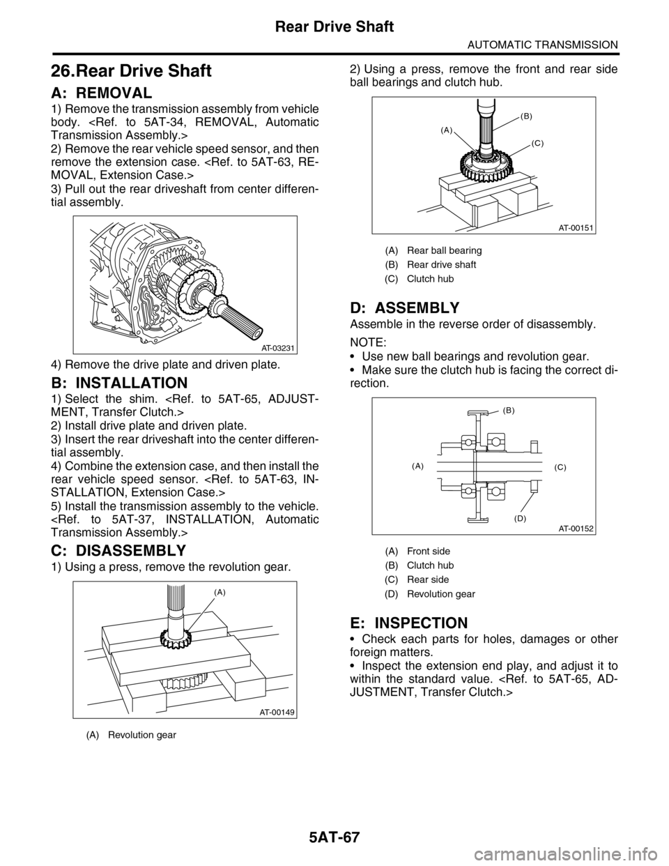
1) Using a press, remove the revolution gear.
2) Using a press, remove the front and rear side
ball bearings and clutch hub.
D: ASSEMBLY
Assemble in the reverse order of disassembly.
NOTE:
•Use new ball bearings and revolution gear.
•Make sure the clutch hub is facing the correct di-
rection.
E: INSPECTION
•Check each parts for holes, damages or other
foreign matters.
•Inspect the extension end play, and adjust it to
within the standard value.
JUSTMENT, Transfer Clutch.>
(A) Revolution gear
AT-03231
AT-00149
(A)
(A) Rear ball bearing
(B) Rear drive shaft
(C) Clutch hub
(A) Front side
(B) Clutch hub
(C) Rear side
(D) Revolution gear
AT-00151
(A)
(B)
(C)
AT-00152
(A)
(B)
(C)
(D)