2009 SUBARU TRIBECA fuel pressure
[x] Cancel search: fuel pressurePage 1644 of 2453
GD(H6DO)-32
Diagnostic Trouble Code (DTC) Detecting Criteria
GENERAL DESCRIPTION
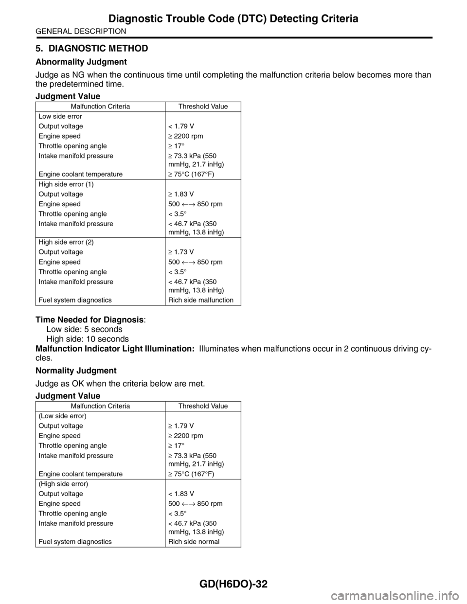
5. DIAGNOSTIC METHOD
Abnormality Judgment
Judge as NG when the continuous time until completing the malfunction criteria below becomes more than
the predetermined time.
Time Needed for Diagnosis:
Low side: 5 seconds
High side: 10 seconds
Malfunction Indicator Light Illumination: Illuminates when malfunctions occur in 2 continuous driving cy-
cles.
Normality Judgment
Judge as OK when the criteria below are met.
Judgment Value
Malfunction Criteria Threshold Value
Low side error
Output voltage < 1.79 V
Engine speed≥ 2200 rpm
Throttle opening angle≥ 17°
Intake manifold pressure≥ 73.3 kPa (550
mmHg, 21.7 inHg)
Engine coolant temperature≥ 75°C (167°F)
High side error (1)
Output voltage≥ 1.83 V
Engine speed 500 ←→ 850 rpm
Throttle opening angle < 3.5°
Intake manifold pressure < 46.7 kPa (350
mmHg, 13.8 inHg)
High side error (2)
Output voltage≥ 1.73 V
Engine speed 500 ←→ 850 rpm
Throttle opening angle < 3.5°
Intake manifold pressure < 46.7 kPa (350
mmHg, 13.8 inHg)
Fuel system diagnostics Rich side malfunction
Judgment Value
Malfunction Criteria Threshold Value
(Low side error)
Output voltage≥ 1.79 V
Engine speed≥ 2200 rpm
Throttle opening angle≥ 17°
Intake manifold pressure≥ 73.3 kPa (550
mmHg, 21.7 inHg)
Engine coolant temperature≥ 75°C (167°F)
(High side error)
Output voltage < 1.83 V
Engine speed 500 ←→ 850 rpm
Throttle opening angle < 3.5°
Intake manifold pressure < 46.7 kPa (350
mmHg, 13.8 inHg)
Fuel system diagnostics Rich side normal
Page 1679 of 2453
GD(H6DO)-67
Diagnostic Trouble Code (DTC) Detecting Criteria
GENERAL DESCRIPTION
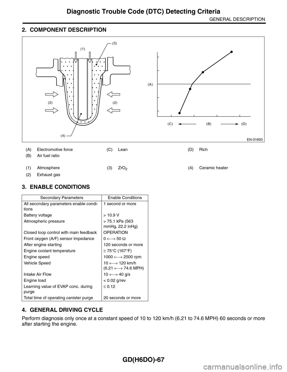
2. COMPONENT DESCRIPTION
3. ENABLE CONDITIONS
4. GENERAL DRIVING CYCLE
Perform diagnosis only once at a constant speed of 10 to 120 km/h (6.21 to 74.6 MPH) 60 seconds or more
after starting the engine.
(A) Electromotive force (C) Lean (D) Rich
(B) Air fuel ratio
(1) Atmosphere (3) ZrO2(4) Ceramic heater
(2) Exhaust gas
Secondary Parameters Enable Conditions
All secondary parameters enable condi-
tions
1 second or more
Battery voltage > 10.9 V
Atmospheric pressure > 75.1 kPa (563
mmHg, 22.2 inHg)
Closed loop control with main feedback OPERATION
Fr o nt ox yg e n ( A / F) s en so r im pe d an c e 0 ←→ 50 Ω
After engine starting 120 seconds or more
Engine coolant temperature≥ 75°C (167°F)
Engine speed 1000 ←→ 2500 rpm
Ve h i c l e S p e e d 1 0 ←→ 120 km/h
(6.21 ←→ 74.6 MPH)
Intake Air Flow 10 ←→ 40 g/s
Engine load < 0.02 g/rev
Learning value of EVAP conc. during
purge
≤ 0.12
To t a l t i m e o f o p e r a t i n g c a n i s t e r p u r g e 2 0 s e c o n d s o r m o r e
(1)
(2)
(4)
(2)
(3)
EN-01693
(C) (B) (D)
(A)
Page 1697 of 2453
GD(H6DO)-85
Diagnostic Trouble Code (DTC) Detecting Criteria
GENERAL DESCRIPTION
BB:DTC P0172 SYSTEM TOO RICH (BANK 1)
1. OUTLINE OF DIAGNOSIS
Detect fuel system malfunction by the amount of main feedback control.
Diagnostic method
Fuel system is diagnosed by comparing the target air fuel ratio calculated by ECM with the actual air fuel ra-
tio measured by sensor.
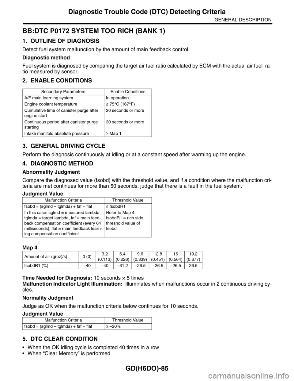
2. ENABLE CONDITIONS
3. GENERAL DRIVING CYCLE
Perform the diagnosis continuously at idling or at a constant speed after warming up the engine.
4. DIAGNOSTIC METHOD
Abnormality Judgment
Compare the diagnosed value (fsobd) with the threshold value, and if a condition where the malfunction cri-
teria are met continues for more than 50 seconds, judge that there is a fault in the fuel system.
Time Needed for Diagnosis: 10 seconds × 5 times
Malfunction Indicator Light Illumination: Illuminates when malfunctions occur in 2 continuous driving cy-
cles.
Normality Judgment
Judge as OK when the malfunction criteria below continues for 10 seconds.
5. DTC CLEAR CONDITION
•When the OK idling cycle is completed 40 times in a row
•When “Clear Memory” is performed
Secondary Parameters Enable Conditions
A/F main learning system In operation
Engine coolant temperature≥ 75°C (167°F)
Cumulative time of canister purge after
engine start
20 seconds or more
Continuous period after canister purge
starting
30 seconds or more
Intake manifold absolute pressure≥ Map 1
Judgment Value
Malfunction Criteria Threshold Value
fsobd = (sglmd – tglmda) + faf + flaf≤ fsobdR1
In this case: sglmd = measured lambda,
tglmda = target lambda, faf = main feed-
back compensation coefficient (every 64
milliseconds), flaf = main feedback learn-
ing compensation coefficient
Refer to Map 4.
fsobdR1 = rich side
threshold value of
fsobd
Map 4
Amount of air (g(oz)/s) 0 (0)3.2
(0.113)
6.4
(0.226)
9.6
(0.339)
12.8
(0.451)
16
(0.564)
19.2
(0.677)
fsobdR1 (%) –40 –40 –31.2 –26.5 –26.5 –26.5 26.5
Judgment Value
Malfunction Criteria Threshold Value
fsobd = (sglmd – tglmda) + faf + flaf≥ –20%
Page 1716 of 2453
GD(H6DO)-104
Diagnostic Trouble Code (DTC) Detecting Criteria
GENERAL DESCRIPTION
BN:DTC P0301 CYLINDER 1 MISFIRE DETECTED
1. OUTLINE OF DIAGNOSIS
Detect the presence of misfire occurrence. (Revolution fluctuation method)
Monitoring Misfire which influences exhaust deterioration (1.5 times of FTP) and catalyst damage is made
obligatory by the law. Misfire affecting these two has three patterns below. Intermittent misfire (Different cyl-
inders misfire intermittently.):
•Intermittent misfire (The same cylinder misfires in random, or different cylinders misfire in random.): FTP
1.5 times misfire
•Every time misfire (The same cylinder misfires every time.): FTP 1.5 times misfire, Catalyst damage misfire
The following detecting methods are adopted for these detection.
1) Intermittent misfire: FTP 1.5 times misfire
•120° Interval Difference Method
•360° Interval Difference Method (whole range)
•720° Interval Difference Method (3,000 rpm or less)
2) Misfire every time: FTP 1.5 times misfire, Catalyst damage misfire
•360° Interval Difference Method
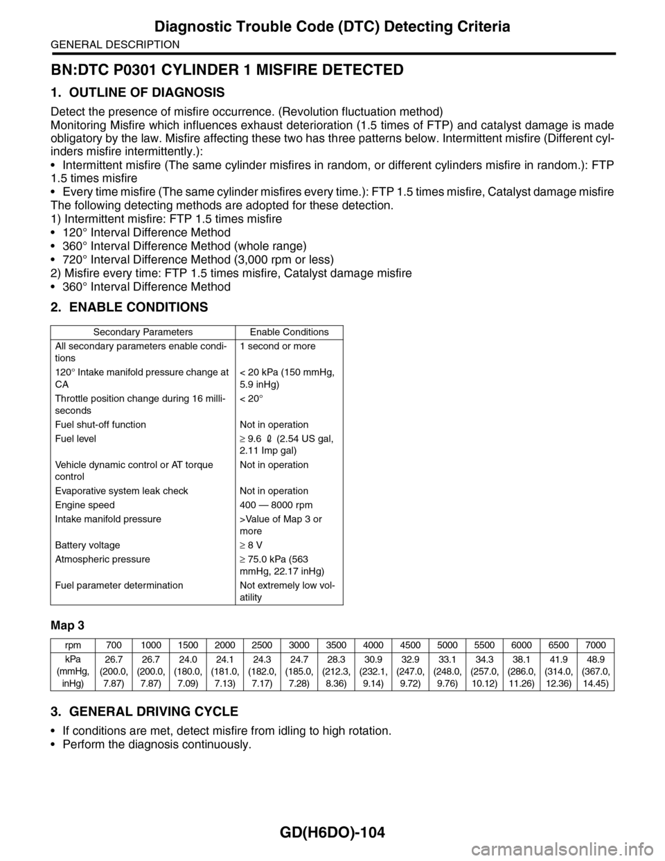
2. ENABLE CONDITIONS
Map 3
3. GENERAL DRIVING CYCLE
•If conditions are met, detect misfire from idling to high rotation.
•Perform the diagnosis continuously.
Secondary Parameters Enable Conditions
All secondary parameters enable condi-
tions
1 second or more
120° Intake manifold pressure change at
CA
< 20 kPa (150 mmHg,
5.9 inHg)
Throttle position change during 16 milli-
seconds
< 20°
Fuel shut-off function Not in operation
Fuel level≥ 9.6 2 (2.54 US gal,
2.11 Imp gal)
Ve h i c l e d y n a m i c c o n t r o l o r AT t o r q u e
control
Not in operation
Evaporative system leak check Not in operation
Engine speed 400 — 8000 rpm
Intake manifold pressure >Value of Map 3 or
more
Battery voltage≥ 8 V
Atmospheric pressure≥ 75.0 kPa (563
mmHg, 22.17 inHg)
Fuel parameter determination Not extremely low vol-
atility
rpm 700 1000 1500 2000 2500 3000 3500 4000 4500 5000 5500 6000 6500 7000
kPa
(mmHg,
inHg)
26.7
(200.0,
7.87)
26.7
(200.0,
7.87)
24.0
(180.0,
7.09)
24.1
(181.0,
7.13)
24.3
(182.0,
7.17)
24.7
(185.0,
7.28)
28.3
(212.3,
8.36)
30.9
(232.1,
9.14)
32.9
(247.0,
9.72)
33.1
(248.0,
9.76)
34.3
(257.0,
10.12)
38.1
(286.0,
11.26)
41.9
(314.0,
12.36)
48.9
(367.0,
14.45)
Page 1734 of 2453
GD(H6DO)-122
Diagnostic Trouble Code (DTC) Detecting Criteria
GENERAL DESCRIPTION
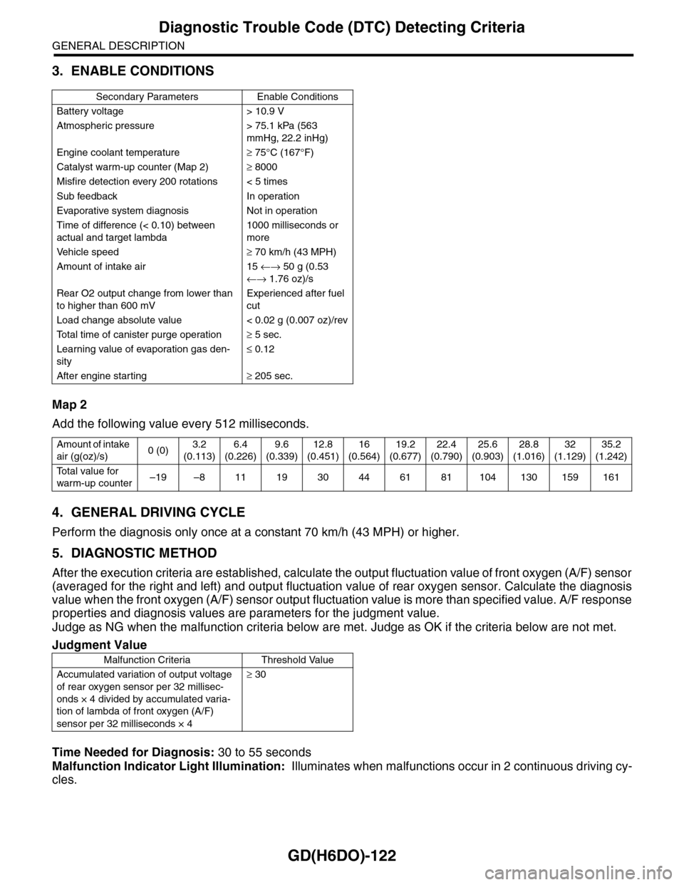
3. ENABLE CONDITIONS
Map 2
Add the following value every 512 milliseconds.
4. GENERAL DRIVING CYCLE
Perform the diagnosis only once at a constant 70 km/h (43 MPH) or higher.
5. DIAGNOSTIC METHOD
After the execution criteria are established, calculate the output fluctuation value of front oxygen (A/F) sensor
(averaged for the right and left) and output fluctuation value of rear oxygen sensor. Calculate the diagnosis
value when the front oxygen (A/F) sensor output fluctuation value is more than specified value. A/F response
properties and diagnosis values are parameters for the judgment value.
Judge as NG when the malfunction criteria below are met. Judge as OK if the criteria below are not met.
Time Needed for Diagnosis: 30 to 55 seconds
Malfunction Indicator Light Illumination: Illuminates when malfunctions occur in 2 continuous driving cy-
cles.
Secondary Parameters Enable Conditions
Battery voltage > 10.9 V
Atmospheric pressure > 75.1 kPa (563
mmHg, 22.2 inHg)
Engine coolant temperature≥ 75°C (167°F)
Catalyst warm-up counter (Map 2)≥ 8000
Misfire detection every 200 rotations < 5 times
Sub feedback In operation
Evaporative system diagnosis Not in operation
Time of difference (< 0.10) between
actual and target lambda
1000 milliseconds or
more
Ve h i c l e s p e e d≥ 70 km/h (43 MPH)
Amount of intake air 15 ←→ 50 g (0.53
←→ 1.76 oz)/s
Rear O2 output change from lower than
to higher than 600 mV
Experienced after fuel
cut
Load change absolute value < 0.02 g (0.007 oz)/rev
To t a l t i m e o f c a n i s t e r p u r g e o p e r a t i o n≥ 5 sec.
Learning value of evaporation gas den-
sity
≤ 0.12
After engine starting≥ 205 sec.
Amount of intake
air (g(oz)/s)0 (0)3.2
(0.113)
6.4
(0.226)
9.6
(0.339)
12.8
(0.451)
16
(0.564)
19.2
(0.677)
22.4
(0.790)
25.6
(0.903)
28.8
(1.016)
32
(1.129)
35.2
(1.242)
To t a l v a l u e f o r
warm-up counter–19 –8 11 19 30 44 61 81 104 130 159 161
Judgment Value
Malfunction Criteria Threshold Value
Accumulated variation of output voltage
of rear oxygen sensor per 32 millisec-
onds × 4 divided by accumulated varia-
tion of lambda of front oxygen (A/F)
sensor per 32 milliseconds × 4
≥ 30
Page 1736 of 2453
GD(H6DO)-124
Diagnostic Trouble Code (DTC) Detecting Criteria
GENERAL DESCRIPTION
CC:DTC P0442 EVAPORATIVE EMISSION CONTROL SYSTEM LEAK DETECT-
ED (SMALL LEAK)
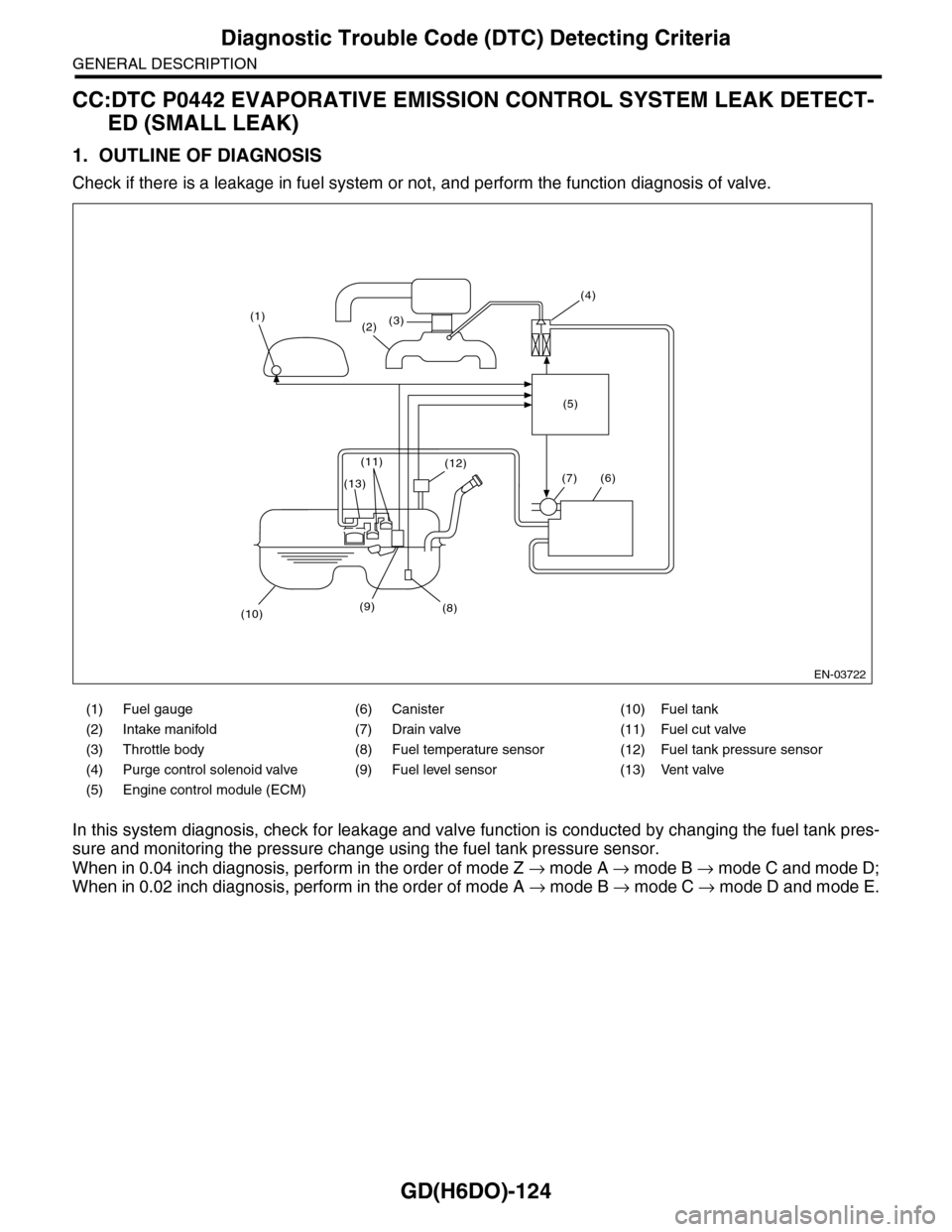
1. OUTLINE OF DIAGNOSIS
Check if there is a leakage in fuel system or not, and perform the function diagnosis of valve.
In this system diagnosis, check for leakage and valve function is conducted by changing the fuel tank pres-
sure and monitoring the pressure change using the fuel tank pressure sensor.
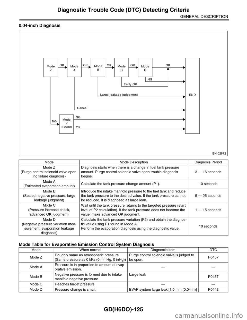
When in 0.04 inch diagnosis, perform in the order of mode Z → mode A → mode B → mode C and mode D;
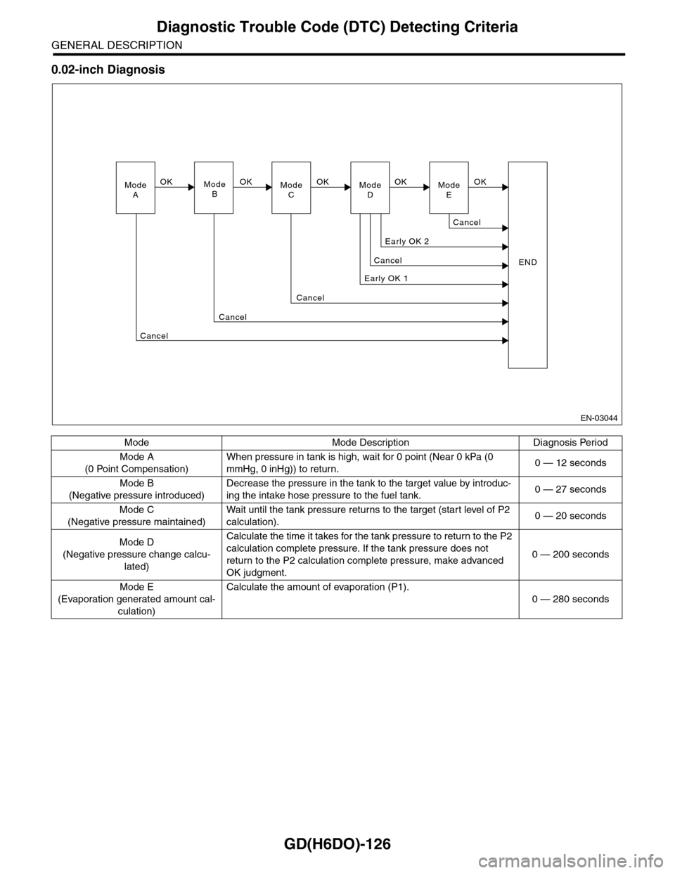
When in 0.02 inch diagnosis, perform in the order of mode A → mode B → mode C → mode D and mode E.
(1) Fuel gauge (6) Canister (10) Fuel tank
(2) Intake manifold (7) Drain valve (11) Fuel cut valve
(3) Throttle body (8) Fuel temperature sensor (12) Fuel tank pressure sensor
(4) Purge control solenoid valve (9) Fuel level sensor (13) Vent valve
(5) Engine control module (ECM)
EN-03722
(1)(2)(3)
(4)
(5)
(6)
(8)
(12)
(9)(10)
(13)
(11)
(7)
Page 1737 of 2453
GD(H6DO)-125
Diagnostic Trouble Code (DTC) Detecting Criteria
GENERAL DESCRIPTION
0.04-inch Diagnosis
Mode Mode Description Diagnosis Period
Mode Z
(Purge control solenoid valve open-
ing failure diagnosis)
Diagnosis starts when there is a change in fuel tank pressure
amount. Purge control solenoid valve open trouble diagnosis
begins.
3 — 16 seconds
Mode A
(Estimated evaporation amount)Calculate the tank pressure change amount (P1). 10 seconds
Mode B
(Sealed negative pressure, large
leakage judgment)
Introduce the intake manifold pressure to the fuel tank and reduce
the tank pressure to the desired value. If the tank pressure cannot
be reduced, it is diagnosed as large leak.
5 — 25 seconds
Mode C
(Pressure increase check,
advanced OK judgment)
Wait until the tank pressure retur ns to the targeted pressure (star t
level of P2 calculation). If the tank pressure does not become the
value, make advanced OK judgment.
1 — 15 seconds
Mode D
(Negative pressure variation mea-
surement, evaporation leakage
diagnosis)
Calculate the tank pressure variation (P2) and obtain the diagnos-
tic value using P1 found in Mode A.
Pe r fo r m t he eva po ra ti o n d ia g no si s u si n g t h e d ia g no st i c val u e.10 seconds
Mode Table for Evaporative Emission Control System Diagnosis
Mode When normal Diagnostic item DTC
Mode ZRoughly same as atmospheric pressure
(Same pressure as 0 kPa (0 mmHg, 0 inHg))
Purge control solenoid valve is judged to
be open.P0457
Mode APressure is in proportion to amount of evap-
orative emission.——
Mode BNegative pressure is formed due to intake
manifold negative pressure
Large leakP0457
Mode C Reaches target pressure — —
Mode D Pressure change is small. EVAP system large leak [1.0 mm (0.04 in)] P0442
ModeZModeAModeBModeCModeD
OKOKOKOKOK
NG
Early OK
Large leakage judgement
Cancel
ModeZExtend
NG
NG
OK
END
EN-02872
Page 1738 of 2453
GD(H6DO)-126
Diagnostic Trouble Code (DTC) Detecting Criteria
GENERAL DESCRIPTION
0.02-inch Diagnosis
Mode Mode Description Diagnosis Period
Mode A
(0 Point Compensation)
When pressure in tank is high, wait for 0 point (Near 0 kPa (0
mmHg, 0 inHg)) to return.0 — 12 seconds
Mode B
(Negative pressure introduced)
Decrease the pressure in the tank to the target value by introduc-
ing the intake hose pressure to the fuel tank.0 — 27 seconds
Mode C
(Negative pressure maintained)
Wa i t u nt i l t h e t a nk pr e ss ur e r et u r ns to t he t ar g e t ( s ta r t leve l o f P 2
calculation).0 — 20 seconds
Mode D
(Negative pressure change calcu-
lated)
Calculate the time it takes for the tank pressure to return to the P2
calculation complete pressure. If the tank pressure does not
return to the P2 calculation complete pressure, make advanced
OK judgment.
0 — 200 seconds
Mode E
(Evaporation generated amount cal-
culation)
Calculate the amount of evaporation (P1).
0 — 280 seconds
EN-03044
ModeAModeBModeCModeD
OKOKOK
Early OK 1
Cancel
Cancel
END
Cancel
Cancel
Early OK 2
OKModeE
Cancel
OK