Page 1563 of 2453
FU(H6DO)-2
General Description
FUEL INJECTION (FUEL SYSTEMS)
1. General Description
A: SPECIFICATION
Fuel tankCapacity 64 2 (16.9 US gal, 14.1 Imp gal)
Location Rear floor bottom
Fuel pump
Ty p e I m p e l l e r
Shutoff discharge pressure550 — 850 kPa (5.61 — 8.67 kg/cm2, 79.8 — 123.3 psi)
Discharge rate155 2 (41 US gal, 34.1 Imp gal)/h or more
[12 V at 300 kPa (3.06 kg/cm2, 43.5 psi)]
Fuel filterIn-tank type
Page 1565 of 2453
FU(H6DO)-4
General Description
FUEL INJECTION (FUEL SYSTEMS)
2. FUEL INJECTOR
(1) Intake manifold (8) HoseTightening torque: N·m (kgf-m, ft-lb)
(2) O-ring (9) NippleT1: 1.5 (0.15, 1.1)
(3) Manifold absolute pressure sensor (10) PlugT2: 6.4 (0.65, 4.7)
(4) Filter (11) Fuel pipe protector LHT3: 17 (1.7, 12.5)
(5) Fuel pipe protector RH (12) Fuel pipe ASSYT4: 19 (1.9, 14)
(6) Purge control solenoid valve (13) HoseT5: 25 (2.5, 18)
(7) Hose (14) Clamp
(1) Fuel injector pipe LH (4) Injection rubberTightening torque: N·m (kgf-m, ft-lb)
(2) Insulator (5) O-ringT: 19 (1.9, 14)
(3) Fuel injector (6) Fuel injector pipe RH
FU-02561
(6)
T
T
(5)
(4)
(3)
(2)
(2)(3)(4)(5)
(1)
Page 1567 of 2453
FU(H6DO)-6
General Description
FUEL INJECTION (FUEL SYSTEMS)
4. CRANKSHAFT POSITION, CAMSHAFT POSITION AND KNOCK SENSORS
(1) Crankshaft position sensor (6) Variable valve lift diagnosis oil
pressure switch RH
Tightening torque: N·m (kgf-m, ft-lb)
(2) Knock sensor RHT1: 6.4 (0.65, 4.7)
(3) Knock sensor LH (7) Variable valve lift diagnosis oil
pressure switch LH
T2: 17 (1.7, 12.5)
(4) Camshaft position sensor RHT3: 18 (1.8, 13.3)
(5) Camshaft position sensor LH (8) Oil temperature sensorT4: 25 (2.5, 18)
FU-02110
(6)
(4)
T2
T1
(3)
T4
(1)
(8)
T1
T3
(5)
T1
(2)
T4
(7)
T2
Page 1570 of 2453
FU(H6DO)-9
General Description
FUEL INJECTION (FUEL SYSTEMS)
6. FUEL LINE
(1) Clamp (8) Fuel pipe ASSY (15) Ring
(2) Evaporation hose A (9) Grommet (16) Fuel filler cap
(3) Fuel delivery hose A (10) Drain valve (17) Fuel tank pressure sensor
(4) Fuel pipe ASSY (11) Canister
(5) Evaporation hose B (12) ClampTightening torque: N·m (kgf-m, ft-lb)
(6) Fuel delivery hose B (13) Fuel filler pipeT1: 7.5 (0.76, 5.5)
(7) Clamp (14) Packing
C
C
A
AB
B
(15)
(13)(17)
(16)
(14)
T1
T2
(5)
(6)
(4)
(7)(7)
(8)
(9)
(11)
(12)
(12)
(10)
(2)
(3)(1)
FU-02678
Page 1573 of 2453

FU(H6DO)-12
Intake Manifold
FUEL INJECTION (FUEL SYSTEMS)
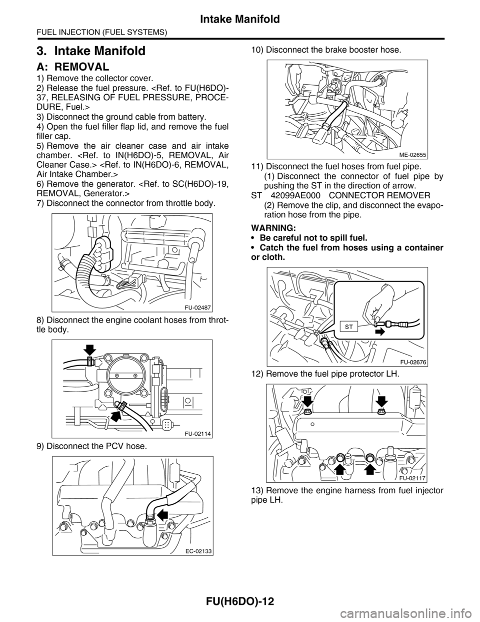
3. Intake Manifold
A: REMOVAL
1) Remove the collector cover.
2) Release the fuel pressure.
37, RELEASING OF FUEL PRESSURE, PROCE-
DURE, Fuel.>
3) Disconnect the ground cable from battery.
4) Open the fuel filler flap lid, and remove the fuel
filler cap.
5) Remove the air cleaner case and air intake
chamber.
Cleaner Case.>
Air Intake Chamber.>
6) Remove the generator.
REMOVAL, Generator.>
7) Disconnect the connector from throttle body.
8) Disconnect the engine coolant hoses from throt-
tle body.
9) Disconnect the PCV hose.
10) Disconnect the brake booster hose.
11) Disconnect the fuel hoses from fuel pipe.
(1) Disconnect the connector of fuel pipe by
pushing the ST in the direction of arrow.
ST 42099AE000 CONNECTOR REMOVER
(2) Remove the clip, and disconnect the evapo-
ration hose from the pipe.
WARNING:
•Be careful not to spill fuel.
•Catch the fuel from hoses using a container
or cloth.
12) Remove the fuel pipe protector LH.
13) Remove the engine harness from fuel injector
pipe LH.
FU-02487
FU-02114
EC-02133
ME-02655
FU-02117
Page 1576 of 2453
FU(H6DO)-15
Intake Manifold
FUEL INJECTION (FUEL SYSTEMS)
11) Connect the engine coolant hoses to throttle
body.
12) Connect the connector to throttle body.
13) Install the generator.
INSTALLATION, Generator.>
14) Install the air cleaner case and air intake cham-
ber.
Cleaner Case.>
TION, Air Intake Chamber.>
15) Install the fuse of fuel pump to main fuse box.
16) Connect the ground cable to the battery.
17) Install the collector cover.
C: DISASSEMBLY
1) Remove the engine harness from intake mani-
fold.
2) Remove the throttle body.
11, REMOVAL, Throttle Body.>
3) Remove the manifold absolute pressure sensor.
solute Pressure Sensor.>
4) Remove the purge control solenoid valve.
to EC(H6DO)-6, REMOVAL, Purge Control Sole-
noid Valve.>
5) Loosen the clamp which holds fuel injector pipe
to fuel hose, and then disconnect the pipe from fuel
hose.
6) Remove the bolts which install fuel pipes on in-
take manifold.
FU-02114
FU-02487FU-02124
FU-02125
FU-02126
Page 1577 of 2453
FU(H6DO)-16
Intake Manifold
FUEL INJECTION (FUEL SYSTEMS)
D: ASSEMBLY
NOTE:
When assembling the nipple, apply liquid gasket.
Liquid gasket:
THREE BOND 1105 (Part No.004403010)
1) Tighten the bolts which install fuel pipes on in-
take manifold.
Tightening torque:
6.4 N·m (0.65 kgf-m, 4.7 ft-lb)
2) Connect the fuel injector pipe to fuel hose, and
tighten the clamp screw.
Tightening torque:
1.5 N·m (0.15 kgf-m, 1.1 ft-lb)
3) Install the purge control solenoid valve.
EC(H6DO)-6, INSTALLATION, Purge Control So-
lenoid Valve.>
4) Install the manifold absolute pressure sensor.
Absolute Pressure Sensor.>
5) Install the throttle body to intake manifold.
to FU(H6DO)-11, INSTALLATION, Throttle Body.>
6) Install the engine harness to the intake manifold.
E: INSPECTION
Make sure the fuel pipe and fuel hoses are not
damaged and the connections are tightened firmly.
FU-02125
FU-02126
FU-02124
Page 1583 of 2453
FU(H6DO)-22
Manifold Absolute Pressure Sensor
FUEL INJECTION (FUEL SYSTEMS)
9. Manifold Absolute Pressure
Sensor
A: REMOVAL
1) Remove the collector cover.
2) Disconnect the ground cable from battery.
3) Disconnect the connector from manifold abso-
lute pressure sensor (A), and remove the filter as-
sembly (B) from intake manifold.
4) Remove the manifold absolute pressure sensor
from intake manifold.
B: INSTALLATION
Install in the reverse order of removal.
Tightening torque:
6.4 N·m (0.65 kgf-m, 4.7 ft-lb)
FU-02131
(B)(A)