2009 SUBARU TRIBECA fuel pressure
[x] Cancel search: fuel pressurePage 1192 of 2453
![SUBARU TRIBECA 2009 1.G Service Workshop Manual EN(H6DO)(diag)-31
Subaru Select Monitor
ENGINE (DIAGNOSTICS)
6. READ FREEZE FRAME DATA FOR ENGINE (OBD MODE)
1) On the «Main Menu» display screen, select the {Each System Check} and press the [YES] SUBARU TRIBECA 2009 1.G Service Workshop Manual EN(H6DO)(diag)-31
Subaru Select Monitor
ENGINE (DIAGNOSTICS)
6. READ FREEZE FRAME DATA FOR ENGINE (OBD MODE)
1) On the «Main Menu» display screen, select the {Each System Check} and press the [YES]](/manual-img/17/7322/w960_7322-1191.png)
EN(H6DO)(diag)-31
Subaru Select Monitor
ENGINE (DIAGNOSTICS)
6. READ FREEZE FRAME DATA FOR ENGINE (OBD MODE)
1) On the «Main Menu» display screen, select the {Each System Check} and press the [YES] key.
2) On the «System Selection Menu» display screen, select the {Engine} and press the [YES] key.
3) Press the [YES] key after the information of engine type has been displayed.
4) On the «Engine Diagnosis» display screen, select the {OBD System} and press the [YES] key.
5) On the «OBD Menu» display screen, select the {Freeze Frame Data} and press the [YES] key.
•A list of the support data is shown in the following table.
NOTE:
For detailed operation procedure, refer to the “SUBARU SELECT MONITOR OPERATION MANUAL”.
Description Display Unit of measure
DTC of freeze frame data Freeze frame data DTC
Air fuel ratio control system for bank 1 Fuel system for Bank1 —
Air fuel ratio control system for bank 2 Fuel system for Bank2 —
Engine load data Engine Load %
Engine coolant temperature signal Coolant Temp. °C or °F
Short term fuel trim by front oxygen (A/F) sensor (Bank 1) Short term fuel trim B1 %
Long term fuel trim by front oxygen (A/F) sensor (Bank 1) Long term fuel trim B1 %
Short term fuel trim by front oxygen (A/F) sensor (Bank 2) Short term fuel trim B2 %
Long term fuel trim by front oxygen (A/F) sensor (Bank 2) Long term fuel trim B2 %
Intake manifold absolute pressure signal Mani. Absolute Pressure mmHg, kPa, inHg or psig
Engine speed signal Engine Speed rpm
Ve h i c l e s p e e d s i g n a l Ve h i c l e S p e e d k m / h o r M P H
Ignition timing #1 Ignition timing adv. #1 °
Intake air temperature Intake Air Temp. °C
Amount of intake air Mass Air Flow g/s
Throttle valve angle Throttle Opening Angle %
Oxygen sensor #12 Oxygen sensor #12 V
A/F compensation #12 Short term fuel trim #12 %
Oxygen sensor #22 Oxygen sensor #22 V
A/F compensation #12 Short term fuel trim #22 %
Oxygen sensor #11 Oxygen sensor #11 support
Oxygen sensor #12 Oxygen sensor #12 support
Oxygen sensor #21 Oxygen sensor #21 support
Oxygen sensor #22 Oxygen sensor #22 support
Page 1196 of 2453
EN(H6DO)(diag)-35
Inspection Mode
ENGINE (DIAGNOSTICS)
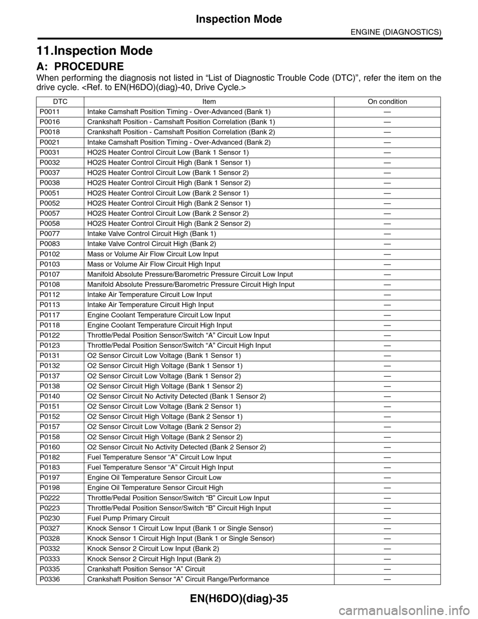
11.Inspection Mode
A: PROCEDURE
When performing the diagnosis not listed in “List of Diagnostic Trouble Code (DTC)”, refer the item on the
drive cycle.
DTC Item On condition
P0011 Intake Camshaft Position Timing - Over-Advanced (Bank 1) —
P0016 Crankshaft Position - Camshaft Position Correlation (Bank 1) —
P0018 Crankshaft Position - Camshaft Position Correlation (Bank 2) —
P0021 Intake Camshaft Position Timing - Over-Advanced (Bank 2) —
P0031 HO2S Heater Control Circuit Low (Bank 1 Sensor 1) —
P0032 HO2S Heater Control Circuit High (Bank 1 Sensor 1) —
P0037 HO2S Heater Control Circuit Low (Bank 1 Sensor 2) —
P0038 HO2S Heater Control Circuit High (Bank 1 Sensor 2) —
P0051 HO2S Heater Control Circuit Low (Bank 2 Sensor 1) —
P0052 HO2S Heater Control Circuit High (Bank 2 Sensor 1) —
P0057 HO2S Heater Control Circuit Low (Bank 2 Sensor 2) —
P0058 HO2S Heater Control Circuit High (Bank 2 Sensor 2) —
P0077 Intake Valve Control Circuit High (Bank 1) —
P0083 Intake Valve Control Circuit High (Bank 2) —
P0102 Mass or Volume Air Flow Circuit Low Input —
P0103 Mass or Volume Air Flow Circuit High Input —
P0107 Manifold Absolute Pressure/Barometric Pressure Circuit Low Input —
P0108 Manifold Absolute Pressure/Barometric Pressure Circuit High Input —
P0112 Intake Air Temperature Circuit Low Input —
P0113 Intake Air Temperature Circuit High Input —
P0117 Engine Coolant Temperature Circuit Low Input —
P0118 Engine Coolant Temperature Circuit High Input —
P0122 Throttle/Pedal Position Sensor/Switch “A” Circuit Low Input —
P0123 Throttle/Pedal Position Sensor/Switch “A” Circuit High Input —
P0131 O2 Sensor Circuit Low Voltage (Bank 1 Sensor 1) —
P0132 O2 Sensor Circuit High Voltage (Bank 1 Sensor 1) —
P0137 O2 Sensor Circuit Low Voltage (Bank 1 Sensor 2) —
P0138 O2 Sensor Circuit High Voltage (Bank 1 Sensor 2) —
P0140 O2 Sensor Circuit No Activity Detected (Bank 1 Sensor 2) —
P0151 O2 Sensor Circuit Low Voltage (Bank 2 Sensor 1) —
P0152 O2 Sensor Circuit High Voltage (Bank 2 Sensor 1) —
P0157 O2 Sensor Circuit Low Voltage (Bank 2 Sensor 2) —
P0158 O2 Sensor Circuit High Voltage (Bank 2 Sensor 2) —
P0160 O2 Sensor Circuit No Activity Detected (Bank 2 Sensor 2) —
P0182 Fuel Temperature Sensor “A” Circuit Low Input —
P0183 Fuel Temperature Sensor “A” Circuit High Input —
P0197 Engine Oil Temperature Sensor Circuit Low —
P0198 Engine Oil Temperature Sensor Circuit High —
P0222 Throttle/Pedal Position Sensor/Switch “B” Circuit Low Input —
P0223 Throttle/Pedal Position Sensor/Switch “B” Circuit High Input —
P0230 Fuel Pump Primary Circuit —
P0327 Knock Sensor 1 Circuit Low Input (Bank 1 or Single Sensor) —
P0328 Knock Sensor 1 Circuit High Input (Bank 1 or Single Sensor) —
P0332 Knock Sensor 2 Circuit Low Input (Bank 2) —
P0333 Knock Sensor 2 Circuit High Input (Bank 2) —
P0335 Crankshaft Position Sensor “A” Circuit —
P0336 Crankshaft Position Sensor “A” Circuit Range/Performance —
Page 1197 of 2453
EN(H6DO)(diag)-36
Inspection Mode
ENGINE (DIAGNOSTICS)
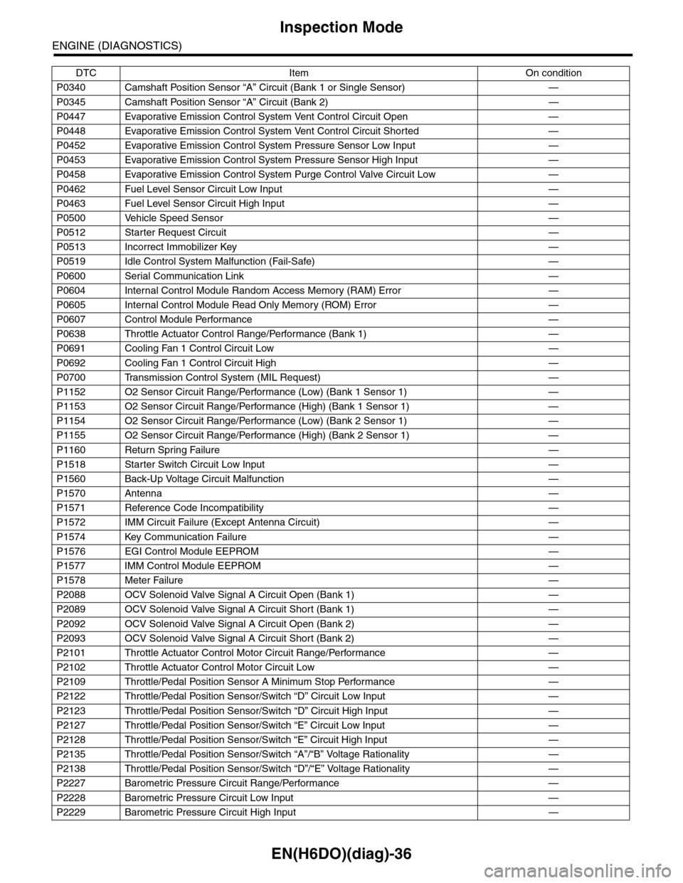
P0340 Camshaft Position Sensor “A” Circuit (Bank 1 or Single Sensor) —
P0345 Camshaft Position Sensor “A” Circuit (Bank 2) —
P0447 Evaporative Emission Control System Vent Control Circuit Open —
P0448 Evaporative Emission Control System Vent Control Circuit Shorted —
P0452 Evaporative Emission Control System Pressure Sensor Low Input —
P0453 Evaporative Emission Control System Pressure Sensor High Input —
P0458 Evaporative Emission Control System Purge Control Valve Circuit Low —
P0462 Fuel Level Sensor Circuit Low Input —
P0463 Fuel Level Sensor Circuit High Input —
P0500 Vehicle Speed Sensor—
P0512 Starter Request Circuit—
P0513 Incorrect Immobilizer Key —
P0519 Idle Control System Malfunction (Fail-Safe) —
P0600 Serial Communication Link —
P0604 Internal Control Module Random Access Memory (RAM) Error —
P0605 Internal Control Module Read Only Memory (ROM) Error —
P0607 Control Module Performance —
P0638 Throttle Actuator Control Range/Performance (Bank 1) —
P0691 Cooling Fan 1 Control Circuit Low —
P0692 Cooling Fan 1 Control Circuit High —
P0700 Transmission Control System (MIL Request) —
P1152 O2 Sensor Circuit Range/Performance (Low) (Bank 1 Sensor 1) —
P1153 O2 Sensor Circuit Range/Performance (High) (Bank 1 Sensor 1) —
P1154 O2 Sensor Circuit Range/Performance (Low) (Bank 2 Sensor 1) —
P1155 O2 Sensor Circuit Range/Performance (High) (Bank 2 Sensor 1) —
P1160 Return Spring Failure—
P1518 Starter Switch Circuit Low Input —
P1560 Back-Up Voltage Circuit Malfunction —
P1570 Antenna—
P1571 Reference Code Incompatibility —
P1572 IMM Circuit Failure (Except Antenna Circuit) —
P1574 Key Communication Failure —
P1576 EGI Control Module EEPROM —
P1577 IMM Control Module EEPROM —
P1578 Meter Failure—
P2088 OCV Solenoid Valve Signal A Circuit Open (Bank 1) —
P2089 OCV Solenoid Valve Signal A Circuit Short (Bank 1) —
P2092 OCV Solenoid Valve Signal A Circuit Open (Bank 2) —
P2093 OCV Solenoid Valve Signal A Circuit Short (Bank 2) —
P2101 Throttle Actuator Control Motor Circuit Range/Performance —
P2102 Throttle Actuator Control Motor Circuit Low —
P2109 Throttle/Pedal Position Sensor A Minimum Stop Performance —
P2122 Throttle/Pedal Position Sensor/Switch “D” Circuit Low Input —
P2123 Throttle/Pedal Position Sensor/Switch “D” Circuit High Input —
P2127 Throttle/Pedal Position Sensor/Switch “E” Circuit Low Input —
P2128 Throttle/Pedal Position Sensor/Switch “E” Circuit High Input —
P2135 Throttle/Pedal Position Sensor/Switch “A”/“B” Voltage Rationality —
P2138 Throttle/Pedal Position Sensor/Switch “D”/“E” Voltage Rationality —
P2227 Barometric Pressure Circuit Range/Performance —
P2228 Barometric Pressure Circuit Low Input —
P2229 Barometric Pressure Circuit High Input —
DTC Item On condition
Page 1202 of 2453
EN(H6DO)(diag)-41
Drive Cycle
ENGINE (DIAGNOSTICS)
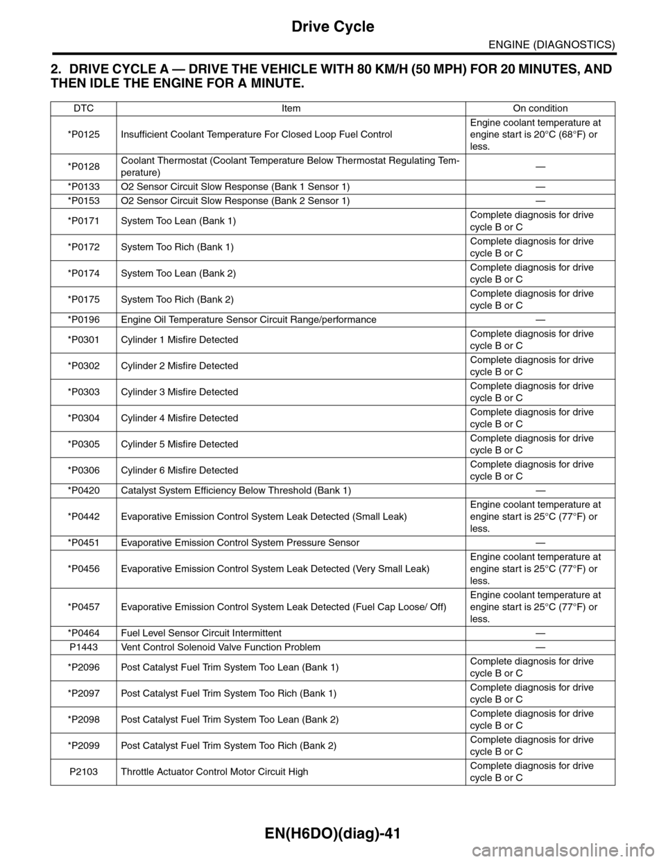
2. DRIVE CYCLE A — DRIVE THE VEHICLE WITH 80 KM/H (50 MPH) FOR 20 MINUTES, AND
THEN IDLE THE ENGINE FOR A MINUTE.
DTC Item On condition
*P0125 Insufficient Coolant Temperature For Closed Loop Fuel Control
Engine coolant temperature at
engine start is 20°C (68°F) or
less.
*P0128Coolant Thermostat (Coolant Temperature Below Thermostat Regulating Tem-
perature)—
*P0133 O2 Sensor Circuit Slow Response (Bank 1 Sensor 1) —
*P0153 O2 Sensor Circuit Slow Response (Bank 2 Sensor 1) —
*P0171 System Too Lean (Bank 1)Complete diagnosis for drive
cycle B or C
*P0172 System Too Rich (Bank 1)Complete diagnosis for drive
cycle B or C
*P0174 System Too Lean (Bank 2)Complete diagnosis for drive
cycle B or C
*P0175 System Too Rich (Bank 2)Complete diagnosis for drive
cycle B or C
*P0196 Engine Oil Temperature Sensor Circuit Range/performance —
*P0301 Cylinder 1 Misfire DetectedComplete diagnosis for drive
cycle B or C
*P0302 Cylinder 2 Misfire DetectedComplete diagnosis for drive
cycle B or C
*P0303 Cylinder 3 Misfire DetectedComplete diagnosis for drive
cycle B or C
*P0304 Cylinder 4 Misfire DetectedComplete diagnosis for drive
cycle B or C
*P0305 Cylinder 5 Misfire DetectedComplete diagnosis for drive
cycle B or C
*P0306 Cylinder 6 Misfire DetectedComplete diagnosis for drive
cycle B or C
*P0420 Catalyst System Efficiency Below Threshold (Bank 1) —
*P0442 Evaporative Emission Control System Leak Detected (Small Leak)
Engine coolant temperature at
engine start is 25°C (77°F) or
less.
*P0451 Evaporative Emission Control System Pressure Sensor —
*P0456 Evaporative Emission Control System Leak Detected (Very Small Leak)
Engine coolant temperature at
engine start is 25°C (77°F) or
less.
*P0457 Evaporative Emission Control System Leak Detected (Fuel Cap Loose/ Off)
Engine coolant temperature at
engine start is 25°C (77°F) or
less.
*P0464 Fuel Level Sensor Circuit Intermittent —
P1443 Vent Control Solenoid Valve Function Problem —
*P2096 Post Catalyst Fuel Trim System Too Lean (Bank 1)Complete diagnosis for drive
cycle B or C
*P2097 Post Catalyst Fuel Trim System Too Rich (Bank 1)Complete diagnosis for drive
cycle B or C
*P2098 Post Catalyst Fuel Trim System Too Lean (Bank 2)Complete diagnosis for drive
cycle B or C
*P2099 Post Catalyst Fuel Trim System Too Rich (Bank 2)Complete diagnosis for drive
cycle B or C
P2103 Throttle Actuator Control Motor Circuit HighComplete diagnosis for drive
cycle B or C
Page 1208 of 2453
![SUBARU TRIBECA 2009 1.G Service Workshop Manual EN(H6DO)(diag)-47
Compulsory Valve Operation Check Mode
ENGINE (DIAGNOSTICS)
13) Pressing the [NO] key completes the compul-
sory valve operation check mode. The display will
then return to SUBARU TRIBECA 2009 1.G Service Workshop Manual EN(H6DO)(diag)-47
Compulsory Valve Operation Check Mode
ENGINE (DIAGNOSTICS)
13) Pressing the [NO] key completes the compul-
sory valve operation check mode. The display will
then return to](/manual-img/17/7322/w960_7322-1207.png)
EN(H6DO)(diag)-47
Compulsory Valve Operation Check Mode
ENGINE (DIAGNOSTICS)
13) Pressing the [NO] key completes the compul-
sory valve operation check mode. The display will
then return to the «Actuator ON/OFF Operation»
screen.
•A list of the support data is shown in the following
table.
NOTE:
•The following parts will be displayed but not
functional.
•For detailed operation procedure, refer to the
“SUBARU SELECT MONITOR OPERATION
MANUAL”.
Description Display
Compulsory fuel pump relay oper-
ation checkFuel Pump
Compulsory radiator fan relay
operation checkRadiator Fan Relay
Compulsory air conditioning relay
operation checkA/C Compressor Relay
Compulsory purge control sole-
noid valve operation checkCPC Solenoid
Compulsory drain valve operation
checkVe n t C o n t r o l S o l e n o i d
Display
EGR Solenoid
ASV Solenoid
FICD Solenoid
Pressure Switching Solenoid 1
Pressure Switching Solenoid 2
Wa st e g at e Con t r ol S ol e no i d
AAI Solenoid
Exhaust Bypass Valve Control Permit Flag
PCV Solenoid
Fuel tank sensor control valve
Page 1225 of 2453
EN(H6DO)(diag)-64
Diagnostics for Engine Starting Failure
ENGINE (DIAGNOSTICS)
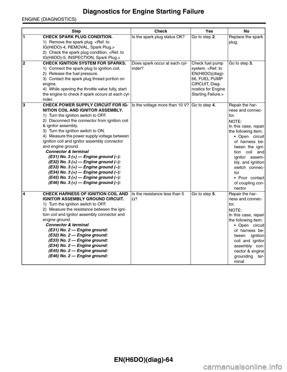
Step Check Yes No
1CHECK SPARK PLUG CONDITION.
1) Remove the spark plug.
2) Check the spark plug condition.
Is the spark plug status OK? Go to step 2.Replace the spark
plug.
2CHECK IGNITION SYSTEM FOR SPARKS.
1) Connect the spark plug to ignition coil.
2) Release the fuel pressure.
3) Contact the spark plug thread portion on
engine.
4) While opening the throttle valve fully, start
the engine to check if spark occurs at each cyl-
inder.
Does spark occur at each cyl-
inder?
Check fuel pump
system.
66, FUEL PUMP
CIRCUIT, Diag-
nostics for Engine
Starting Failure.>
Go to step 3.
3CHECK POWER SUPPLY CIRCUIT FOR IG-
NITION COIL AND IGNITOR ASSEMBLY.
1) Turn the ignition switch to OFF.
2) Disconnect the connector from ignition coil
& ignitor assembly.
3) Turn the ignition switch to ON.
4) Measure the power supply voltage between
ignition coil and ignitor assembly connector
and engine ground.
Connector & terminal
(E31) No. 3 (+) — Engine ground (–):
(E32) No. 3 (+) — Engine ground (–):
(E33) No. 3 (+) — Engine ground (–):
(E34) No. 3 (+) — Engine ground (–):
(E45) No. 3 (+) — Engine ground (–):
(E46) No. 3 (+) — Engine ground (–):
Is the voltage more than 10 V? Go to step 4.Repair the har-
ness and connec-
tor.
NOTE:
In this case, repair
the following item:
•Open circuit
of harness be-
tween the igni-
tion coil and
ignitor assem-
bly, and ignition
switch connec-
tor
•Poor contact
of coupling con-
nector
4CHECK HARNESS OF IGNITION COIL AND
IGNITOR ASSEMBLY GROUND CIRCUIT.
1) Turn the ignition switch to OFF.
2) Measure the resistance between the igni-
tion coil and ignitor assembly connector and
engine ground.
Connector & terminal
(E31) No. 2 — Engine ground:
(E32) No. 2 — Engine ground:
(E33) No. 2 — Engine ground:
(E34) No. 2 — Engine ground:
(E45) No. 2 — Engine ground:
(E46) No. 2 — Engine ground:
Is the resistance less than 5
Ω?
Go to step 5.Repair the har-
ness and connec-
tor.
NOTE:
In this case, repair
the following item:
•Open circuit
of harness be-
tween ignition
coil and ignitor
assembly con-
nector & engine
grounding ter-
minal
Page 1228 of 2453
EN(H6DO)(diag)-67
Diagnostics for Engine Starting Failure
ENGINE (DIAGNOSTICS)
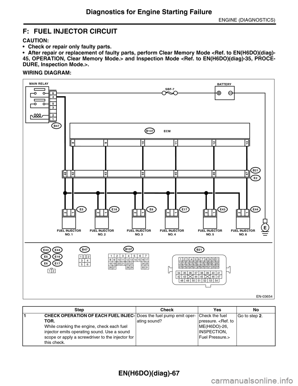
F: FUEL INJECTOR CIRCUIT
CAUTION:
•Check or repair only faulty parts.
•After repair or replacement of faulty parts, perform Clear Memory Mode
WIRING DIAGRAM:
EN-03654
E6E17
E5E16
E43E44
12121212
109811
4248434445
ECMB137
E5E16E6E17
B21
E2
FUEL INJECTORNO. 1FUEL INJECTORNO. 2FUEL INJECTORNO. 3FUEL INJECTORNO. 4
BATTERY
1212
1213
4647
E43E44
FUEL INJECTORNO. 5FUEL INJECTORNO. 6
SBF-7
B47
MAIN RELAY
12
35
46
B47
3412
56
12
B21
123412131415567816171819910 1120212223 24 25 2627 28 29 3031 32 33
3534 37363938 41404342 4445 47464948 51505352 54
E
B137
85610 11 12 13 14 157213416
3019 20 2228 29
91718 2521 23 243126 27
Step Check Yes No
1CHECK OPERATION OF EACH FUEL INJEC-
TOR.
While cranking the engine, check each fuel
injector emits operating sound. Use a sound
scope or apply a screwdriver to the injector for
this check.
Does the fuel pump emit oper-
ating sound?
Check the fuel
pressure.
INSPECTION,
Fuel Pressure.>
Go to step 2.
Page 1231 of 2453
EN(H6DO)(diag)-70
List of Diagnostic Trouble Code (DTC)
ENGINE (DIAGNOSTICS)
P0077 Intake Valve Control Circuit High
(Bank 1)
(DTC).>
P0082 Intake Valve Control Circuit Low
(Bank 2)
(DTC).>
P0083 Intake Valve Control Circuit High
(Bank 2)
(DTC).>
P0101 Mass or Volume Air Flow Circuit
Range/Performance
Tr o u b l e C o d e ( D T C ) . >
P0102 Mass or Volume Air Flow Circuit Low
Input
(DTC).>
P0103 Mass or Volume Air Flow Circuit High
Input
(DTC).>
P0107 Manifold Absolute Pressure/Baro-
metric Pressure Circuit Low Input
cedure with Diagnostic Trouble Code (DTC).>
P0108 Manifold Absolute Pressure/Baro-
metric Pressure Circuit High Input
cedure with Diagnostic Trouble Code (DTC).>
P0111 Intake Air Temperature Circuit
Range/Performance
Tr o u b l e C o d e ( D T C ) . >
P0112 Intake Air Temperature Circuit Low
Input
(DTC).>
P0113 Intake Air Temperature Circuit High
Input
(DTC).>
P0117 Engine Coolant Temperature Circuit
Low Input
Code (DTC).>
P0118 Engine Coolant Temperature Circuit
High Input
Code (DTC).>
P0122 Throttle/Pedal Position Sensor/
Switch “A” Circuit Low Input
Diagnostic Trouble Code (DTC).>
P0123 Throttle/Pedal Position Sensor/
Switch “A” Circuit High Input
Diagnostic Trouble Code (DTC).>
P0125 Insufficient Coolant Temperature For
Closed Loop Fuel Control
dure with Diagnostic Trouble Code (DTC).>
P0126 Insufficient Coolant Temperature for
Stable Operation
Diagnostic Trouble Code (DTC).>
P0128 Coolant Thermostat (Coolant Tem-
perature Below Thermostat Regulat-
ing Temperature)
PERATURE), Diagnostic Procedure with Diagnostic Trouble Code (DTC).>
P0131 O2 Sensor Circuit Low Voltage (Bank
1 Sensor 1)
ble Code (DTC).>
DTC Item Reference