Page 2244 of 2453
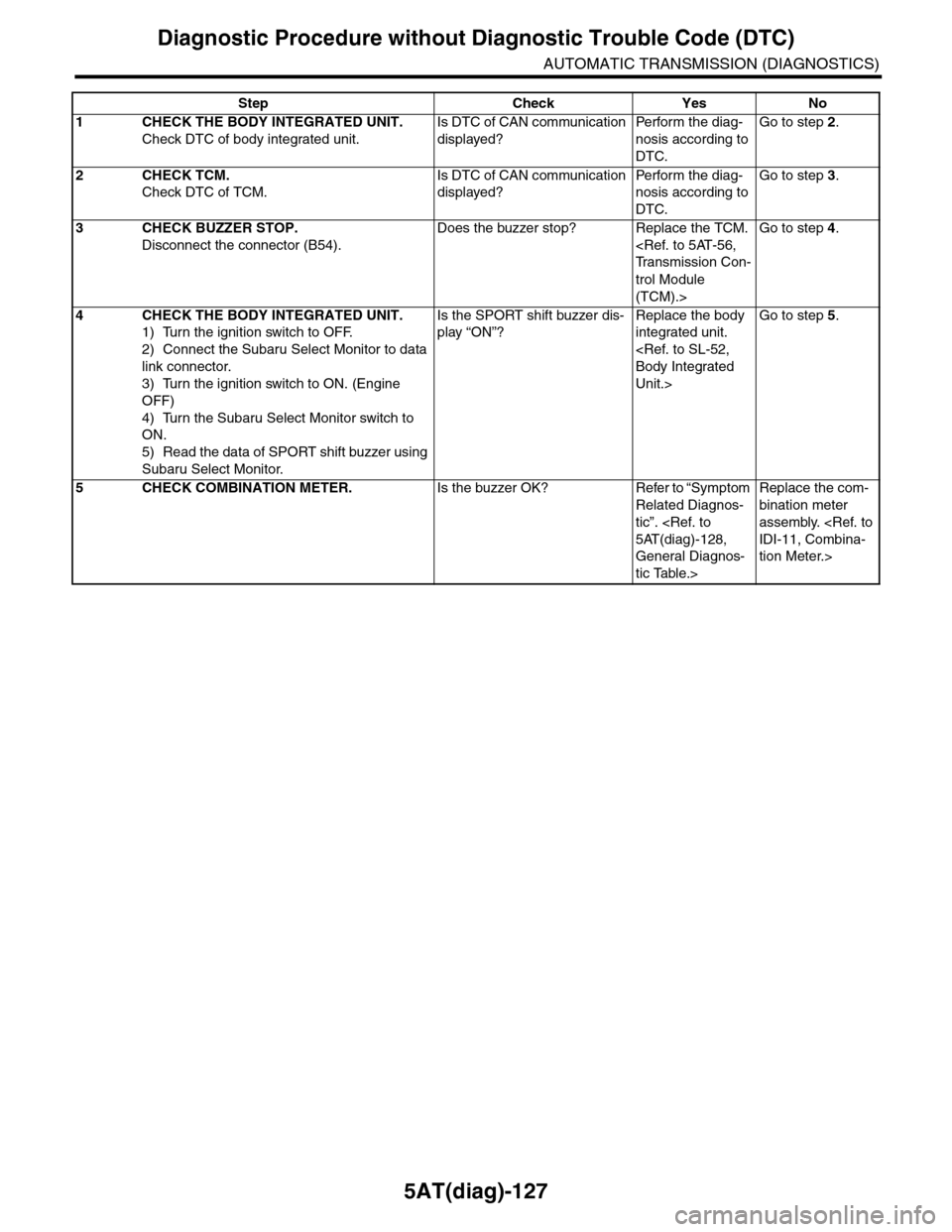
5AT(diag)-127
Diagnostic Procedure without Diagnostic Trouble Code (DTC)
AUTOMATIC TRANSMISSION (DIAGNOSTICS)
Step Check Yes No
1CHECK THE BODY INTEGRATED UNIT.
Check DTC of body integrated unit.
Is DTC of CAN communication
displayed?
Pe r for m t h e d ia g -
nosis according to
DTC.
Go to step 2.
2CHECK TCM.
Check DTC of TCM.
Is DTC of CAN communication
displayed?
Pe r for m t h e d ia g -
nosis according to
DTC.
Go to step 3.
3CHECK BUZZER STOP.
Disconnect the connector (B54).
Does the buzzer stop? Replace the TCM.
Tr a n s m i s s i o n C o n -
trol Module
(TCM).>
Go to step 4.
4CHECK THE BODY INTEGRATED UNIT.
1) Turn the ignition switch to OFF.
2) Connect the Subaru Select Monitor to data
link connector.
3) Turn the ignition switch to ON. (Engine
OFF)
4) Turn the Subaru Select Monitor switch to
ON.
5) Read the data of SPORT shift buzzer using
Subaru Select Monitor.
Is the SPORT shift buzzer dis-
play “ON”?
Replace the body
integrated unit.
Body Integrated
Unit.>
Go to step 5.
5CHECK COMBINATION METER.Is the buzzer OK? Refer to “Symptom
Related Diagnos-
tic”.
5AT(diag)-128,
General Diagnos-
tic Table.>
Replace the com-
bination meter
assembly.
IDI-11, Combina-
tion Meter.>
Page 2259 of 2453
CS-7
AT Shift Lock Control System
CONTROL SYSTEMS
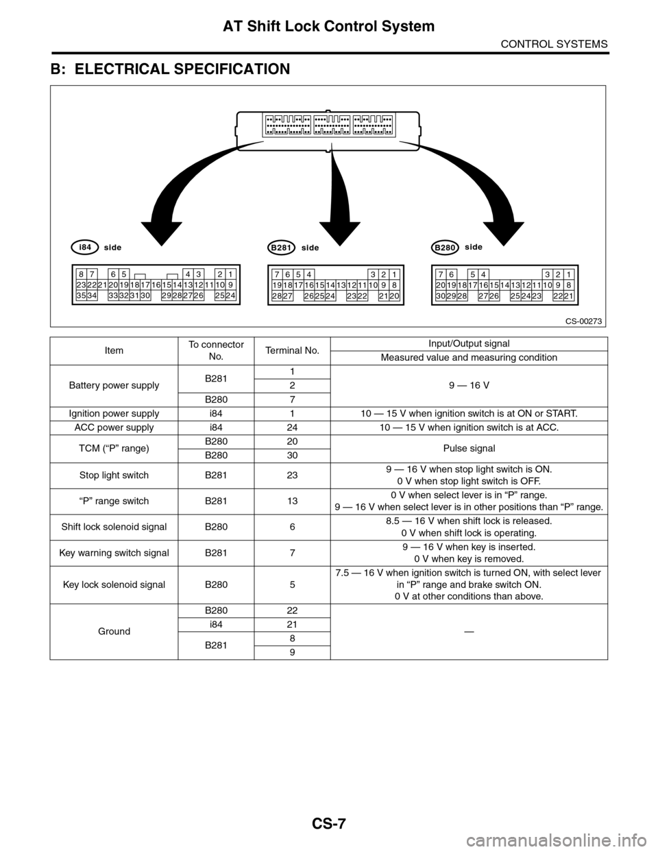
B: ELECTRICAL SPECIFICATION
ItemTo c o n n e c t o r
No.Te r m i n a l N o .Input/Output signal
Measured value and measuring condition
Battery power supplyB2811
9 — 16 V2
B280 7
Ignition power supply i84 1 10 — 15 V when ignition switch is at ON or START.
ACC power supply i84 24 10 — 15 V when ignition switch is at ACC.
TCM (“P” range)B280 20Pulse signalB280 30
Stop light switch B281 239 — 16 V when stop light switch is ON.
0 V when stop light switch is OFF.
“P” range switch B281 130 V when select lever is in “P” range.
9 — 16 V when select lever is in other positions than “P” range.
Shift lock solenoid signal B280 68.5 — 16 V when shift lock is released.
0 V when shift lock is operating.
Key war ning switch signal B281 79 — 16 V when key is inserted.
0 V when key is removed.
Key lock solenoid signal B280 5
7.5 — 16 V when ignition switch is turned ON, with select lever
in “P” range and brake switch ON.
0 V at other conditions than above.
Ground
B280 22
—i84 21
B2818
9
CS-00273
71928
61827
51741626152514241312231122
3102921
1820
B281side
72030
619291828
51741627152614132512241123
3102922
1821
B280side
82335
722342162033
51932183117301615291428
41327
312261121025
1924
i84side
Page 2260 of 2453
CS-8
AT Shift Lock Control System
CONTROL SYSTEMS
C: WIRING DIAGRAM
(1) Ignition switch (4) Body integrated unit (7) Shift lock solenoid
(2) Stop light switch (5) TCM (“P” range) (8) “P” range switch
(3) Key warning switch (6) Key lock solenoid (9) Battery
CS-00363
OFFACCON
(1)
(2)
(3)
(4)
(9)
(6)
(7)
(8)
(5)
Page 2261 of 2453
CS-9
AT Shift Lock Control System
CONTROL SYSTEMS
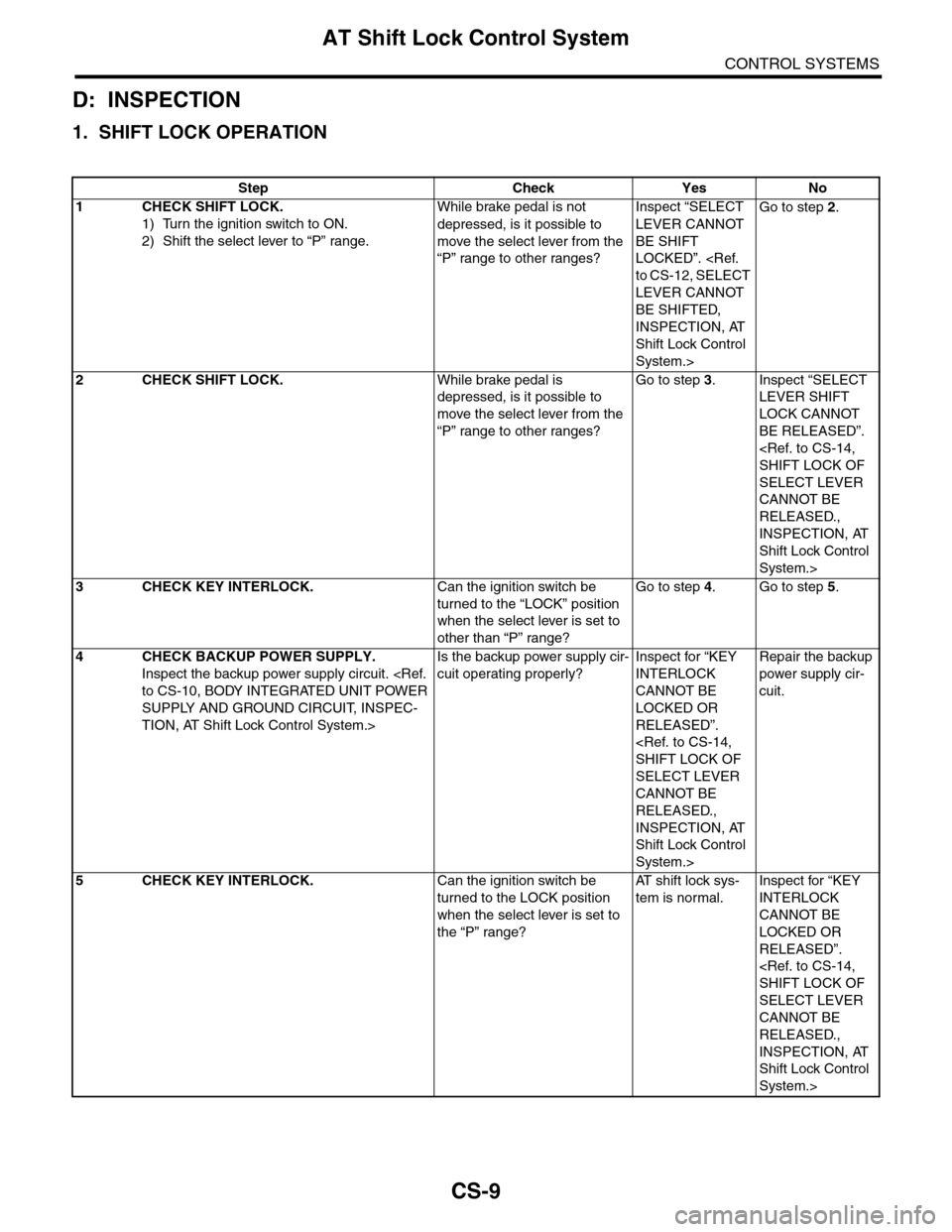
D: INSPECTION
1. SHIFT LOCK OPERATION
Step Check Yes No
1CHECK SHIFT LOCK.
1) Turn the ignition switch to ON.
2) Shift the select lever to “P” range.
While brake pedal is not
depressed, is it possible to
move the select lever from the
“P” range to other ranges?
Inspect “SELECT
LEVER CANNOT
BE SHIFT
LOCKED”.
to CS-12, SELECT
LEVER CANNOT
BE SHIFTED,
INSPECTION, AT
Shift Lock Control
System.>
Go to step 2.
2CHECK SHIFT LOCK.While brake pedal is
depressed, is it possible to
move the select lever from the
“P” range to other ranges?
Go to step 3.Inspect “SELECT
LEVER SHIFT
LOCK CANNOT
BE RELEASED”.
SHIFT LOCK OF
SELECT LEVER
CANNOT BE
RELEASED.,
INSPECTION, AT
Shift Lock Control
System.>
3CHECK KEY INTERLOCK.Can the ignition switch be
turned to the “LOCK” position
when the select lever is set to
other than “P” range?
Go to step 4.Go to step 5.
4CHECK BACKUP POWER SUPPLY.
Inspect the backup power supply circuit.
to CS-10, BODY INTEGRATED UNIT POWER
SUPPLY AND GROUND CIRCUIT, INSPEC-
TION, AT Shift Lock Control System.>
Is the backup power supply cir-
cuit operating properly?
Inspect for “KEY
INTERLOCK
CANNOT BE
LOCKED OR
RELEASED”.
SHIFT LOCK OF
SELECT LEVER
CANNOT BE
RELEASED.,
INSPECTION, AT
Shift Lock Control
System.>
Repair the backup
power supply cir-
cuit.
5CHECK KEY INTERLOCK.Can the ignition switch be
turned to the LOCK position
when the select lever is set to
the “P” range?
AT s h i f t l o c k s y s -
tem is normal.
Inspect for “KEY
INTERLOCK
CANNOT BE
LOCKED OR
RELEASED”.
SHIFT LOCK OF
SELECT LEVER
CANNOT BE
RELEASED.,
INSPECTION, AT
Shift Lock Control
System.>
Page 2262 of 2453
CS-10
AT Shift Lock Control System
CONTROL SYSTEMS
2. BODY INTEGRATED UNIT POWER SUPPLY AND GROUND CIRCUIT
CS-00599
OFF ACC
ACC
ON
B
IG
MAIN SBF
SBF-8
NO.12
B281C:
B280B:
A1C2C8C9
E
NO.7
B7
NO.8
A21
E
SBF-6
i84A:
NO.31
A24B22
IGNITIONSWITCH
BODY INTEGRATED UNIT
BATTERY
567821943102422 23 25111213141526 27281617181920 21
5467821931022 231112131415242526 2716171828 29192021 30
1234567891011121314151617181920212223242526272829303132333435
B281C:B280B:i84A:
Page 2263 of 2453
CS-11
AT Shift Lock Control System
CONTROL SYSTEMS
Step Check Yes No
1CHECK DTC OF BODY INTEGRATED UNIT.
Check DTC of the body integrated unit.
Diagnostic Trouble Code (DTC).>
Is the DTC of power line dis-
played on body integrated
unit?
Repair or replace it
according to the
DTC.
Go to step 2.
2CHECK HARNESS CONNECTOR BETWEEN
BODY INTEGRATED UNIT AND CHASSIS
GROUND.
1) Turn the ignition switch to OFF.
2) Measure the harness resistance between
the body integrated unit and chassis ground.
Connector & terminal
(i84) No. 21 — Chassis ground:
(B280) No. 22 — Chassis ground:
(B281) No. 8 — Chassis ground:
(B281) No. 9 — Chassis ground:
Is the resistance less than 1
Ω?
Go to step 3.Repair the open
circuit of harness
between the body
integrated unit and
chassis ground.
3CHECK POOR CONTACT.Is there poor contact in con-
nector?
Repair the poor
contact.
Check the body
integrated unit.
Page 2265 of 2453
CS-13
AT Shift Lock Control System
CONTROL SYSTEMS
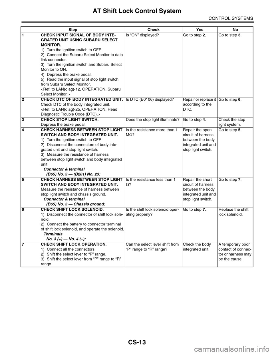
Step Check Yes No
1CHECK INPUT SIGNAL OF BODY INTE-
GRATED UNIT USING SUBARU SELECT
MONITOR.
1) Turn the ignition switch to OFF.
2) Connect the Subaru Select Monitor to data
link connector.
3) Turn the ignition switch and Subaru Select
Monitor to ON.
4) Depress the brake pedal.
5) Read the input signal of stop light switch
from Subaru Select Monitor.
Select Monitor.>
Is “ON” displayed? Go to step 2.Go to step 3.
2CHECK DTC OF BODY INTEGRATED UNIT.
Check DTC of the body integrated unit.
Diagnostic Trouble Code (DTC).>
Is DTC (B0106) displayed? Repair or replace it
according to the
DTC.
Go to step 6.
3CHECK STOP LIGHT SWITCH.
Depress the brake pedal.
Does the stop light illuminate? Go to step 4.Check the stop
light system.
4CHECK HARNESS BETWEEN STOP LIGHT
SWITCH AND BODY INTEGRATED UNIT.
1) Turn the ignition switch to OFF.
2) Disconnect the connectors of body inte-
grated unit and stop light switch.
3) Measure the resistance of harness
between stop light switch and body integrated
unit.
Connector & terminal
(B65) No. 3 — (B281) No. 23:
Is the resistance more than 1
MΩ?
Repair the open
circuit of harness
between the body
integrated unit and
stop light switch.
Go to step 5.
5CHECK HARNESS BETWEEN STOP LIGHT
SWITCH AND BODY INTEGRATED UNIT.
Measure the resistance of harness between
stop light switch and chassis ground.
Connector & terminal
(B65) No. 3 — Chassis ground:
Is the resistance less than 1
Ω?
Repair the short
circuit of harness
between the body
integrated unit and
stop light switch.
Go to step 7.
6CHECK SHIFT LOCK SOLENOID.
1) Disconnect the connector of shift lock sole-
noid.
2) Connect the battery to connector terminal
of shift lock solenoid, and operate the solenoid.
Te r m i n a l s
No. 3 (+) — No. 4 (–):
Is the shift lock solenoid oper-
ating properly?
Go to step 7.Replace the shift
lock solenoid.
7CHECK SHIFT LOCK OPERATION.
1) Connect all the connectors.
2) Shift the select lever to “P” range.
3) Shift the select lever from “P” range to “R”
range.
Can the select lever shift from
“P” range to “R” range?
Check the body
integrated unit.
A temporary poor
contact of connec-
tor or harness may
be the cause.
Page 2267 of 2453
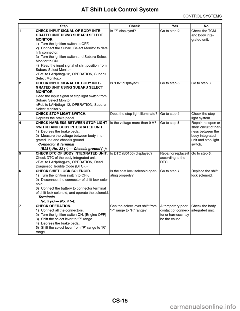
CS-15
AT Shift Lock Control System
CONTROL SYSTEMS
Step Check Yes No
1CHECK INPUT SIGNAL OF BODY INTE-
GRATED UNIT USING SUBARU SELECT
MONITOR.
1) Turn the ignition switch to OFF.
2) Connect the Subaru Select Monitor to data
link connector.
3) Turn the ignition switch and Subaru Select
Monitor to ON.
4) Read the input signal of shift position from
Subaru Select Monitor.
Select Monitor.>
Is “7” displayed? Go to step 2.Check the TCM
and body inte-
grated unit.
2CHECK INPUT SIGNAL OF BODY INTE-
GRATED UNIT USING SUBARU SELECT
MONITOR.
Read the input signal of stop light switch from
Subaru Select Monitor.
Select Monitor.>
Is “ON” displayed? Go to step 5.Go to step 3.
3CHECK STOP LIGHT SWITCH.
Depress the brake pedal.
Does the stop light illuminate? Go to step 4.Check the stop
light system.
4CHECK HARNESS BETWEEN STOP LIGHT
SWITCH AND BODY INTEGRATED UNIT.
1) Depress the brake pedal.
2) Measure the voltage between body inte-
grated unit and chassis ground.
Connector & terminal
(B281) No. 23 (+) — Chassis ground (–):
Is the voltage more than 9 V? Go to step 5.Repair the open or
short circuit of har-
ness between the
body integrated
unit and stop light
switch.
5CHECK DTC OF BODY INTEGRATED UNIT.
Check DTC of the body integrated unit.
Diagnostic Trouble Code (DTC).>
Is DTC (B0106) displayed? Repair or replace it
according to the
DTC.
Go to step 6.
6CHECK SHIFT LOCK SOLENOID.
1) Turn the ignition switch to OFF.
2) Disconnect the connector of shift lock sole-
noid.
3) Connect the battery to connector terminal
of shift lock solenoid, and operate the solenoid.
Te r m i n a l s
No. 3 (+) — No. 4 (–):
Is the shift lock solenoid oper-
ating properly?
Go to step 7.Replace the shift
lock solenoid.
7CHECK OPERATION.
1) Connect all the connectors.
2) Turn the ignition switch ON. (Engine OFF)
3) Shift the select lever to “P” range.
4) Depress the brake pedal.
5) Shift the select lever from “P” range to “R”
range.
Can the select lever shift from
“P” range to “R” range?
A temporary poor
contact of connec-
tor or harness may
be the cause.
Check the body
integrated unit.