2009 SUBARU TRIBECA parking brake
[x] Cancel search: parking brakePage 2047 of 2453
5AT-31
Time Lag Test
AUTOMATIC TRANSMISSION
6. Time Lag Test
A: INSPECTION
NOTE:
When the select lever is shifted while the engine is
idling, there will be a certain time elapse or lag be-
fore shock is felt. Using this, check the condition of
forward brake, reverse brake, 1st one-way clutch,
forward one-way clutch and 3rd one-way clutch.
•Perform the test at normal operation fluid tem-
perature of 70 — 80°C (158 — 176°F).
•Be sure to allow a one minute interval between
tests.
•Make three measurements and take the average
value.
1) Fully apply the parking brake.
2) Start the engine.
Check the idle speed (A/C OFF).
3) Shift the select lever from “N” to “D” range. Using
a stop watch, measure the time-lag from shifting
the lever until the shock is felt.
Time-lag
Specification: 1.2 sec. or less
If “N” → “D” time-lag is longer than specification:
•Line pressure too low
•Forward brake worn
•One–way clutch not operating properly
4) In the same manner, measure the time lag of “N”
→ “R”.
Time-lag
Specification: 1.5 sec. or less
If “N” → “R” time lag is longer than specification:
•Line pressure too low
•Reverse brake worn
Page 2298 of 2453
WI-14
Working Precautions
WIRING SYSTEM
2. Working Precautions
A: PRECAUTIONS WHEN WORKING
WITH THE PARTS MOUNTED ON
THE VEHICLE
1) When working under a vehicle which is jacked-
up, always be sure to use rigid rack.
2) The parking brake must always be applied dur-
ing working. Also, in automatic transmission vehi-
cles, keep the select lever set to the P (Parking)
range.
3) Be sure the workshop is properly ventilated
when running the engine. Further, be careful not to
touch the belt or fan while the engine is operating.
4) Be careful not to touch hot metal parts, especial-
ly the radiator and exhaust system immediately af-
ter the engine has been turned off.
B: PRECAUTIONS IN TROUBLE DI-
AGNOSIS AND REPAIR OF ELEC-
TRIC PARTS
1) The battery cable must be disconnected from
the battery’s (–) terminal, and the ignition switch
must be set to the OFF position, unless otherwise
required by the diagnostics.
2) Securely fasten the wiring harness with clamps
and slips so that the harness does not interfere with
the body end parts or edges and bolts or screws.
3) When installing parts, be careful not to catch
them on the wiring harness.
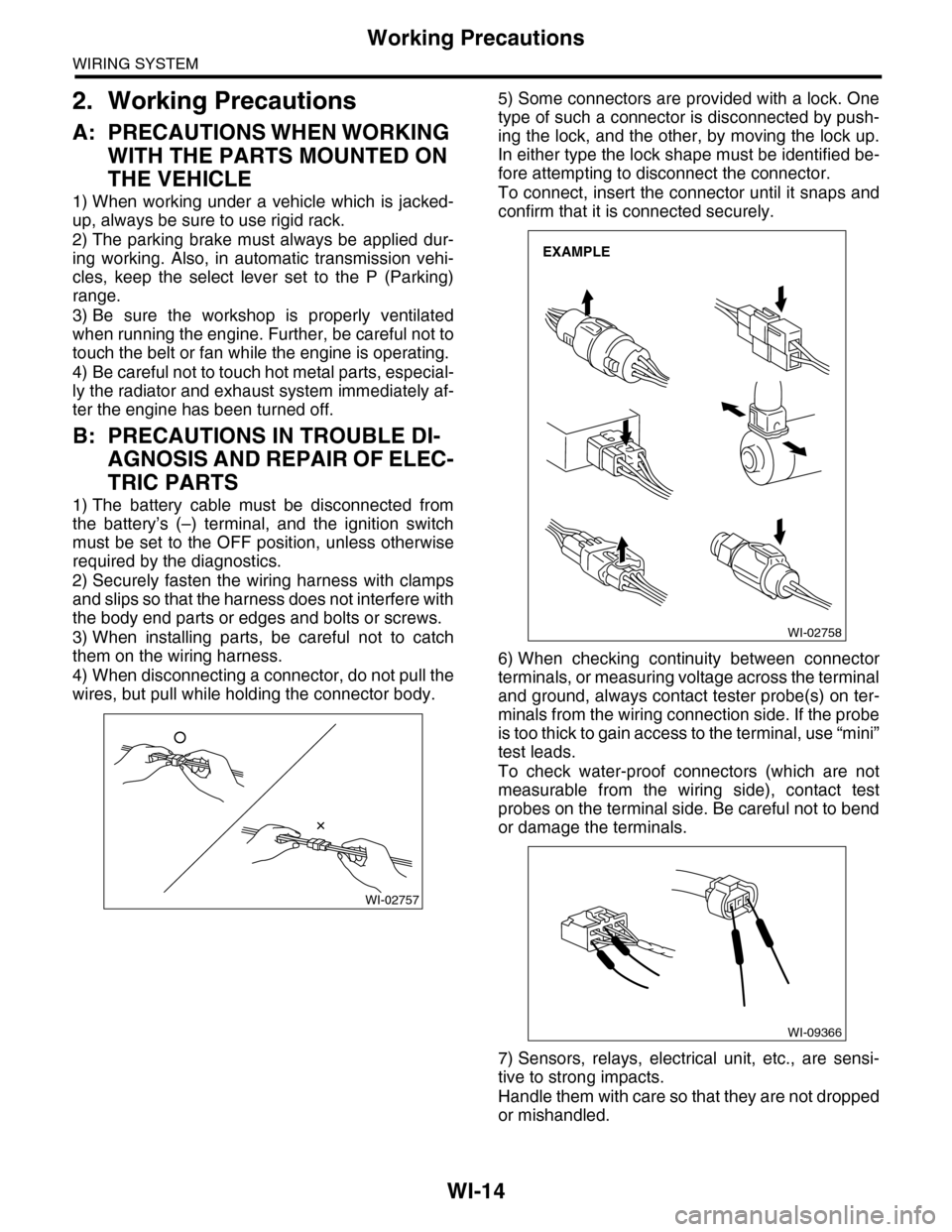
4) When disconnecting a connector, do not pull the
wires, but pull while holding the connector body.
5) Some connectors are provided with a lock. One
type of such a connector is disconnected by push-
ing the lock, and the other, by moving the lock up.
In either type the lock shape must be identified be-
fore attempting to disconnect the connector.
To connect, insert the connector until it snaps and
confirm that it is connected securely.
6) When checking continuity between connector
terminals, or measuring voltage across the terminal
and ground, always contact tester probe(s) on ter-
minals from the wiring connection side. If the probe
is too thick to gain access to the terminal, use “mini”
test leads.
To check water-proof connectors (which are not
measurable from the wiring side), contact test
probes on the terminal side. Be careful not to bend
or damage the terminals.
7) Sensors, relays, electrical unit, etc., are sensi-
tive to strong impacts.
Handle them with care so that they are not dropped
or mishandled.
WI-02757
WI-02758
EXAMPLE
WI-09366
Page 2345 of 2453
WI-61
Vehicle Dynamics Control System
WIRING SYSTEM
WI-08067
VDC-02VDC-02
VDCWARNINGLIGHT/TCS OFFINDICATORLIGHT
A16
BY
A15
BYPV
BY
COMBINATIONMETER
MICRO COMPUTER
CAN TRANSCEIVER& RECEIVER
FB-36F/B FUSE NO. 5(IG)
TO POWER SUPPLY CIRCUIT
I/F
i10A:
i11B:
GW
16
YL
33
LgR
3
PARKING BRAKE/BRAKE FLUID LEVELWARNING LIGHTABS WARNING
LIGHT
B8
17
LgB
18
LgR
GWLgR
B6
LgRLgB
i3
B38
REVERSECIRCUITREVERSECIRCUIT
VDC CONTROL MODULE
B310
OPCONNECTORB228
YL5
VDCOPERATIONINDICATORLIGHT
B228
131415
123456789101112
DRIVER
REF. TO GROUNDCIRCUIT [GND-05]
A29A30
REF. TO ENGINEELECTRICAL SYSTEM[E/G-03]
REF. TO CANCOMMUNICATIONSYSTEM [CAN-01]
B38
1234 567891011 1213 14 15 16 17 18 19 20123456789101112
i126(BLACK) (GREEN)(GREEN)
i127(BLACK)
(BLACK)
BrW
A3A4
BrWBrW
BrW
JOINT CONNECTOR
i126i127
1*
2*2*
: TERMINAL NO. OPTIONAL ARRANGEMENT AMONG 7, 8 AND 9
2*
: TERMINAL NO. OPTIONAL ARRANGEMENT AMONG 10, 11 AND 12
1*
B310
i10
19 20 2115 16 17 182223242526272829301234568910 11 12 13 147
A:
1234
1516171819202122232425262728293031323334353637383940414245464344568910 11 12 13 147
i11
123 45678910 11 12 13 14
B:
Page 2372 of 2453
WI-88
Headlight System
WIRING SYSTEM
WI-08094
H/L-03H/L-03
DAYTIME RUNNING LIGHTCONTROL MODULE
DIODE(PARKING BRAKE)
DIMMER &PA S S I N GSWITCH
LIGHTINGSWITCH
PA R K I N GBRAKESWITCH
B405
H/L-02D
H/L-02C
H/L-02B
817
B4
16
Gr
Gr
B71
23456718910 11 12 13 14 15 16 17
A10
B
B404
B71
B71
PGr34
B
B
7
LWOrWRW
13
OrW
REF. TO GROUNDCIRCUIT [GND-02]
B
REF. TO GROUNDCIRCUIT [GND-02]
UP
HU HF HL E
LOW
PASS
OFF
1
2
HC TC EC
B405F26
123
B96B:
B242A:
B242A:
12346789510
14723568
B96B:(BLACK)(BROWN)(GREEN)
REF. TO PARKING BRAKE &BRAKE FLUID LEVELWARNING LIGHT SYSTEM[BRW-01]
1234
Page 2397 of 2453
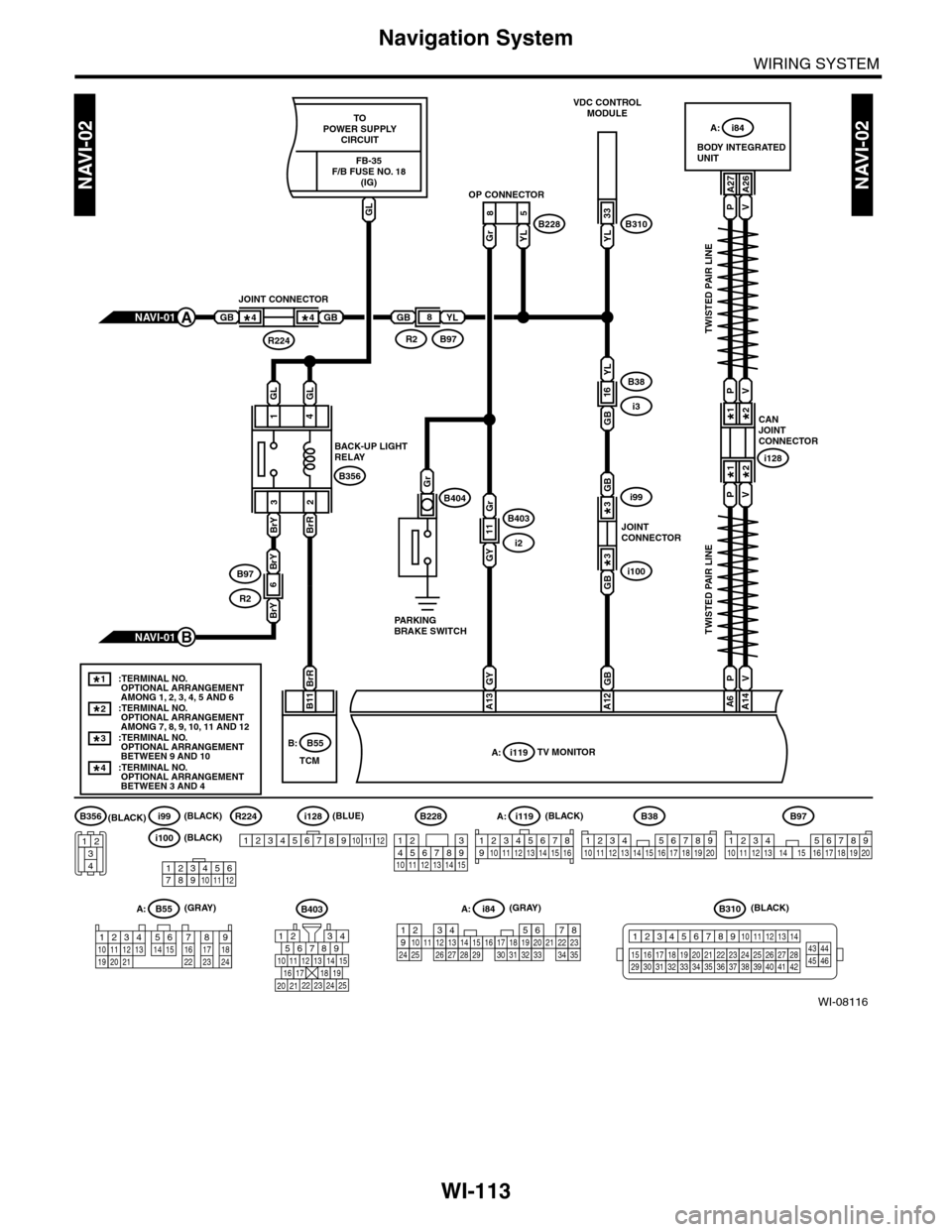
WI-113
Navigation System
WIRING SYSTEM
WI-08116
NAVI-02NAVI-02
PV
PV
123456789101112
i100(BLACK)
i99R224(BLACK)(BLACK)
(BLACK)(GRAY)
(BLUE)
YL
33
A27A26
85
GrYL
TWISTED PAIR LINE
TWISTED PAIR LINE
CANJOINTCONNECTOR
i128
1*
1*
2*
2*
B11
BODY INTEGRATEDUNIT
A: i84
VDC CONTROLMODULE
OP CONNECTOR
B310B228
A: i84
A: i119
1234567891011121415161718192021222324252627282930313233343513
PV
PV
A14A6
GB
A12
GYBrR
A13
GB
GBi100
i99
JOINTCONNECTOR
3*
3*
GB
YL
16B38
i3
GY
Gr
GB
11B403
i2
NAVI-01A
NAVI-01B
GB
JOINT CONNECTOR
R224
4*4*GBYL
B97R2
8
:TERMINAL NO. OPTIONAL ARRANGEMENT AMONG 1, 2, 3, 4, 5 AND 6:TERMINAL NO. OPTIONAL ARRANGEMENT AMONG 7, 8, 9, 10, 11 AND 12
1*
:TERMINAL NO. OPTIONAL ARRANGEMENT BETWEEN 9 AND 10
3*
:TERMINAL NO. OPTIONAL ARRANGEMENT BETWEEN 3 AND 4
4*
2*
i119TV MONITORA:B55B:
B38
1234 567891011 1213 14 15 16 17 18 19 20
B310
1234
1516171819202122232425262728293031323334353637383940414245464344568910 11 12 13 147
i128
123456789101112
B97
1234567891011 121316 17 18 19 201415
B228
131415
123456789101112
123 8910412 13 14 15 1656711
567821943
10
2422 23 25
11121314151617181920 21
B403(GRAY)A: B55
123410 11 1219 20 21135614 1578916 17 1822 23 24
(BLACK)B356
34
12
TCM
GLGL
4
BrRBrY 1
32
B356
B404Gr
BACK-UP LIGHTRELAY
PARKINGBRAKE SWITCH
BrY
BrY
6B97
R2
TOPOWER SUPPLYCIRCUIT
GL
FB-35F/B FUSE NO. 18(IG)
Page 2416 of 2453
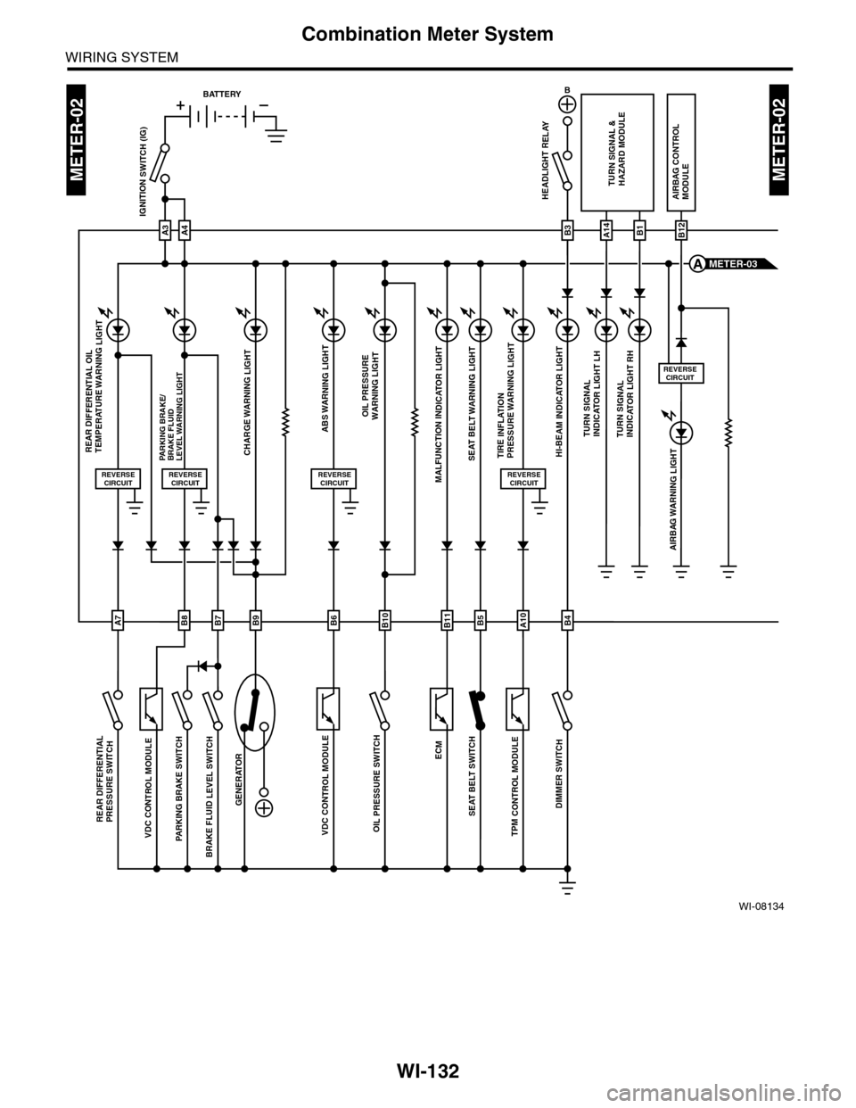
WI-132
Combination Meter System
WIRING SYSTEM
WI-08134
METER-02METER-02
ECM
TPM
CONTROL M
ODULE
VDC CONTROL M
ODULE
OIL P
RESSURE SW
ITCH
GENERATOR
BRAKE FLU
ID LEV
EL SWITCH
AIRBAG WARNING LIGHT
HEADLIGHT RELAYAIRBAG CONTROLMODULE
ABS WARNING LIGHT
CHARGE WARNING LIGHTPARKING BRAKE/BRAKE FLUIDLEVEL WARNING LIGHT
VDC CONTROL M
ODULE
PARKING BRAKE SWITCH
REAR DIFFE
RENTIAL
PRESSURE SWITCH
SEA
T BELT W
ARNING LIG
HT
SEAT BELT S
WITCH
A3
IGNITION SWITCH (IG)
A4
REVERSECIRCUIT
OIL PRESSUREWARNING LIGHT
MALFUNCTION INDICATOR LIGHT
HI-BEAM INDICATOR LIGHT
TURN SIGNAL &HAZARD MODULE
TURN SIGNALINDICATOR LIGHT LHTURN SIGNALINDICATOR LIGHT RH
REVERSECIRCUIT
REVERSECIRCUIT
B
B3A14B1B12
METER-03A
BATTERY
B8B7B9B6B10B5B4B11
REAR DIFFERENTIAL OIL TEMPERATURE WARNING LIGHT
REVERSECIRCUIT
DIMMER SWITCH
TIRE INFLATION PRESSURE WARNING LIGHT
REVERSECIRCUIT
A10A7
Page 2422 of 2453
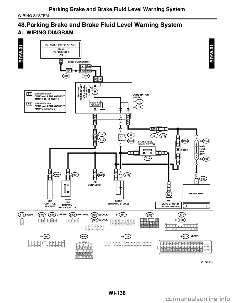
WI-138
Parking Brake and Brake Fluid Level Warning System
WIRING SYSTEM
48.Parking Brake and Brake Fluid Level Warning System
A: WIRING DIAGRAM
BR/W-01BR/W-01
WI-08140
COMBINATIONMETERPRAKINGBRAKE/BRAKEFLUID LEVELWARNINGLIGHT
12
P
18
21
B9
BW
B7
PLgR
PLgR
B8
A: i10
B: i11
LgR
B
GENERATOR
MAINFUSEBOX(M/B)
DIODE
WB
1F26
REVERSECIRCUIT
L
WB
A7
B11
F37
B143B370B:
A:
BWL
PB21
3
LgRB310Gr
PARKINGBRAKE SWITCH
DIODE(PARKING BRAKE)
B404
B16
B228B405Gr
8
P
3
Gr
4
OPCONNECTOR
BRAKE FLUIDLEVEL SWITCH
L
Gr
1
2
B143
1234 567891011 1213 14 15 16 17 18 19 20
B403B310
B16
12
B405
1234
B228
131415
123456789101112
F26
123
B370
12
F37A:
1234 5678910 11 12 13 14 15 16 17 18 19 20
B:
B38
REF. TO GROUNDCIRCUIT [GND-03]
i3
B38
FB-36F/B FUSE NO. 5(IG)
TO POWER SUPPLY CIRCUIT
BrW
A3A4
BrW
BrW
JOINT CONNECTOR
i126i127
1*
2*2*
: TERMINAL NO. OPTIONAL ARRANGEMENT AMONG 7, 8 AND 9
2*
: TERMINAL NO. OPTIONAL ARRANGEMENT AMONG 10, 11 AND 12
1*
i11
123 45678910 11 12 13 14
B:
i10
19 20 2115 16 17 182223242526272829301234568910 11 12 13 147
A:
1234
1516171819202122232425262728293031323334353637383940414245464344568910 11 12 13 147
VDCCONTROLMODULE
i2
B403
i2B403
567821943
10
2422 23 25
11121314151617181920 21
(GRAY)(GREEN) (BROWN)
(BLACK)
123456789101112
i126(BLACK)
i127(BLACK)
Page 2438 of 2453
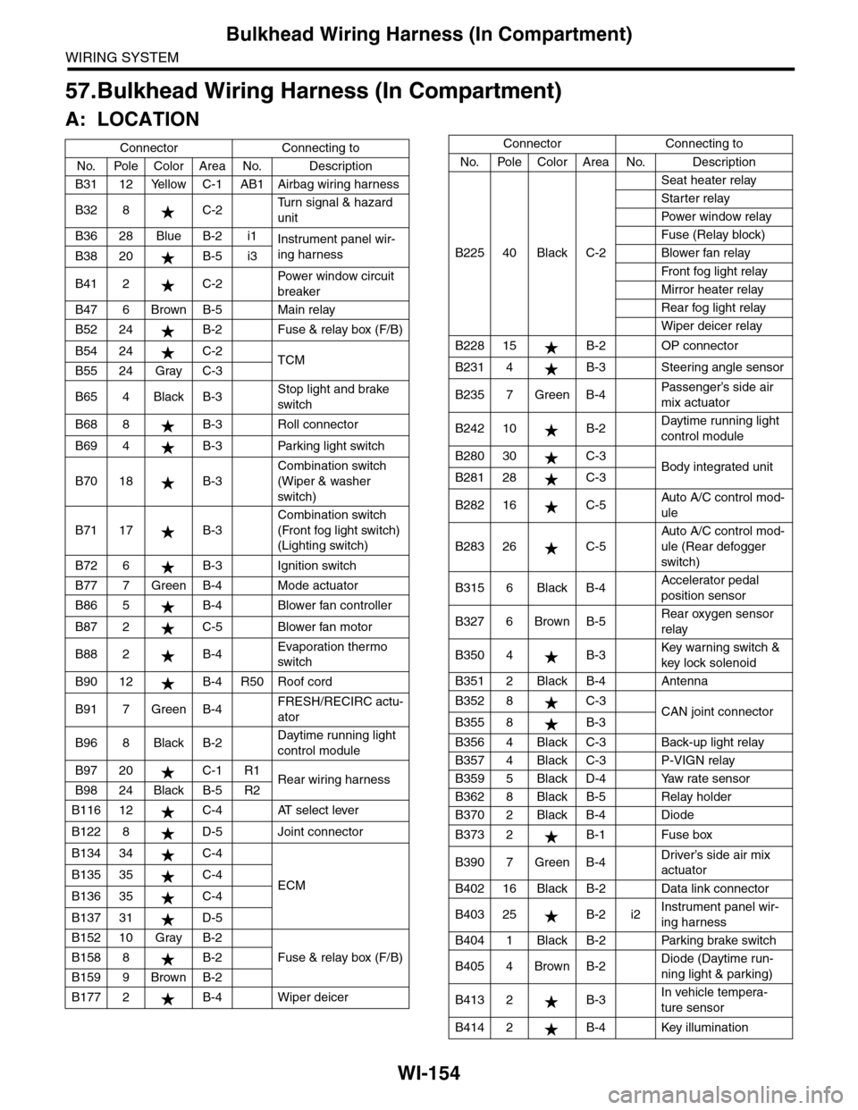
WI-154
Bulkhead Wiring Harness (In Compartment)
WIRING SYSTEM
57.Bulkhead Wiring Harness (In Compartment)
A: LOCATION
Connector Connecting to
No. Pole Color Area No. Description
B31 12 Yellow C-1 AB1 Airbag wiring harness
B32 8 C-2Tu r n s i g n a l & h a z a r d
unit
B36 28 Blue B-2 i1Instrument panel wir-
ing harnessB38 20 B-5 i3
B41 2 C-2Powe r w in d ow ci r cu i t
breaker
B47 6 Brown B-5 Main relay
B52 24 B-2 Fuse & relay box (F/B)
B54 24 C-2TCMB55 24 Gray C-3
B65 4 Black B-3Stop light and brake
switch
B68 8 B-3 Roll connector
B69 4 B-3 Parking light switch
B70 18 B-3
Combination switch
(Wiper & washer
switch)
B71 17 B-3
Combination switch
(Front fog light switch)
(Lighting switch)
B72 6 B-3 Ignition switch
B77 7 Green B-4 Mode actuator
B86 5 B-4 Blower fan controller
B87 2 C-5 Blower fan motor
B88 2 B-4Evaporation thermo
switch
B90 12 B-4 R50 Roof cord
B91 7 Green B-4FRESH/RECIRC actu-
ator
B96 8 Black B-2Daytime running light
control module
B97 20 C-1 R1Rear wiring harnessB98 24 Black B-5 R2
B116 12 C-4 AT select lever
B122 8 D-5 Joint connector
B134 34 C-4
ECMB135 35 C-4
B136 35 C-4
B137 31 D-5
B152 10 Gray B-2
Fuse & relay box (F/B)B158 8 B-2
B159 9 Brown B-2
B177 2 B-4 Wiper deicer
B225 40 Black C-2
Seat heater relay
Starter relay
Pow er w i n dow r el ay
Fuse (Relay block)
Blower fan relay
Fr o nt fog li g ht r el ay
Mirror heater relay
Rear fog light relay
Wiper deicer relay
B228 15 B-2 OP connector
B231 4 B-3 Steering angle sensor
B235 7 Green B-4Passenger’s side air
mix actuator
B242 10 B-2Daytime running light
control module
B280 30 C-3Body integrated unitB281 28 C-3
B282 16 C-5Auto A/C control mod-
ule
B283 26 C-5
Auto A/C control mod-
ule (Rear defogger
switch)
B315 6 Black B-4Accelerator pedal
position sensor
B327 6 Brown B-5Rear oxygen sensor
relay
B350 4 B-3Key war ning switch &
key lock solenoid
B351 2 Black B-4 Antenna
B352 8 C-3CAN joint connectorB355 8 B-3
B356 4 Black C-3 Back-up light relay
B357 4 Black C-3 P-VIGN relay
B359 5 Black D-4 Yaw rate sensor
B362 8 Black B-5 Relay holder
B370 2 Black B-4 Diode
B373 2 B-1 Fuse box
B390 7 Green B-4Driver’s side air mix
actuator
B402 16 Black B-2 Data link connector
B403 25 B-2 i2Instrument panel wir-
ing harness
B404 1 Black B-2 Parking brake switch
B405 4 Brown B-2Diode (Daytime run-
ning light & parking)
B413 2 B-3In vehicle tempera-
ture sensor
B414 2 B-4 Key illumination
Connector Connecting to
No. Pole Color Area No. Description