2009 SUBARU TRIBECA parking brake
[x] Cancel search: parking brakePage 1199 of 2453
EN(H6DO)(diag)-38
Inspection Mode
ENGINE (DIAGNOSTICS)
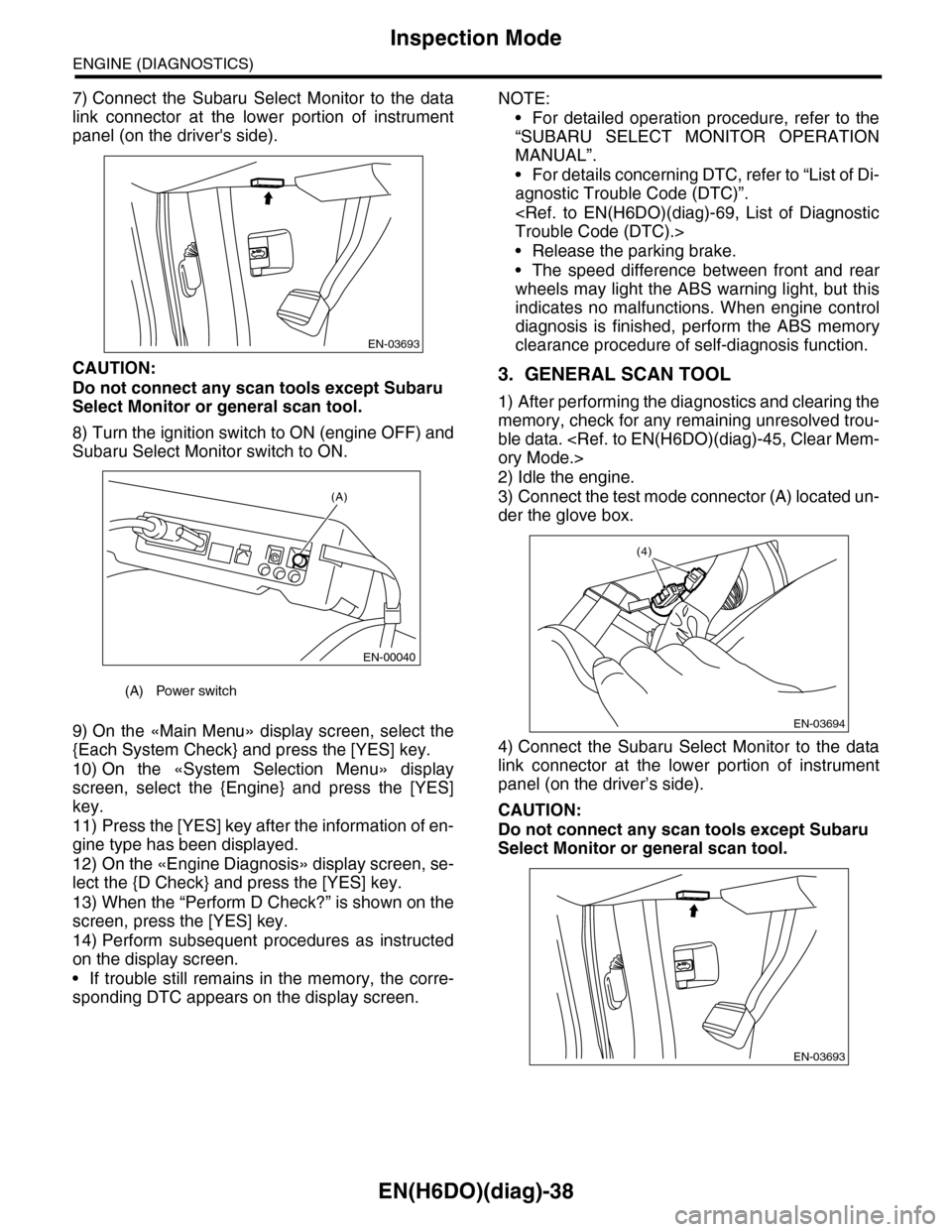
7) Connect the Subaru Select Monitor to the data
link connector at the lower portion of instrument
panel (on the driver's side).
CAUTION:
Do not connect any scan tools except Subaru
Select Monitor or general scan tool.
8) Turn the ignition switch to ON (engine OFF) and
Subaru Select Monitor switch to ON.
9) On the «Main Menu» display screen, select the
{Each System Check} and press the [YES] key.
10) On the «System Selection Menu» display
screen, select the {Engine} and press the [YES]
key.
11) Press the [YES] key after the information of en-
gine type has been displayed.
12) On the «Engine Diagnosis» display screen, se-
lect the {D Check} and press the [YES] key.
13) When the “Perform D Check?” is shown on the
screen, press the [YES] key.
14) Perform subsequent procedures as instructed
on the display screen.
•If trouble still remains in the memory, the corre-
sponding DTC appears on the display screen.
NOTE:
•For detailed operation procedure, refer to the
“SUBARU SELECT MONITOR OPERATION
MANUAL”.
•For details concerning DTC, refer to “List of Di-
agnostic Trouble Code (DTC)”.
•Release the parking brake.
•The speed difference between front and rear
wheels may light the ABS warning light, but this
indicates no malfunctions. When engine control
diagnosis is finished, perform the ABS memory
clearance procedure of self-diagnosis function.
3. GENERAL SCAN TOOL
1) After performing the diagnostics and clearing the
memory, check for any remaining unresolved trou-
ble data.
2) Idle the engine.
3) Connect the test mode connector (A) located un-
der the glove box.
4) Connect the Subaru Select Monitor to the data
link connector at the lower portion of instrument
panel (on the driver’s side).
CAUTION:
Do not connect any scan tools except Subaru
Select Monitor or general scan tool.
(A) Power switch
EN-03693
(A)
EN-00040
EN-03694
(4)
EN-03693
Page 1200 of 2453
EN(H6DO)(diag)-39
Inspection Mode
ENGINE (DIAGNOSTICS)
5) Start the engine.
NOTE:
Make sure the select lever is placed in “P” position
before starting.
6) Using the select lever, turn the “P” position
switch and the “N” position switch to ON.
7) Depress the brake pedal to turn brake switch
ON.
8) Keep the engine speed in 2,500 — 3,000 rpm
range for 40 seconds.
9) Shift the select lever in the “D” range and drive
the vehicle at 5 to 10 km/h (3 to 6 MPH).
NOTE:
•For AWD model, release the parking brake.
•The speed difference between front and rear
wheels may light the ABS warning light, but this in-
dicates no malfunctions. When engine control diag-
nosis is finished, perform the ABS memory
clearance procedure of self-diagnosis system.
10) Using the general scan tool, check DTC and
record the result(s).
NOTE:
•For detailed operation procedure, refer to the
general scan tool operation manual.
•For details concerning DTC, refer to “List of Diag-
nostic Trouble Code (DTC)”.
Page 1986 of 2453
PM-3
Schedule
PERIODIC MAINTENANCE SERVICES
2. Schedule
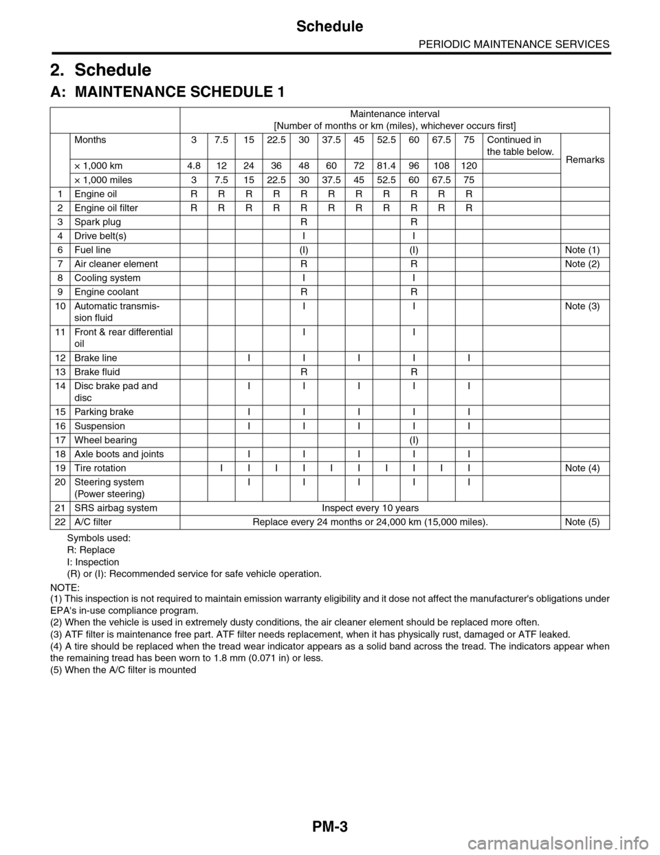
A: MAINTENANCE SCHEDULE 1
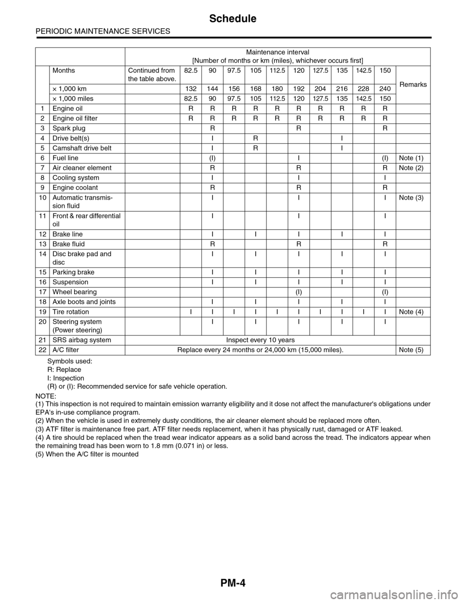
Symbols used:
R: Replace
I: Inspection
(R) or (I): Recommended service for safe vehicle operation.
NOTE:(1) This inspection is not required to maintain emission warranty eligibility and it dose not affect the manufacturer's obligations under
EPA's in-use compliance program.
(2) When the vehicle is used in extremely dusty conditions, the air cleaner element should be replaced more often.
(3) ATF filter is maintenance free part. ATF filter needs replacement, when it has physically rust, damaged or ATF leaked.
(4) A tire should be replaced when the tread wear indicator appears as a solid band across the tread. The indicators appear when
the remaining tread has been worn to 1.8 mm (0.071 in) or less.
(5) When the A/C filter is mounted
Maintenance interval
[Number of months or km (miles), whichever occurs first]
Months 3 7.51522.53037.54552.56067.575Continued in
the table below.Remarks× 1,000 km 4.8 12 24 36 48 60 72 81.4 96 108 120
× 1,000 miles 3 7.5 15 22.5 30 37.5 45 52.5 60 67.5 75
1Engine oil R R R R R R R R R R R
2Engine oil filter R R R R R R R R R R R
3Spark plug R R
4Drive belt(s) I I
6Fuel line (I) (I) Note (1)
7Air cleaner element R R Note (2)
8Cooling system I I
9Engine coolant R R
10 Automatic transmis-
sion fluid
I I Note (3)
11 Front & rear differential
oil
I I
12 Brake line I I I I I
13 Brake fluid R R
14 Disc brake pad and
disc
I I I I I
15 Parking brake I I I I I
16 Suspension I I I I I
17 Wheel bearing (I)
18 Axle boots and joints I I I I I
19 Tire rotation I I I I I I I I I I Note (4)
20 Steering system
(Power steering)
I I I I I
21 SRS airbag system Inspect every 10 years
22 A/C filter Replace every 24 months or 24,000 km (15,000 miles). Note (5)
Page 1987 of 2453
PM-4
Schedule
PERIODIC MAINTENANCE SERVICES
Symbols used:
R: Replace
I: Inspection
(R) or (I): Recommended service for safe vehicle operation.
NOTE:(1) This inspection is not required to maintain emission warranty eligibility and it dose not affect the manufacturer's obligations under
EPA's in-use compliance program.
(2) When the vehicle is used in extremely dusty conditions, the air cleaner element should be replaced more often.
(3) ATF filter is maintenance free part. ATF filter needs replacement, when it has physically rust, damaged or ATF leaked.
(4) A tire should be replaced when the tread wear indicator appears as a solid band across the tread. The indicators appear when
the remaining tread has been worn to 1.8 mm (0.071 in) or less.
(5) When the A/C filter is mounted
Maintenance interval
[Number of months or km (miles), whichever occurs first]
Months Continued from
the table above.
82.5 90 97.5 105112.5120127.5135142.5150
Remarks× 1,000 km 132 144 156 168 180 192 204 216 228 240
× 1,000 miles 82.5 90 97.5 105112.5120127.5135142.5150
1Engine oil R R R R R R R R R R
2Engine oil filter R R R R R R R R R R
3Spark plug R R R
4Drive belt(s) I R I
5Camshaft drive belt I R I
6Fuel line (I) I (I) Note (1)
7Air cleaner element R R R Note (2)
8Cooling system I I I
9Engine coolant R R R
10 Automatic transmis-
sion fluid
I I INote (3)
11 Front & rear differential
oil
I I I
12 Brake line I I I I I
13 Brake fluid R R R
14 Disc brake pad and
disc
I I I I I
15 Parking brake I I I I I
16 Suspension I I I I I
17 Wheel bearing (I) (I)
18 Axle boots and joints I I I I I
19 Tire rotation I I I I I I I I I I Note (4)
20 Steering system
(Power steering)
I I I I I
21 SRS airbag system Inspect every 10 years
22 A/C filter Replace every 24 months or 24,000 km (15,000 miles). Note (5)
Page 2006 of 2453
PM-23
Parking Brake
PERIODIC MAINTENANCE SERVICES
16.Parking Brake
A: INSPECTION
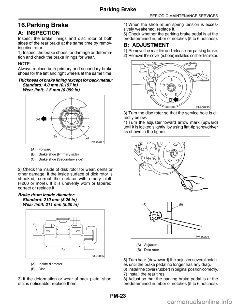
Inspect the brake linings and disc rotor of both
sides of the rear brake at the same time by remov-
ing disc rotor.
1) Inspect the brake shoes for damage or deforma-
tion and check the brake linings for wear.
NOTE:
Always replace both primary and secondary brake
shoes for the left and right wheels at the same time.
Thickness of brake lining (except for back metal):
Standard: 4.0 mm (0.157 in)
Wear limit: 1.5 mm (0.059 in)
2) Check the inside of disk rotor for wear, dents or
other damage. If the inside surface of dick rotor is
streaked, correct the surface with emery cloth
(#200 or more). If it is unevenly worn or tapered,
correct or replace it.
Brake drum inside diameter:
Standard: 210 mm (8.26 in)
Wear limit: 211 mm (8.30 in)
3) If the deformation or wear of back plate, shoe,
etc. is noticeable, replace them.
4) When the shoe return spring tension is exces-
sively weakened, replace it.
5) Check whether the parking brake pedal is at the
predetermined number of notches (5 to 6 notches).
B: ADJUSTMENT
1) Remove the rear tire and release the parking brake.
2) Remove the cover (rubber) installed on the disc rotor.
3) Turn the disc rotor so that the service hole is di-
rectly below.
4) Turn the adjuster toward arrow mark (upward)
until it is locked slightly, by using flat-tip screwdriver
as shown in the figure.
5) Turn back (downward) the adjuster several notch-
es until the brake pedal no longer has any drag.
6) Install the cover (rubber) in original position correctly.
7) Install the rear tires.
8) Adjust so that the parking brake pedal is at the
predetermined number of notches (5 to 6 notches).
(A) Forward
(B) Brake shoe (Primary side)
(C) Brake shoe (Secondary side)
(A) Inside diameter
(B) Disc
PM-00317
(A)
(B)(C)
PM-00055
(A)
(B)
(A) Adjuster
(B) Disc rotor
PM-00290
PM-00291
(A)(B)
Page 2041 of 2453
5AT-25
General Description
AUTOMATIC TRANSMISSION
2. GENERAL TOOL
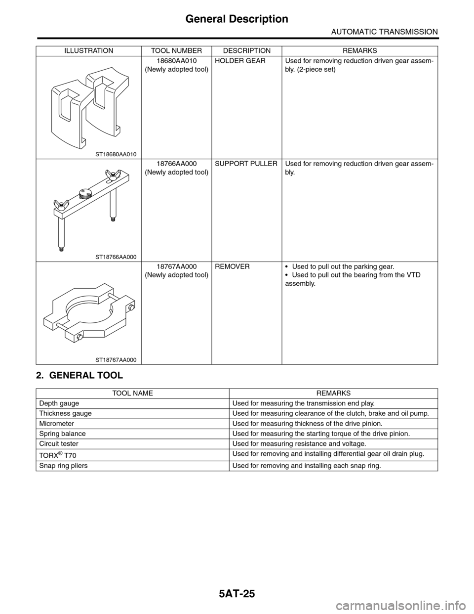
18680AA010
(Newly adopted tool)
HOLDER GEAR Used for removing reduction driven gear assem-
bly. (2-piece set)
18766AA000
(Newly adopted tool)
SUPPORT PULLER Used for removing reduction driven gear assem-
bly.
18767AA000
(Newly adopted tool)
REMOVER • Used to pull out the parking gear.
•Used to pull out the bearing from the VTD
assembly.
TO OL N AM E RE MA R KS
Depth gauge Used for measuring the transmission end play.
Thickness gauge Used for measuring clearance of the clutch, brake and oil pump.
Micrometer Used for measuring thickness of the drive pinion.
Spring balance Used for measuring the starting torque of the drive pinion.
Circuit tester Used for measuring resistance and voltage.
TO RX® T70Used for removing and installing differential gear oil drain plug.
Snap ring pliers Used for removing and installing each snap ring.
ILLUSTRATION TOOL NUMBER DESCRIPTION REMARKS
ST18680AA010
ST18766AA000
ST18767AA000
Page 2045 of 2453
5AT-29
Road Test
AUTOMATIC TRANSMISSION
4. Road Test
A: INSPECTION
1. GENERAL PRECAUTION
Road tests should be conducted to properly diag-
nose the condition of automatic transmission.
NOTE:
When performing the test, do not exceed posted
speed limit.
2. D RANGE SHIFT FUNCTION
Check shifting between 1st ←→ 2nd ←→ 3rd ←→
4th ←→ 5th while driving on normal city streets.
3. D RANGE SHIFT SHOCK
Check the shock level when shifting up during nor-
mal driving.
4. KICK–DOWN FUNCTION
Check kick–down for each gear. Check the shock
level during kick–down at the same time.
5. ENGINE BRAKE OPERATION
•Check the 4th gear engine brake when shifting
down from 5th to 4th range while driving in 5th gear
of manual mode [50 to 60 km/h (31 to 37 MPH)].
•Check the 3rd gear engine brake when shifting
down from 4th to 3rd range while driving in 4th gear
of manual mode [50 — 60 km/h (31 — 37 MPH)].
•Check the 2nd gear engine brake when shifting
down from 3rd to 2nd range while driving in 3rd
gear of manual mode [40 — 50 km/h (25 — 31
MPH)].
•Check the 1st gear engine brake when shifting
down from 2nd to 1st range while driving in 2nd
gear of manual mode [20 — 30 km/h (12 — 19
MPH)].
6. P RANGE OPERATION
Stop the vehicle on an uphill grade of 5% or more
and shift to the “P” range. Check that the vehicle
does not move when the parking brake is released.
7. NOISE AND VIBRATION
Check for noise and vibration while driving and dur-
ing shifting.
8. OIL LEAKAGE
After the driving test, inspect for oil leaks from the
transmission body.
Page 2046 of 2453
5AT-30
Stall Test
AUTOMATIC TRANSMISSION
5. Stall Test
A: INSPECTION
NOTE:
The stall test is extremely important in diagnosing
the condition of an automatic transmission and en-
gine. It should be conducted to measure the engine
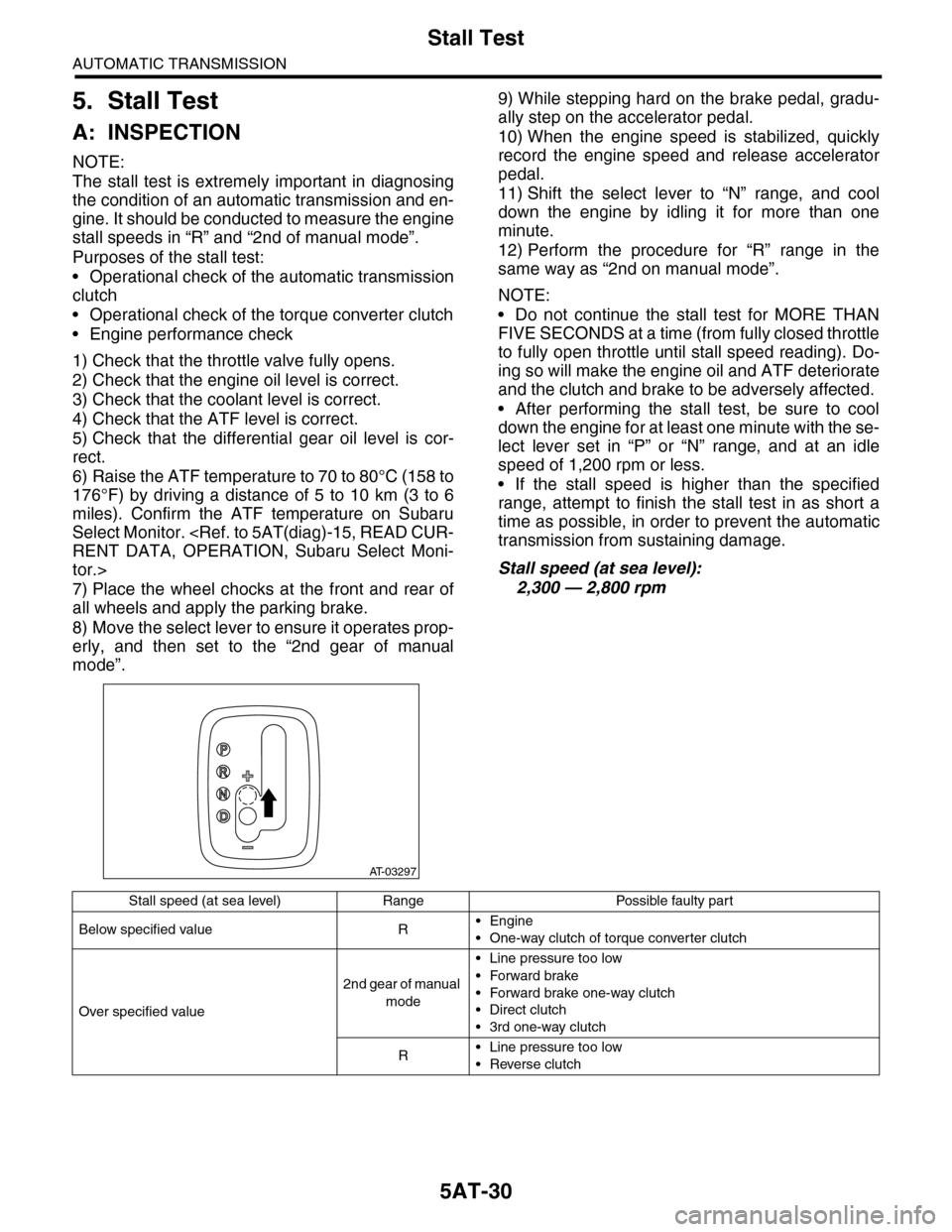
stall speeds in “R” and “2nd of manual mode”.
Purposes of the stall test:
•Operational check of the automatic transmission
clutch
•Operational check of the torque converter clutch
•Engine performance check
1) Check that the throttle valve fully opens.
2) Check that the engine oil level is correct.
3) Check that the coolant level is correct.
4) Check that the ATF level is correct.
5) Check that the differential gear oil level is cor-
rect.
6) Raise the ATF temperature to 70 to 80°C (158 to
176°F) by driving a distance of 5 to 10 km (3 to 6
miles). Confirm the ATF temperature on Subaru
Select Monitor.
tor.>
7) Place the wheel chocks at the front and rear of
all wheels and apply the parking brake.
8) Move the select lever to ensure it operates prop-
erly, and then set to the “2nd gear of manual
mode”.
9) While stepping hard on the brake pedal, gradu-
ally step on the accelerator pedal.
10) When the engine speed is stabilized, quickly
record the engine speed and release accelerator
pedal.
11) Shift the select lever to “N” range, and cool
down the engine by idling it for more than one
minute.
12) Perform the procedure for “R” range in the
same way as “2nd on manual mode”.
NOTE:
•Do not continue the stall test for MORE THAN
FIVE SECONDS at a time (from fully closed throttle
to fully open throttle until stall speed reading). Do-
ing so will make the engine oil and ATF deteriorate
and the clutch and brake to be adversely affected.
•After performing the stall test, be sure to cool
down the engine for at least one minute with the se-
lect lever set in “P” or “N” range, and at an idle
speed of 1,200 rpm or less.
•If the stall speed is higher than the specified
range, attempt to finish the stall test in as short a
time as possible, in order to prevent the automatic
transmission from sustaining damage.
Stall speed (at sea level):
2,300 — 2,800 rpm
AT-03297
Stall speed (at sea level) Range Possible faulty part
Below specified value R•Engine
•One-way clutch of torque converter clutch
Over specified value
2nd gear of manual
mode
•Line pressure too low
•Forward brake
•Forward brake one-way clutch
•Direct clutch
•3rd one-way clutch
R•Line pressure too low
•Reverse clutch