2009 SUBARU TRIBECA parking brake
[x] Cancel search: parking brakePage 880 of 2453

PB-9
Parking Brake Assembly (Rear Disc Brake)
PARKING BRAKE
D: ADJUSTMENT
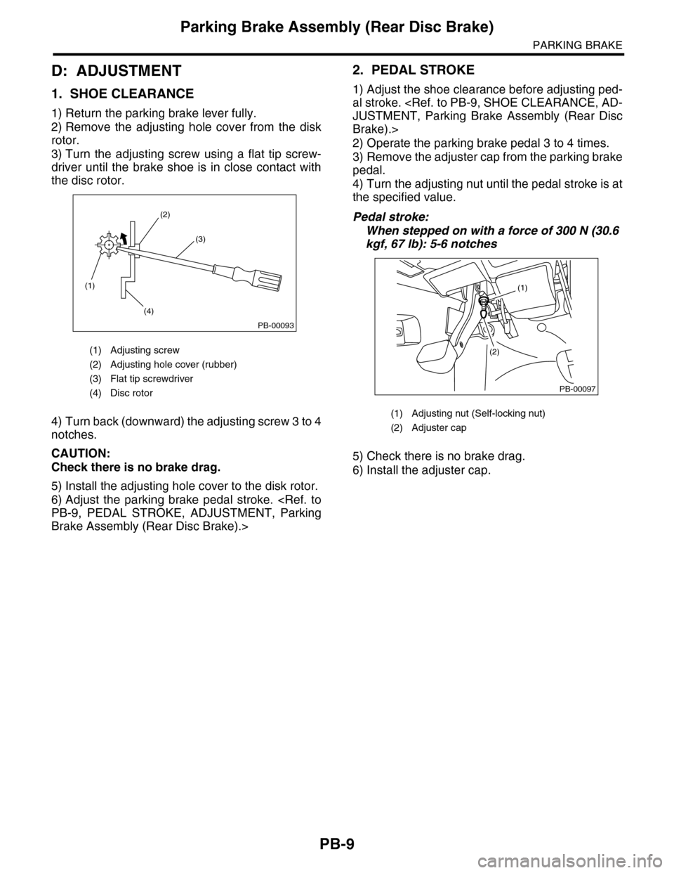
1. SHOE CLEARANCE
1) Return the parking brake lever fully.
2) Remove the adjusting hole cover from the disk
rotor.
3) Turn the adjusting screw using a flat tip screw-
driver until the brake shoe is in close contact with
the disc rotor.
4) Turn back (downward) the adjusting screw 3 to 4
notches.
CAUTION:
Check there is no brake drag.
5) Install the adjusting hole cover to the disk rotor.
6) Adjust the parking brake pedal stroke.
Brake Assembly (Rear Disc Brake).>
2. PEDAL STROKE
1) Adjust the shoe clearance before adjusting ped-
al stroke.
Brake).>
2) Operate the parking brake pedal 3 to 4 times.
3) Remove the adjuster cap from the parking brake
pedal.
4) Turn the adjusting nut until the pedal stroke is at
the specified value.
Pedal stroke:
When stepped on with a force of 300 N (30.6
kgf, 67 lb): 5-6 notches
5) Check there is no brake drag.
6) Install the adjuster cap.
(1) Adjusting screw
(2) Adjusting hole cover (rubber)
(3) Flat tip screwdriver
(4) Disc rotor
(1)
(4)
(2)
(3)
PB-00093
(1) Adjusting nut (Self-locking nut)
(2) Adjuster cap
PB-00097
(1)
(2)
Page 881 of 2453

PB-10
General Diagnostic Table
PARKING BRAKE
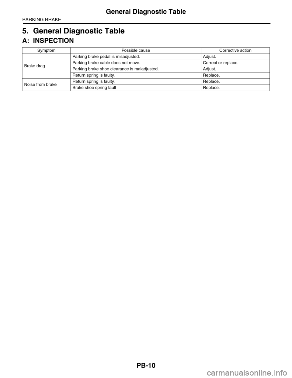
5. General Diagnostic Table
A: INSPECTION
Symptom Possible cause Corrective action
Brake drag
Par king brake pedal is misadjusted. Adjust.
Par king brake cable does not move. Correct or replace.
Par king brake shoe clearance is maladjusted. Adjust.
Return spring is faulty. Replace.
Noise from brakeReturn spring is faulty. Replace.
Brake shoe spring fault Replace.
Page 930 of 2453

PS-50
General Diagnostic Table
POWER ASSISTED SYSTEM (POWER STEERING)
1. NOISE & VIBRATION
CAUTION:
Do not keep the relief valve operated over five seconds at any time or inner parts of the oil pump may
be damaged due to rapid increase of fluid temperature.
NOTE:
•A screeching noise may be heard immediately after the engine start in extremely cold conditions. In this
case, if the noise goes off during warm-up there is no abnormal function in the system. This is due to the fluid
characteristics in extremely cold condition.
•The oil pump normally makes a small whining noise due to its mechanism. Even if a noise is heard when
steering wheel is turned at stand still, there is no abnormal function in the system provided that the noise
eliminates when the vehicle is driving.
•When turning the steering wheel with the brake applied when the vehicle is parked, a screeching noise
may be generated by the brake disc and pads. This is not a fault in the steering system.
•There may be a small vibration around the steering devices when turning the steering wheel at standstill,
even though the component parts are operating properly.
Hydraulic systems are likely to generate this kind of vibration as well as working noise and fluid noise be-
cause of combined conditions, i.e., road surface and tire surface, engine speed and turning speed of steering
wheel, fluid temperature and braking condition.
These conditions do not indicate a problem in the system.
Confirm vibration for an AT model, by applying the parking brake on a concrete surface, shifting into the “D”
range, and turning the steering wheel repeatedly from slow to rapid, step by step.
Tr o u b l e P o s s i b l e c a u s e C o r r e c t i v e a c t i o n
Hiss noise (continuous)
While engine is running.
Relief valve emits operating sound when steering wheel is
completely turned in either direction. (Do not keep this
condition over five seconds.)
Normal
Relief valve emits operating sound when steering wheel is
not turned. This means that the relief valve is defective. Replace the oil pump.
Rattling noise (intermittent)
While engine is running.
Interference with adjacent parts
Check the clearance.
Correct if necessary.
Loosened installation of oil pump, oil tank, pump bracket,
gearbox or crossmemberRetighten.
Loose oil pump pulley or other pulley(s) Retighten.
Looseness of linkage, play of steering, improper tightening
(looseness) of suspension joint or steering columnRetighten or replace.
Sound generates from the inside of gearbox or oil pump.Replace faulty parts in the gear-
box or oil pump.
Knocking
When turning steering wheel in
both directions with small angle
repeatedly at engine ON or OFF.
Excessive backlash
Loosened lock nut for adjusting backlashAdjust and retighten.
Insufficient tightening or play in the tie–rod or tie–rod end Retighten or replace.
Grinding noise (continuous)
While engine is running.
Air in vane pump
Inspect and retighten the fluid
line connection.
Refill the fluid and vent air.
Va n e p u m p s e i z i n g R e p l a c e t h e o i l p u m p.
Oil pump pulley bearing seized Replace the oil pump.
Folded hose, flattened pipe Replace.
Squeal, squeak (intermittent or
continuous)
While engine is running.
Improper adjustment of pulley belt
Damaged or over tensioned pulley belt
Unequal length of pulley belts
Adjust or replace.
(Replace two belts as a set.)
Runout or dirty V–groove surface of oil pump pulley Clean or replace.
Page 931 of 2453

PS-51
General Diagnostic Table
POWER ASSISTED SYSTEM (POWER STEERING)
Sizzling noise (continuous)
While engine is running.
Fluid aeration
Fix the faulty part causing aera-
tion.
Replace the fluid and vent air.
Damaged pipe of gearbox Replace the pipe.
Fa u lt y i n si de of h os e o r pi p e
Flattened hose or pipeRepair or replace.
Abnormal inside of oil tank Replace.
Removed oil tank cap Install cap.
Whistle (continuous)
While engine is running.Fa u lt y p i pe of g ea r b ox o r fa ul t y h os eReplace the faulty parts of the
gearbox or the hose.
Whine or growl (intermittent or
continuous)
While engine is running with/
without steering turned.
Looseness of oil pump, oil pump bracket attachment Retighten.
Fa u lt in s id e o f oi l p u mp o r h os e
Replace the oil pump or hose, if
the noise can be heard when
vehicle is running as well as
being stopped.
To r q u e c o n v e r t e r g r o w l , a i r c o n d i t i o n e r c o m p r e s s i o n g r o w lRemove the power steering pul-
ley belt and check.
Grinding noise (continuous)
While engine is running with the
steering turned.
Fa u lt in s id e o f ge a rb oxReplace the faulty parts of gear-
box.
Fa u lt y s t ee r i ng sh af t b ea r i ng A pp l y gr ea s e o r r e p la ce.
Occurs when turning the steering wheel with brakes (ser-
vice or parking) applied.
If the noise goes off when brake
is released, it is normal.
Vibration
While engine is running with/
without steering turned.
Engine speed is too low. Adjust, and notify customer.
Air in vane pumpRepair faulty part
Ve n t a i r.
Damaged valve in oil pump or gearboxReplace the faulty parts in gear-
box and oil pump.
Excessive play in steering, looseness of suspension parts Retighten.
Tr o u b l e P o s s i b l e c a u s e C o r r e c t i v e a c t i o n
Page 942 of 2453

RS-9
Rear Trailing Link
REAR SUSPENSION
4. Rear Trailing Link
A: REMOVAL
1) Lift-up the vehicle, and then remove the rear
wheels.
2) Remove the bracket, and remove the parking
brake cable from the guide.
3) Remove the ABS wheel speed sensor harness
from the trailing link.
4) Remove the trailing link.
B: INSTALLATION
NOTE:
•Be sure to use a new self-locking nut.
•Always tighten the stabilizer bushing in the state
where the vehicle is at curb weight and the wheels
are in full contact with the ground.
Install in the reverse order of removal.
Tightening torque:
Trailing link
120 N·m (12.2 kgf-m, 89 ft-lb)
Parking Brake Cable bracket
33 N·m (3.4 kgf-m, 24 ft-lb)
C: DISASSEMBLY
Using the ST and a pipe, press the bushing out.
ST 20099PA010 INSTALLER & REMOVER
(1) Guide
RS-00180
(1)
RS-00181
(1) 39 mm dia., 50 mm long pipe
(2) Trailing link
RS-00182
ST
(2)
(1)
Page 949 of 2453

RS-16
Rear Sub Frame
REAR SUSPENSION
9. Rear Sub Frame
A: REMOVAL
1) Separate the front exhaust pipe and rear ex-
haust pipe.
2) Remove the rear exhaust pipe and muffler.
3) Remove the propeller shaft.
4) Remove the spare tire hoist.
5) Remove the rear parking brake cable from the
parking brake assembly.
6) Detach the brake hose, and remove the rear
brake caliper from the vehicle.
7) Disconnect the ABS wheel speed sensor con-
nector.
8) Remove the bolts on the bottom side of the
shock absorber.
9) Support the sub frame using a jack.
10) Remove the front sub frame.
11) Remove the rear sub frame support.
12) Remove the rear sub frame.
B: INSTALLATION
NOTE:
•Be sure to use a new self-locking nut.
•Always tighten the stabilizer bushing in the state
where the vehicle is at curb weight and the wheels
are in full contact with the ground.
1) Install in the reverse order of removal.
Tightening torque:
Refer to “COMPONENT” of “General Descrip-
tion” for the tightening torque.
2) Bleed air from brake system.
3) Inspect the wheel alignment and adjust if neces-
sary.
C: INSPECTION
Check the removed parts for wear, damage and
crack, and repair or replace them if faulty.
RS-00194
RS-00195
RS-00196
RS-00197
RS-00198
Page 1007 of 2453

VDC(diag)-15
Control Module I/O Signal
VEHICLE DYNAMICS CONTROL (VDC) (DIAGNOSTICS)
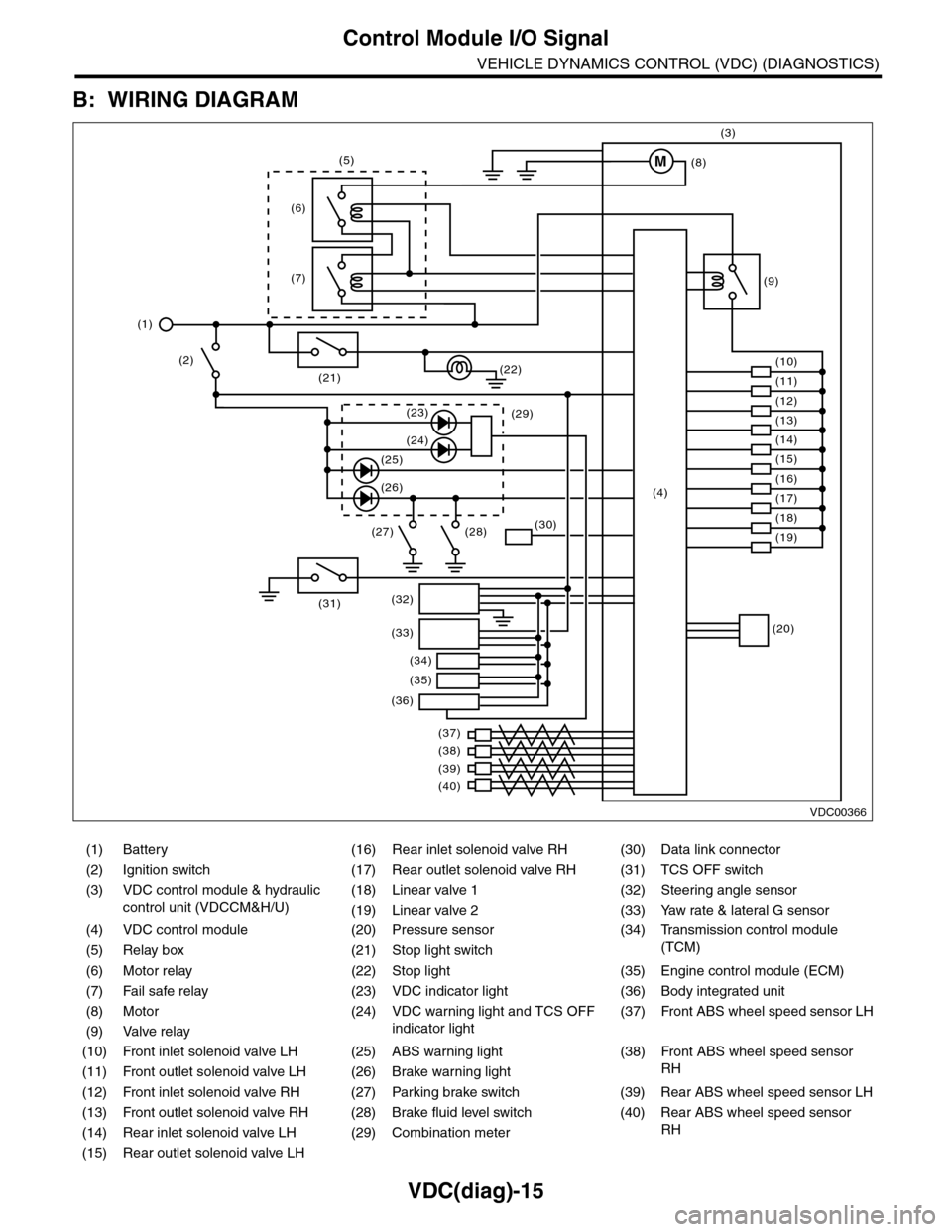
B: WIRING DIAGRAM
(1) Battery (16) Rear inlet solenoid valve RH (30) Data link connector
(2) Ignition switch (17) Rear outlet solenoid valve RH (31) TCS OFF switch
(3) VDC control module & hydraulic
control unit (VDCCM&H/U)
(18) Linear valve 1 (32) Steering angle sensor
(19) Linear valve 2 (33) Yaw rate & lateral G sensor
(4) VDC control module (20) Pressure sensor (34)
Tr a n s m i s s i o n c o n t r o l m o d u l e
(TCM)(5) Relay box (21) Stop light switch
(6) Motor relay (22) Stop light (35) Engine control module (ECM)
(7) Fail safe relay (23) VDC indicator light (36) Body integrated unit
(8) Motor (24) VDC warning light and TCS OFF
indicator light
(37)
Fr o nt A B S w he e l sp ee d se n so r L H
(9) Valve relay
(10) Front inlet solenoid valve LH (25) ABS warning light (38)
Fr o nt A B S w he e l sp e ed se n so r
RH(11) Front outlet solenoid valve LH (26) Brake warning light
(12) Front inlet solenoid valve RH (27) Parking brake switch (39) Rear ABS wheel speed sensor LH
(13) Front outlet solenoid valve RH (28) Brake fluid level switch (40) Rear ABS wheel speed sensor
RH(14) Rear inlet solenoid valve LH (29) Combination meter
(15) Rear outlet solenoid valve LH
VDC00366
M
(17)(4)(16)
(19)
(20)
(18)
(38)
(37)
(32)
(33)
(36)
(34)
(35)
(40)
(39)
(15)
(14)
(13)
(12)
(7)
(22)(21)
(31)
(23)(29)
(24)
(25)
(26)
(27) (28)(30)
(1)
(2)
(6)
(11)
(10)
(9)
(8)
(3)
(5)
Page 1017 of 2453

VDC(diag)-25
Warning Light Illumination Pattern
VEHICLE DYNAMICS CONTROL (VDC) (DIAGNOSTICS)
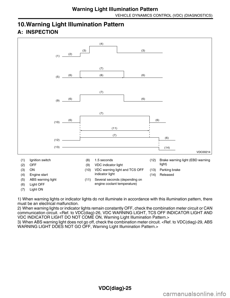
10.Warning Light Illumination Pattern
A: INSPECTION
1) When warning lights or indicator lights do not illuminate in accordance with this illumination pattern, there
must be an electrical malfunction.
2) When warning lights or indicator lights remain constantly OFF, check the combination meter circuit or CAN
communication circuit.
3) When ABS warning light does not go off, check the combination meter circuit.
(1) Ignition switch (8) 1.5 seconds (12) Brake warning light (EBD warning
light)(2) OFF (9) VDC indicator light
(3) ON (10) VDC warning light and TCS OFF
indicator light
(13) Parking brake
(4) Engine start (14) Released
(5) ABS warning light (11) Several seconds (depending on
engine coolant temperature)(6) Light OFF
(7) Light ON
VDC00214
(2)
(6) (6)
(7)
(6) (6)
(7)
(8)
(6) (6)
(7)
(11)
(3) (3)
(4)
(1)
(5)
(9)
(10)
(6)(7)
(12)
(14)(13)