2009 SUBARU TRIBECA parking brake
[x] Cancel search: parking brakePage 1019 of 2453
VDC(diag)-27
Warning Light Illumination Pattern
VEHICLE DYNAMICS CONTROL (VDC) (DIAGNOSTICS)
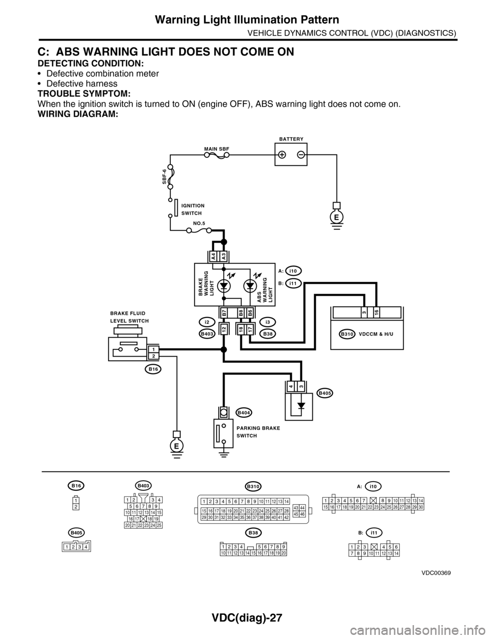
C: ABS WARNING LIGHT DOES NOT COME ON
DETECTING CONDITION:
•Defective combination meter
•Defective harness
TROUBLE SYMPTOM:
When the ignition switch is turned to ON (engine OFF), ABS warning light does not come on.
WIRING DIAGRAM:
B16
12
B38
E
MAIN SBF
SBF-6
E
NO.5
B16
B404
A3A4
12
34B405
1234 5678910 11 12 13 14 15 16 17 18 19 20
BATTERY
IGNITIONSWITCH
BRAKE FLUIDLEVEL SWITCH
PARKING BRAKESWITCH
BRAKEWARNINGLIGHTABSWARNINGLIGHT
316
B310B38
i3
i10A:
i11B:
VDCCM & H/U
B8
1817B403
i2B7B6
VDC00369
12
B405
1234
B403
567821943
10
2422 23 25
1112131415161718192021
B310
1234
1516171819202122232425262728293031323334353637383940414245464344568910 11 12 13 147
1234567891011121314
i11B:
123456789101112131415161718192021222324252627282930
i10A:
Page 1021 of 2453
VDC(diag)-29
Warning Light Illumination Pattern
VEHICLE DYNAMICS CONTROL (VDC) (DIAGNOSTICS)
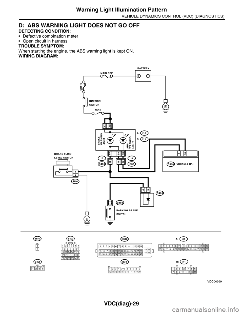
D: ABS WARNING LIGHT DOES NOT GO OFF
DETECTING CONDITION:
•Defective combination meter
•Open circuit in harness
TROUBLE SYMPTOM:
When starting the engine, the ABS warning light is kept ON.
WIRING DIAGRAM:
B16
12
B38
E
MAIN SBF
SBF-6
E
NO.5
B16
B404
A3A4
12
34B405
1234 5678910 11 12 13 14 15 16 17 18 19 20
BATTERY
IGNITIONSWITCH
BRAKE FLUIDLEVEL SWITCH
PARKING BRAKESWITCH
BRAKEWARNINGLIGHTABSWARNINGLIGHT
316
B310B38
i3
i10A:
i11B:
VDCCM & H/U
B8
1817B403
i2B7B6
VDC00369
12
B405
1234
B403
567821943
10
2422 23 25
1112131415161718192021
B310
1234
1516171819202122232425262728293031323334353637383940414245464344568910 11 12 13 147
1234567891011121314
i11B:
123456789101112131415161718192021222324252627282930
i10A:
Page 1024 of 2453
VDC(diag)-32
Warning Light Illumination Pattern
VEHICLE DYNAMICS CONTROL (VDC) (DIAGNOSTICS)
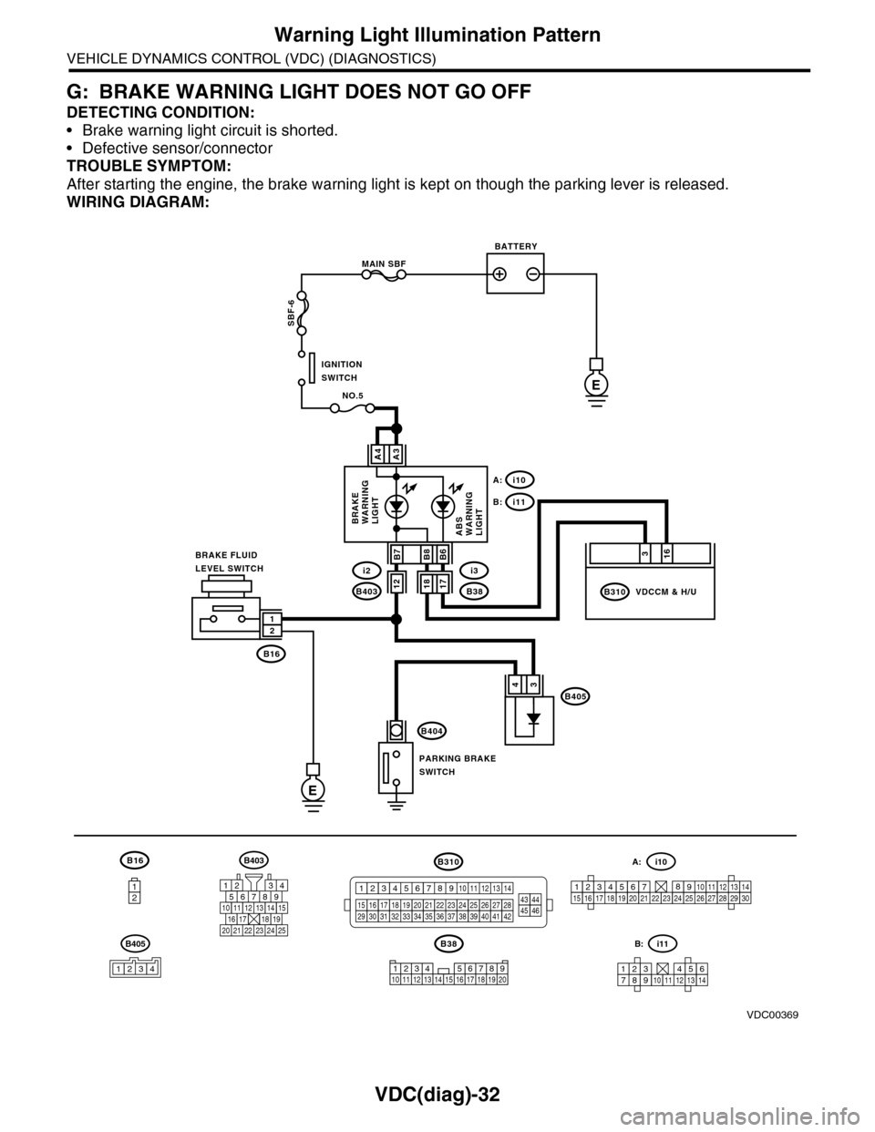
G: BRAKE WARNING LIGHT DOES NOT GO OFF
DETECTING CONDITION:
•Brake warning light circuit is shorted.
•Defective sensor/connector
TROUBLE SYMPTOM:
After starting the engine, the brake warning light is kept on though the parking lever is released.
WIRING DIAGRAM:
B16
12
B38
E
MAIN SBF
SBF-6
E
NO.5
B16
B404
A3A4
12
34B405
1234 5678910 11 12 13 14 15 16 17 18 19 20
BATTERY
IGNITIONSWITCH
BRAKE FLUIDLEVEL SWITCH
PARKING BRAKESWITCH
BRAKEWARNINGLIGHTABSWARNINGLIGHT
316
B310B38
i3
i10A:
i11B:
VDCCM & H/U
B8
1817B403
i2B7B6
VDC00369
12
B405
1234
B403
567821943
10
2422 23 25
1112131415161718192021
B310
1234
1516171819202122232425262728293031323334353637383940414245464344568910 11 12 13 147
1234567891011121314
i11B:
123456789101112131415161718192021222324252627282930
i10A:
Page 1025 of 2453
VDC(diag)-33
Warning Light Illumination Pattern
VEHICLE DYNAMICS CONTROL (VDC) (DIAGNOSTICS)
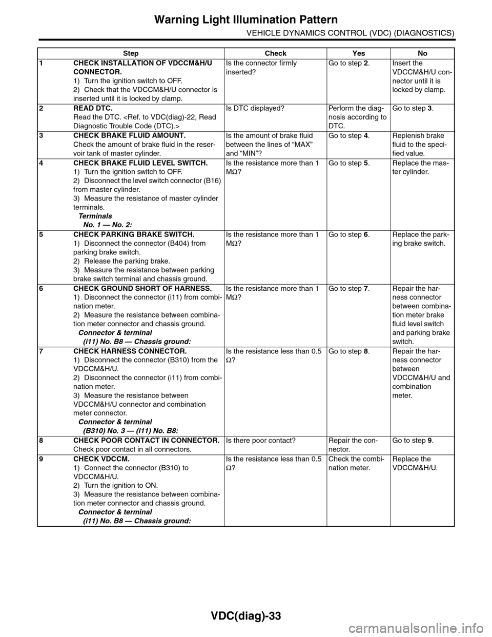
Step Check Yes No
1CHECK INSTALLATION OF VDCCM&H/U
CONNECTOR.
1) Turn the ignition switch to OFF.
2) Check that the VDCCM&H/U connector is
inserted until it is locked by clamp.
Is the connector firmly
inserted?
Go to step 2.Insert the
VDCCM&H/U con-
nector until it is
locked by clamp.
2READ DTC.
Read the DTC.
Is DTC displayed? Perform the diag-
nosis according to
DTC.
Go to step 3.
3CHECK BRAKE FLUID AMOUNT.
Check the amount of brake fluid in the reser-
voir tank of master cylinder.
Is the amount of brake fluid
between the lines of “MAX”
and “MIN”?
Go to step 4.Replenish brake
fluid to the speci-
fied value.
4CHECK BRAKE FLUID LEVEL SWITCH.
1) Turn the ignition switch to OFF.
2) Disconnect the level switch connector (B16)
from master cylinder.
3) Measure the resistance of master cylinder
terminals.
Te r m i n a l s
No. 1 — No. 2:
Is the resistance more than 1
MΩ?
Go to step 5.Replace the mas-
ter cylinder.
5CHECK PARKING BRAKE SWITCH.
1) Disconnect the connector (B404) from
parking brake switch.
2) Release the parking brake.
3) Measure the resistance between parking
brake switch terminal and chassis ground.
Is the resistance more than 1
MΩ?
Go to step 6.Replace the park-
ing brake switch.
6CHECK GROUND SHORT OF HARNESS.
1) Disconnect the connector (i11) from combi-
nation meter.
2) Measure the resistance between combina-
tion meter connector and chassis ground.
Connector & terminal
(i11) No. B8 — Chassis ground:
Is the resistance more than 1
MΩ?
Go to step 7.Repair the har-
ness connector
between combina-
tion meter brake
fluid level switch
and parking brake
switch.
7CHECK HARNESS CONNECTOR.
1) Disconnect the connector (B310) from the
VDCCM&H/U.
2) Disconnect the connector (i11) from combi-
nation meter.
3) Measure the resistance between
VDCCM&H/U connector and combination
meter connector.
Connector & terminal
(B310) No. 3 — (i11) No. B8:
Is the resistance less than 0.5
Ω?
Go to step 8.Repair the har-
ness connector
between
VDCCM&H/U and
combination
meter.
8CHECK POOR CONTACT IN CONNECTOR.
Check poor contact in all connectors.
Is there poor contact? Repair the con-
nector.
Go to step 9.
9CHECK VDCCM.
1) Connect the connector (B310) to
VDCCM&H/U.
2) Turn the ignition to ON.
3) Measure the resistance between combina-
tion meter connector and chassis ground.
Connector & terminal
(i11) No. B8 — Chassis ground:
Is the resistance less than 0.5
Ω?
Check the combi-
nation meter.
Replace the
VDCCM&H/U.
Page 1079 of 2453
VDC(diag)-87
General Diagnostic Table
VEHICLE DYNAMICS CONTROL (VDC) (DIAGNOSTICS)
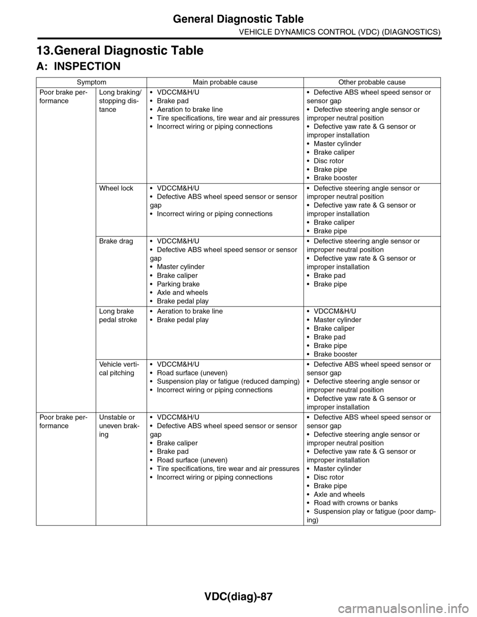
13.General Diagnostic Table
A: INSPECTION
Symptom Main probable cause Other probable cause
Po or b rake pe r -
for mance
Long braking/
stopping dis-
tance
•VDCCM&H/U
•Brake pad
•Aeration to brake line
•Tire specifications, tire wear and air pressures
•Incorrect wiring or piping connections
•Defective ABS wheel speed sensor or
sensor gap
•Defective steering angle sensor or
improper neutral position
•Defective yaw rate & G sensor or
improper installation
•Master cylinder
•Brake caliper
•Disc rotor
•Brake pipe
•Brake booster
Wheel lock • VDCCM&H/U
•Defective ABS wheel speed sensor or sensor
gap
•Incorrect wiring or piping connections
•Defective steering angle sensor or
improper neutral position
•Defective yaw rate & G sensor or
improper installation
•Brake caliper
•Brake pipe
Brake drag • VDCCM&H/U
•Defective ABS wheel speed sensor or sensor
gap
•Master cylinder
•Brake caliper
•Parking brake
•Axle and wheels
•Brake pedal play
•Defective steering angle sensor or
improper neutral position
•Defective yaw rate & G sensor or
improper installation
•Brake pad
•Brake pipe
Long brake
pedal stroke
•Aeration to brake line
•Brake pedal play
•VDCCM&H/U
•Master cylinder
•Brake caliper
•Brake pad
•Brake pipe
•Brake booster
Ve h i c l e v e r t i -
cal pitching
•VDCCM&H/U
•Road surface (uneven)
•Suspension play or fatigue (reduced damping)
•Incorrect wiring or piping connections
•Defective ABS wheel speed sensor or
sensor gap
•Defective steering angle sensor or
improper neutral position
•Defective yaw rate & G sensor or
improper installation
Po or b rake pe r -
for mance
Unstable or
uneven brak-
ing
•VDCCM&H/U
•Defective ABS wheel speed sensor or sensor
gap
•Brake caliper
•Brake pad
•Road surface (uneven)
•Tire specifications, tire wear and air pressures
•Incorrect wiring or piping connections
•Defective ABS wheel speed sensor or
sensor gap
•Defective steering angle sensor or
improper neutral position
•Defective yaw rate & G sensor or
improper installation
•Master cylinder
•Disc rotor
•Brake pipe
•Axle and wheels
•Road with crowns or banks
•Suspension play or fatigue (poor damp-
ing)
Page 1080 of 2453
VDC(diag)-88
General Diagnostic Table
VEHICLE DYNAMICS CONTROL (VDC) (DIAGNOSTICS)
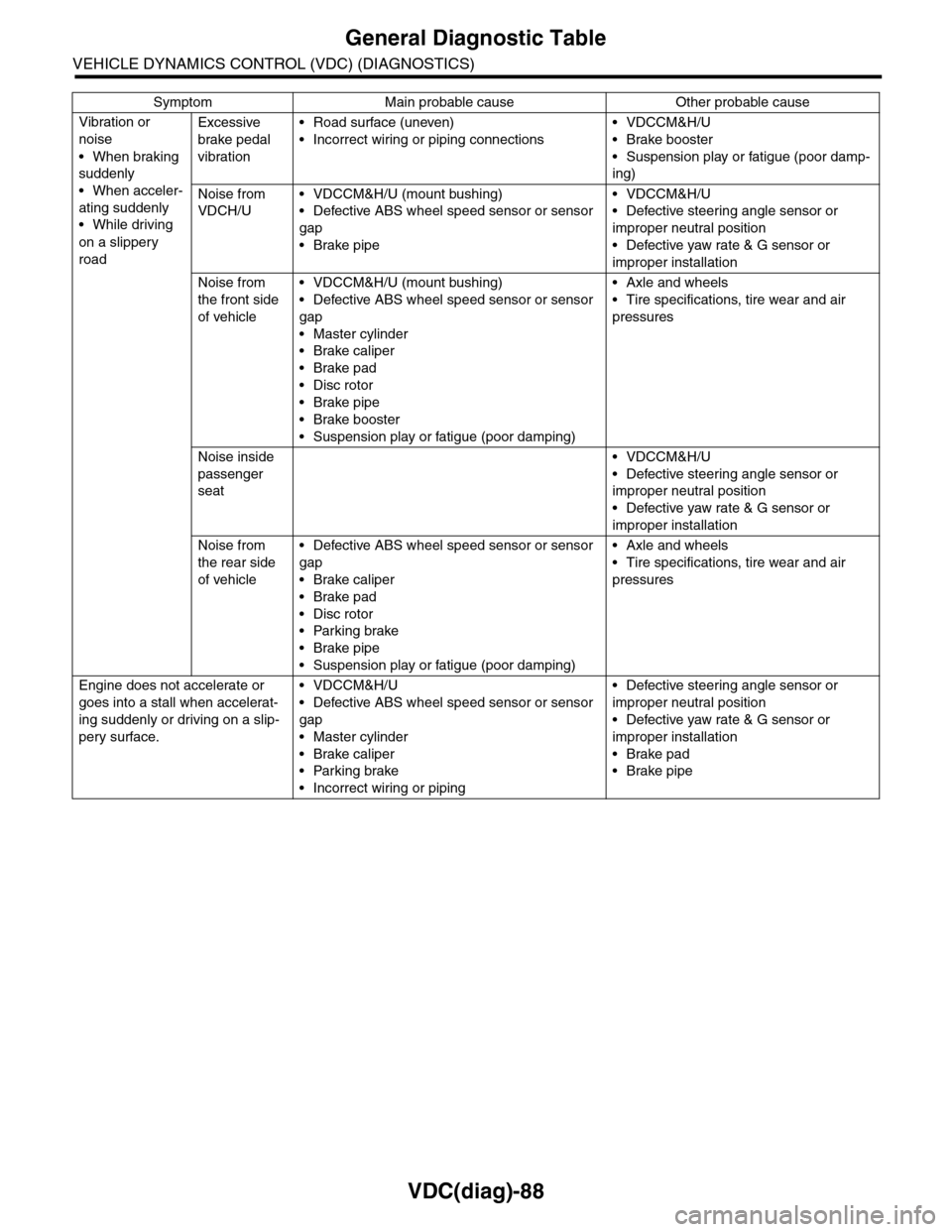
Vibration or
noise
•When braking
suddenly
•When acceler-
ating suddenly
•While driving
on a slippery
road
Excessive
brake pedal
vibration
•Road surface (uneven)
•Incorrect wiring or piping connections
•VDCCM&H/U
•Brake booster
•Suspension play or fatigue (poor damp-
ing)
Noise from
VDCH/U
•VDCCM&H/U (mount bushing)
•Defective ABS wheel speed sensor or sensor
gap
•Brake pipe
•VDCCM&H/U
•Defective steering angle sensor or
improper neutral position
•Defective yaw rate & G sensor or
improper installation
Noise from
the front side
of vehicle
•VDCCM&H/U (mount bushing)
•Defective ABS wheel speed sensor or sensor
gap
•Master cylinder
•Brake caliper
•Brake pad
•Disc rotor
•Brake pipe
•Brake booster
•Suspension play or fatigue (poor damping)
•Axle and wheels
•Tire specifications, tire wear and air
pressures
Noise inside
passenger
seat
•VDCCM&H/U
•Defective steering angle sensor or
improper neutral position
•Defective yaw rate & G sensor or
improper installation
Noise from
the rear side
of vehicle
•Defective ABS wheel speed sensor or sensor
gap
•Brake caliper
•Brake pad
•Disc rotor
•Parking brake
•Brake pipe
•Suspension play or fatigue (poor damping)
•Axle and wheels
•Tire specifications, tire wear and air
pressures
Engine does not accelerate or
goes into a stall when accelerat-
ing suddenly or driving on a slip-
pery surface.
•VDCCM&H/U
•Defective ABS wheel speed sensor or sensor
gap
•Master cylinder
•Brake caliper
•Parking brake
•Incorrect wiring or piping
•Defective steering angle sensor or
improper neutral position
•Defective yaw rate & G sensor or
improper installation
•Brake pad
•Brake pipe
Symptom Main probable cause Other probable cause
Page 1113 of 2453
WT-7
Aluminum Wheel
WHEEL AND TIRE SYSTEM
3. Aluminum Wheel
A: REMOVAL
1) Apply the parking brake, and position select le-
ver to “P” or “LOW”.
2) Set the shop jacks or a lift to the specified points,
and support the vehicle with its wheels slightly con-
tacting the floor.
3) Loosen the wheel nuts.
4) Raise the vehicle until its wheels are off the
ground using the jack or a lift.
5) Remove the wheel nuts and wheels.
NOTE:
•When removing the wheels, be careful not to
damage the hub bolts.
•Place the wheels with their outer sides facing up-
ward to prevent wheels from being damaged.
B: INSTALLATION
1) Remove dirt from the mating surface of the
wheel and brake rotor.
2) Attach the wheel to the hub by aligning the wheel
bolt holes with the hub bolts.
3) Temporarily attach the wheel nuts to the hub
bolts. (In the case of aluminum wheels, use SUBA-
RU genuine wheel nuts for aluminum wheels.)
4) Tighten the nuts by hand, making sure the wheel
hub hole is aligned correctly to the guide portion of
hub.
5) Tighten the wheel nuts in a diagonal selection to
the specified torque. Use a wheel nut wrench.
Wheel nut tightening torque:
110 N·m (11.2 kgf-m, 81.1 ft-lb)
CAUTION:
•Tighten the wheel nuts in two or three steps
by gradually increasing the torque on opposing
nuts, until they reach the specified torque.
•Do not push the wrench by foot. Always use
both hands when tightening the nuts.
•Make sure the bolt, nut and the nut seating
surface of the wheel are free from oil.
6) If a wheel is removed for replacement or for re-
pair of a puncture, retighten the wheel nuts to the
specified torque after driving 1,000 km (600 miles).
C: INSPECTION
1) Deformation or damage to the rim may cause air
leakage. Check the rim flange for deformation,
cracks or damage, and repair or replace as neces-
sary.
2) Jack-up the vehicle until wheels clear the floor.
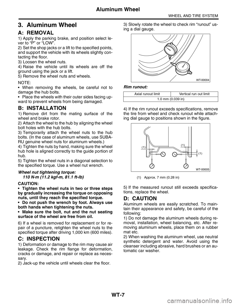
3) Slowly rotate the wheel to check rim “runout” us-
ing a dial gauge.
Rim runout:
4) If the rim runout exceeds specifications, remove
the tire from wheel and check runout while attach-
ing dial gauge to positions shown in the figure.
5) If the measured runout still exceeds specifica-
tions, replace the wheel.
D: CAUTION
Aluminum wheels are easily scratched. To main-
tain their appearance and safety, be careful of the
following:
1) Do not damage the aluminum wheels during re-
moval, installation, wheel balancing, etc. After re-
moving aluminum wheels, place them on a rubber
mat etc.
2) When washing the aluminum wheel, use neutral
synthetic detergent and water. Avoid using the
cleanser including abrasive, hard brushes or an au-
tomatic car washer.
Axial runout limit Vertical run out limit
1.0 mm (0.039 in)
(1) Approx. 7 mm (0.28 in)
WT-00004
WT-00005
(1)
(1)
(1)
Page 1198 of 2453
EN(H6DO)(diag)-37
Inspection Mode
ENGINE (DIAGNOSTICS)
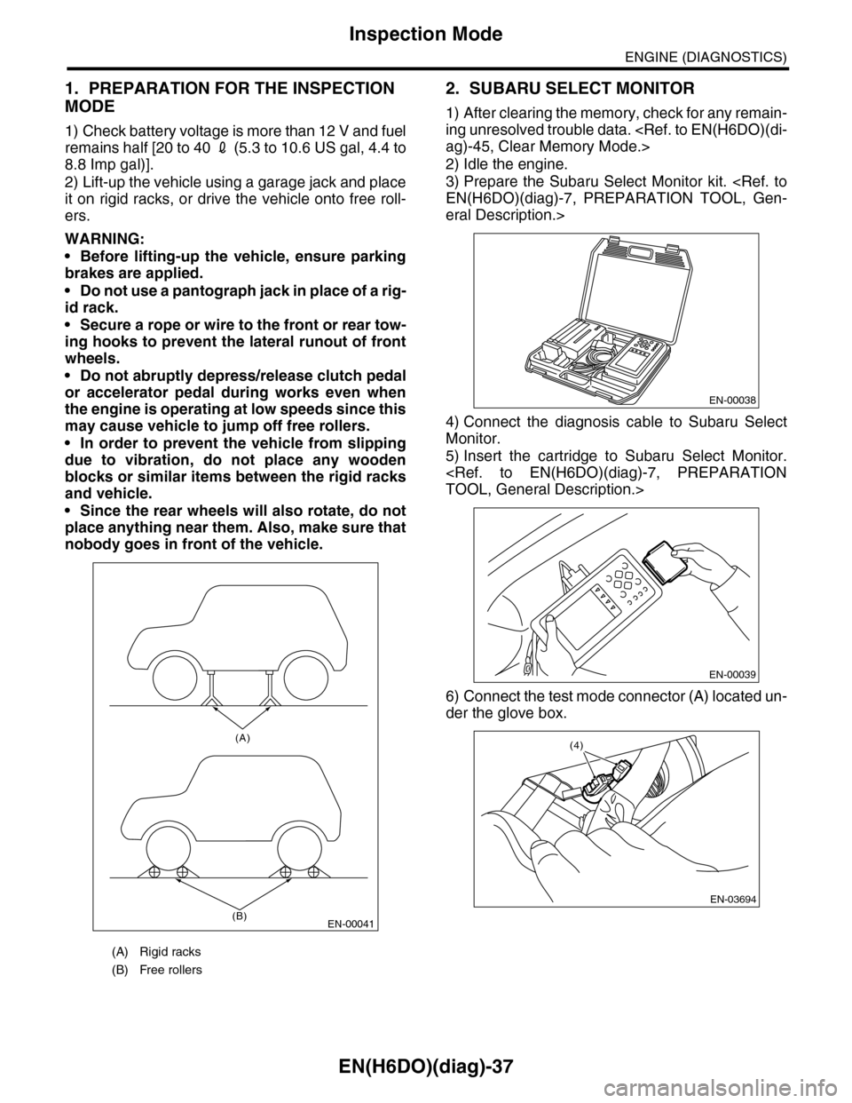
1. PREPARATION FOR THE INSPECTION
MODE
1) Check battery voltage is more than 12 V and fuel
remains half [20 to 40 2 (5.3 to 10.6 US gal, 4.4 to
8.8 Imp gal)].
2) Lift-up the vehicle using a garage jack and place
it on rigid racks, or drive the vehicle onto free roll-
ers.
WARNING:
•Before lifting-up the vehicle, ensure parking
brakes are applied.
•Do not use a pantograph jack in place of a rig-
id rack.
•Secure a rope or wire to the front or rear tow-
ing hooks to prevent the lateral runout of front
wheels.
•Do not abruptly depress/release clutch pedal
or accelerator pedal during works even when
the engine is operating at low speeds since this
may cause vehicle to jump off free rollers.
•In order to prevent the vehicle from slipping
due to vibration, do not place any wooden
blocks or similar items between the rigid racks
and vehicle.
•Since the rear wheels will also rotate, do not
place anything near them. Also, make sure that
nobody goes in front of the vehicle.
2. SUBARU SELECT MONITOR
1) After clearing the memory, check for any remain-
ing unresolved trouble data.
2) Idle the engine.
3) Prepare the Subaru Select Monitor kit.
eral Description.>
4) Connect the diagnosis cable to Subaru Select
Monitor.
5) Insert the cartridge to Subaru Select Monitor.
6) Connect the test mode connector (A) located un-
der the glove box.
(A) Rigid racks
(B) Free rollers
EN-00041
(A)
(B)
EN-00038
EN-00039
EN-03694
(4)