Page 1621 of 2453
GD(H6DO)-9
Diagnostic Trouble Code (DTC) Detecting Criteria
GENERAL DESCRIPTION
2. Diagnostic Trouble Code (DTC) Detecting Criteria
A: DTC P0011 INTAKE CAMSHAFT POSITION TIMING - OVER-ADVANCED
(BANK 1)
1. OUTLINE OF DIAGNOSIS
Detect the AVCS system malfunction.
There are two types of diagnosis: Crankshaft cam timing diagnosis; and slow response diagnosis. Either of
these is performed according to the status of the engine while running.
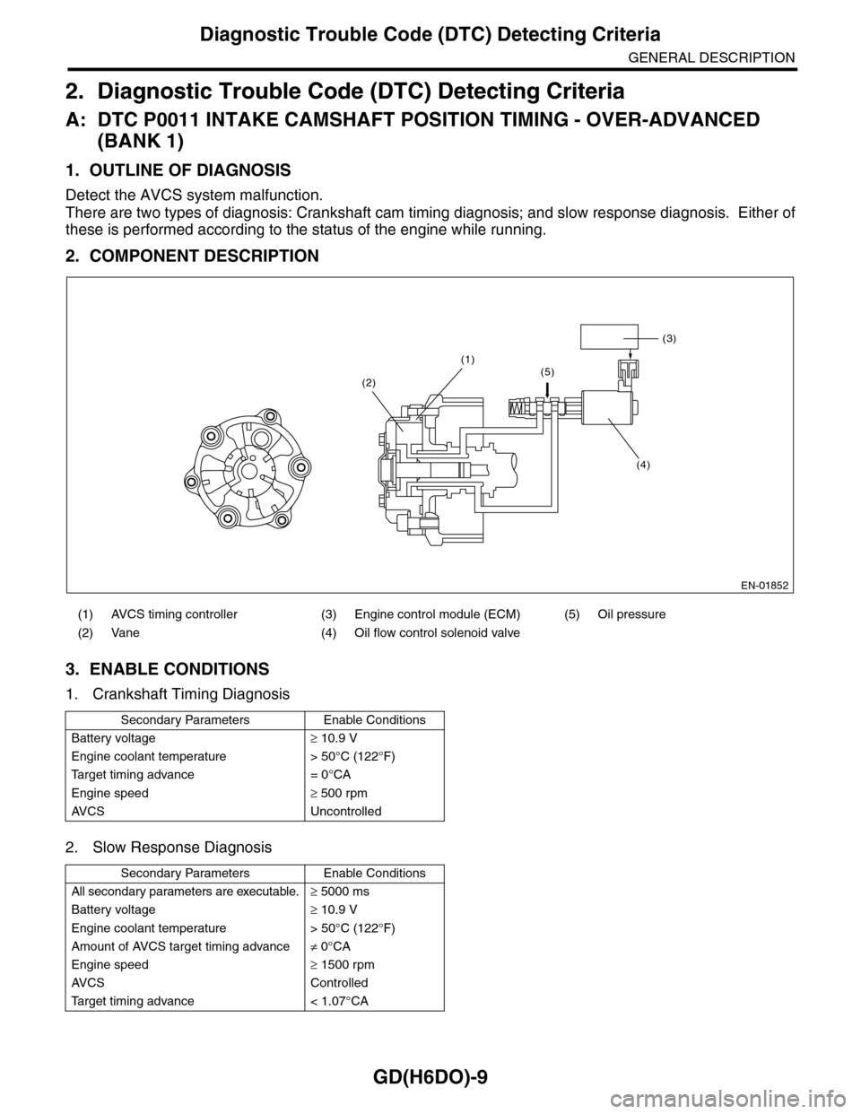
2. COMPONENT DESCRIPTION
3. ENABLE CONDITIONS
1. Crankshaft Timing Diagnosis
2. Slow Response Diagnosis
(1) AVCS timing controller (3) Engine control module (ECM) (5) Oil pressure
(2) Vane (4) Oil flow control solenoid valve
Secondary Parameters Enable Conditions
Battery voltage≥ 10.9 V
Engine coolant temperature > 50°C (122°F)
Ta r g e t t i m i n g a d v a n c e = 0 ° C A
Engine speed≥ 500 rpm
AV C S U n c o n t r o l l e d
Secondary Parameters Enable Conditions
All secondary parameters are executable.≥ 5000 ms
Battery voltage≥ 10.9 V
Engine coolant temperature > 50°C (122°F)
Amount of AVCS target timing advance≠ 0°CA
Engine speed≥ 1500 rpm
AV C S C o n t r o l l e d
Ta r g e t t i m i n g a d v a n c e < 1 . 0 7 ° C A
EN-01852
(3)
(4)
(1)(5)(2)
Page 1625 of 2453
GD(H6DO)-13
Diagnostic Trouble Code (DTC) Detecting Criteria
GENERAL DESCRIPTION
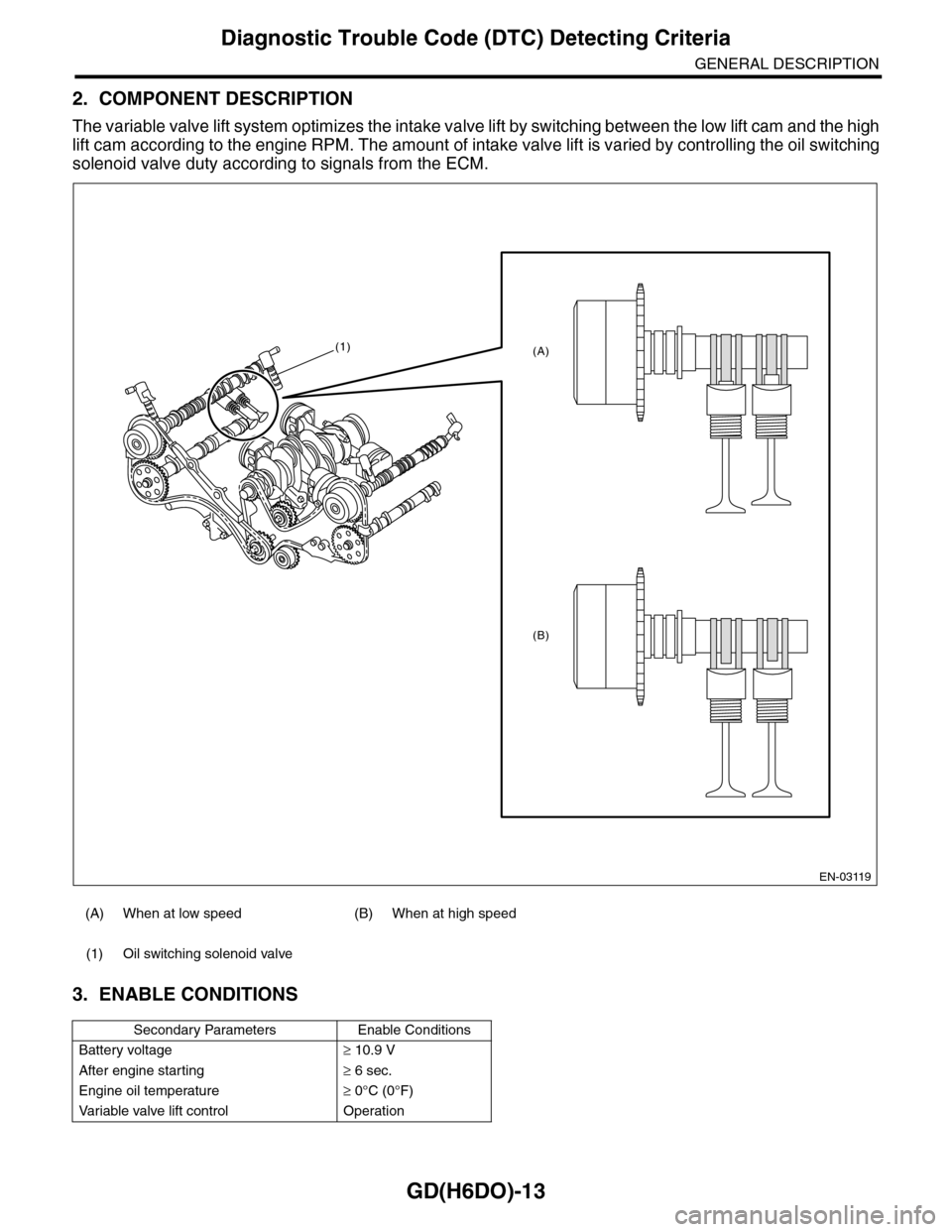
2. COMPONENT DESCRIPTION
The variable valve lift system optimizes the intake valve lift by switching between the low lift cam and the high
lift cam according to the engine RPM. The amount of intake valve lift is varied by controlling the oil switching
solenoid valve duty according to signals from the ECM.
3. ENABLE CONDITIONS
(A) When at low speed (B) When at high speed
(1) Oil switching solenoid valve
Secondary Parameters Enable Conditions
Battery voltage≥ 10.9 V
After engine starting≥ 6 sec.
Engine oil temperature≥ 0°C (0°F)
Va r i a b l e va l v e l i f t c o n t r o l O p e r a t i o n
EN-03119
(1)
(B)
(A)
Page 1706 of 2453
GD(H6DO)-94
Diagnostic Trouble Code (DTC) Detecting Criteria
GENERAL DESCRIPTION
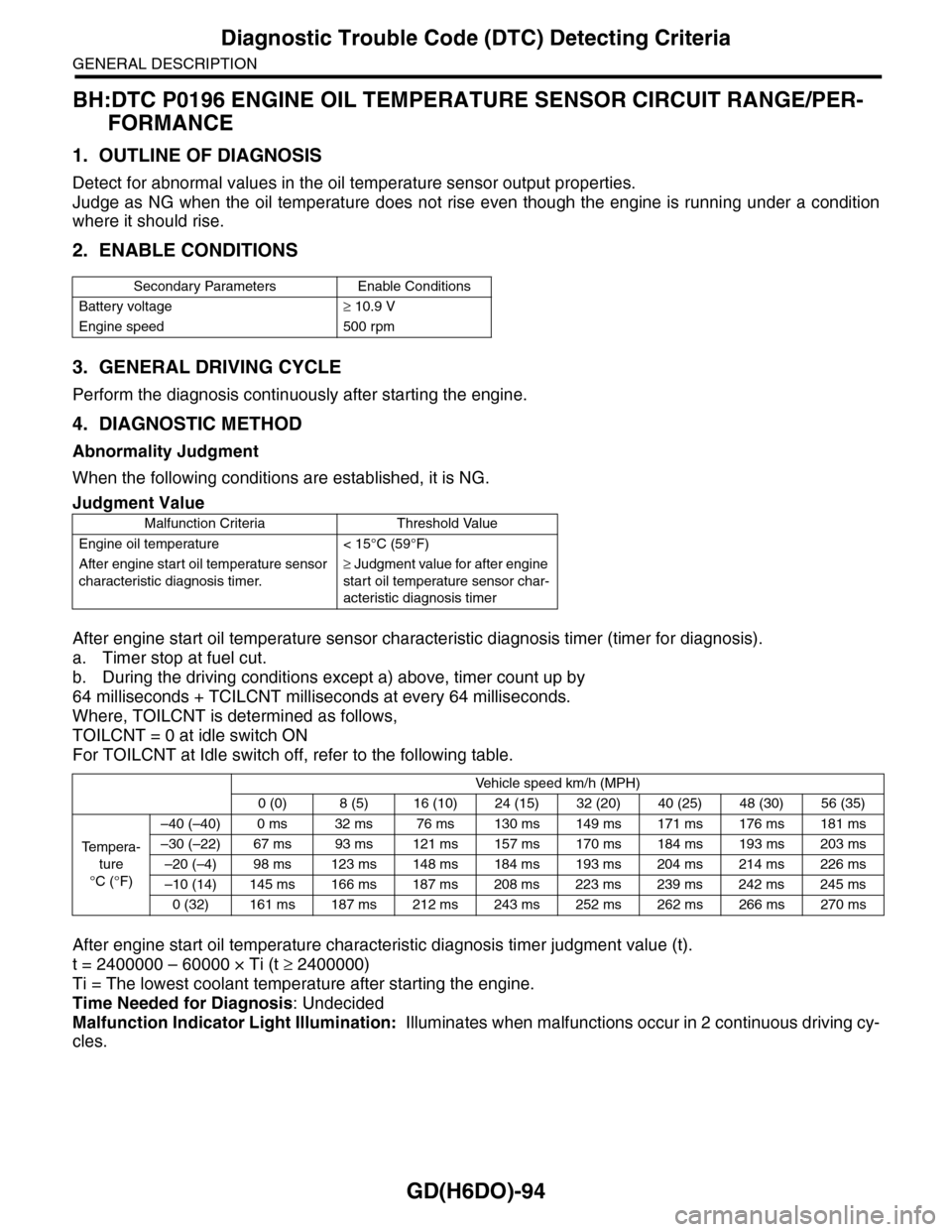
BH:DTC P0196 ENGINE OIL TEMPERATURE SENSOR CIRCUIT RANGE/PER-
FORMANCE
1. OUTLINE OF DIAGNOSIS
Detect for abnormal values in the oil temperature sensor output properties.
Judge as NG when the oil temperature does not rise even though the engine is running under a condition
where it should rise.
2. ENABLE CONDITIONS
3. GENERAL DRIVING CYCLE
Perform the diagnosis continuously after starting the engine.
4. DIAGNOSTIC METHOD
Abnormality Judgment
When the following conditions are established, it is NG.
After engine start oil temperature sensor characteristic diagnosis timer (timer for diagnosis).
a. Timer stop at fuel cut.
b. During the driving conditions except a) above, timer count up by
64 milliseconds + TCILCNT milliseconds at every 64 milliseconds.
Where, TOILCNT is determined as follows,
TOILCNT = 0 at idle switch ON
For TOILCNT at Idle switch off, refer to the following table.
After engine start oil temperature characteristic diagnosis timer judgment value (t).
t = 2400000 – 60000 × Ti (t ≥ 2400000)
Ti = The lowest coolant temperature after starting the engine.
Time Needed for Diagnosis: Undecided
Malfunction Indicator Light Illumination: Illuminates when malfunctions occur in 2 continuous driving cy-
cles.
Secondary Parameters Enable Conditions
Battery voltage≥ 10.9 V
Engine speed 500 rpm
Judgment Value
Malfunction Criteria Threshold Value
Engine oil temperature < 15°C (59°F)
After engine start oil temperature sensor
characteristic diagnosis timer.
≥ Judgment value for after engine
start oil temperature sensor char-
acteristic diagnosis timer
Vehicle speed km/h (MPH)
0 (0) 8 (5) 16 (10) 24 (15) 32 (20) 40 (25) 48 (30) 56 (35)
Te m p e r a -
ture
°C (°F)
–40 (–40) 0 ms 32 ms 76 ms 130 ms 149 ms 171 ms 176 ms 181 ms
–30 (–22) 67 ms 93 ms 121 ms 157 ms 170 ms 184 ms 193 ms 203 ms
–20 (–4) 98 ms 123 ms 148 ms 184 ms 193 ms 204 ms 214 ms 226 ms
–10 (14) 145 ms 166 ms 187 ms 208 ms 223 ms 239 ms 242 ms 245 ms
0 (32) 161 ms 187 ms 212 ms 243 ms 252 ms 262 ms 266 ms 270 ms
Page 1707 of 2453
GD(H6DO)-95
Diagnostic Trouble Code (DTC) Detecting Criteria
GENERAL DESCRIPTION
Normality Judgment
When the following conditions are established, it is OK.
5. DTC CLEAR CONDITION
•When the OK idling cycle is completed 40 times in a row
•When “Clear Memory” is performed
6. MALFUNCTION INDICATOR LIGHT CLEAR CONDITIONS
•When the OK driving cycle is completed 3 times in a row
•When “Clear Memory” is performed
7. FAIL SAFE
Oil temperature sensor process: Engine oil temperature is fixed at 70°C (158°F).
8. ECM OPERATION AT DTC SETTING
Memorize the freeze frame data. (For test mode $02)
Judgment Value
Malfunction Criteria Threshold Value
Engine oil temperature≥ 15°C (59°F)
Page 1708 of 2453
GD(H6DO)-96
Diagnostic Trouble Code (DTC) Detecting Criteria
GENERAL DESCRIPTION
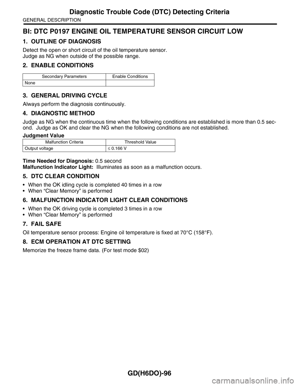
BI: DTC P0197 ENGINE OIL TEMPERATURE SENSOR CIRCUIT LOW
1. OUTLINE OF DIAGNOSIS
Detect the open or short circuit of the oil temperature sensor.
Judge as NG when outside of the possible range.
2. ENABLE CONDITIONS
3. GENERAL DRIVING CYCLE
Always perform the diagnosis continuously.
4. DIAGNOSTIC METHOD
Judge as NG when the continuous time when the following conditions are established is more than 0.5 sec-
ond. Judge as OK and clear the NG when the following conditions are not established.
Time Needed for Diagnosis: 0.5 second
Malfunction Indicator Light: Illuminates as soon as a malfunction occurs.
5. DTC CLEAR CONDITION
•When the OK idling cycle is completed 40 times in a row
•When “Clear Memory” is performed
6. MALFUNCTION INDICATOR LIGHT CLEAR CONDITIONS
•When the OK driving cycle is completed 3 times in a row
•When “Clear Memory” is performed
7. FAIL SAFE
Oil temperature sensor process: Engine oil temperature is fixed at 70°C (158°F).
8. ECM OPERATION AT DTC SETTING
Memorize the freeze frame data. (For test mode $02)
Secondary Parameters Enable Conditions
None
Judgment Value
Malfunction Criteria Threshold Value
Output voltage≤ 0.166 V
Page 1709 of 2453
GD(H6DO)-97
Diagnostic Trouble Code (DTC) Detecting Criteria
GENERAL DESCRIPTION
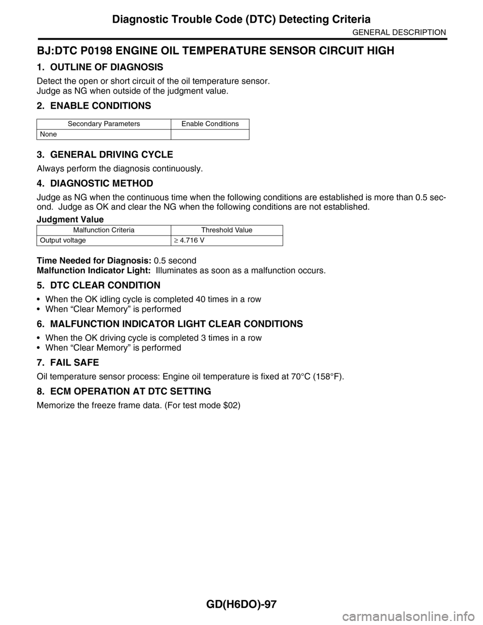
BJ:DTC P0198 ENGINE OIL TEMPERATURE SENSOR CIRCUIT HIGH
1. OUTLINE OF DIAGNOSIS
Detect the open or short circuit of the oil temperature sensor.
Judge as NG when outside of the judgment value.
2. ENABLE CONDITIONS
3. GENERAL DRIVING CYCLE
Always perform the diagnosis continuously.
4. DIAGNOSTIC METHOD
Judge as NG when the continuous time when the following conditions are established is more than 0.5 sec-
ond. Judge as OK and clear the NG when the following conditions are not established.
Time Needed for Diagnosis: 0.5 second
Malfunction Indicator Light: Illuminates as soon as a malfunction occurs.
5. DTC CLEAR CONDITION
•When the OK idling cycle is completed 40 times in a row
•When “Clear Memory” is performed
6. MALFUNCTION INDICATOR LIGHT CLEAR CONDITIONS
•When the OK driving cycle is completed 3 times in a row
•When “Clear Memory” is performed
7. FAIL SAFE
Oil temperature sensor process: Engine oil temperature is fixed at 70°C (158°F).
8. ECM OPERATION AT DTC SETTING
Memorize the freeze frame data. (For test mode $02)
Secondary Parameters Enable Conditions
None
Judgment Value
Malfunction Criteria Threshold Value
Output voltage≥ 4.716 V
Page 1851 of 2453
LU(H6DO)-2
General Description
LUBRICATION
1. General Description
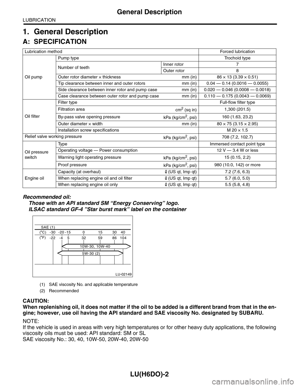
A: SPECIFICATION
Recommended oil:
Those with an API standard SM “Energy Conserving” logo.
ILSAC standard GF-4 ”Star burst mark” label on the container
CAUTION:
When replenishing oil, it does not matter if the oil to be added is a different brand from that in the en-
gine; however, use oil having the API standard and SAE viscosity No. designated by SUBARU.
NOTE:
If the vehicle is used in areas with very high temperatures or for other heavy duty applications, the following
viscosity oils must be used: API standard: SM or SL
SAE viscosity No.: 30, 40, 10W-50, 20W-40, 20W-50
Lubrication methodForced lubr ication
Oil pump
Pump typeTr o c h o i d t y p e
Number of teethInner rotor 7
Outer rotor 8
Outer rotor diameter × thickness mm (in) 86 × 13 (3.39 × 0.51)
Tip clearance between inner and outer rotors mm (in) 0.04 — 0.14 (0.0016 — 0.0055)
Side clearance between inner rotor and pump case mm (in) 0.020 — 0.046 (0.0008 — 0.0018)
Case clearance between outer rotor and pump case mm (in) 0.110 — 0.175 (0.0043 — 0.0069)
Oil filter
Filter typeFull-flow filter type
Filtration areacm2 (sq in)1,300 (201.5)
By-pass valve opening pressurekPa (kg/cm2, psi)160 (1.63, 23.2)
Outer diameter × width mm (in) 80 × 75 (3.15 × 2.95)
Installation screw specifications M 20 × 1.5
Relief valve working pressurekPa (kg/cm2, psi)708 (7.2, 102.7)
Oil pressure
switch
Ty p eImmersed contact point type
Operating voltage — Power consumption 12 V — 3.4 W or less
Wa r ni n g l ig h t o p era t i ng pr e ss ur ekPa (kg/cm2, psi)15 (0.15, 2.2)
Proof pressurekPa (kg/cm2, psi)980 (10.0, 142) or more
Engine oil
Capacity (at overhaul)2(US qt, Imp qt) 7.2 (7.6, 6.3)
When replacing engine oil and oil filter2(US qt, Imp qt) 5.7 (6.0, 5.0)
When replacing engine oil only2(US qt, Imp qt) 5.5 (5.8, 4.8)
(1) SAE viscosity No. and applicable temperature
(2) Recommended
LU-02149
( C) -30 -20 -15 0 15 30 40
-22 -4 5 32 59 86 104
SAE (1)
( F)
5W-30 (2)
10W-30, 10W-40
Page 1891 of 2453
ME(H6DO)-25
Engine Oil Pressure
MECHANICAL
6. Engine Oil Pressure
A: INSPECTION
1) Remove the oil pressure switch from cylinder
block.
Pressure Switch.>
2) Connect the oil pressure gauge hose to cylinder
block.
3) Connect the ground cable to the battery.
4) Start the engine, and measure the oil pressure.
OIL PRESSURE (at oil temperature of 80°C
(176°F)):
Standard:
135 kPa (1.4 kgf/cm2, 20 psi) or more (at
600 rpm)
500 kPa (5.1 kgf/cm2, 73 psi) or more (at
5,000 rpm)
CAUTION:
•If the oil pressure is out of specification,
check oil pump, oil filter and lubrication line.
Diagnostics Table.>
•If the oil pressure warning light is turned ON
and oil pressure is in specification, replace the
oil pressure switch.
SPECTION, General Diagnostics Table.>
5) After measuring the oil pressure, install the oil
pressure switch.
LATION, Oil Pressure Switch.>
Tightening torque:
25 N·m (2.5 kgf-m, 18 ft-lb)