2009 SUBARU TRIBECA oil temperature
[x] Cancel search: oil temperaturePage 788 of 2453

DI-4
General Description
DIFFERENTIALS
B: COMPONENT
1. REAR DIFFERENTIAL (VA2-TYPE)
(1) Hypoid driven gear and drive pin-
ion set
(13) Lock plate (26) Clip
(14) Side bearing (27) Stay ground
(2) Pinion height adjusting washer (15) O–ring (28)
Rear differential oil temperature
switch(3) Rear bearing (16) Axle shaft holder
(4) Bearing preload adjusting collar (17) Side oil seal
(5) Bearing preload adjusting washer (18) Differential case ASSYTightening torque: N·m (kgf-m, ft-lb)
(6) Differential carrier (19) Air breather hoseT1: 25 (2.5, 18.1)
(7) Front bearing (20) Stud boltT2: 29 (3.0, 21.4)
(8) Collar (21) GasketT3: 34 (3.5, 25.3)
(9) Pilot bearing (22) Oil filler plugT4: 60 (6.1, 44.3)
(10) Front oil seal (23) Oil drain plugT5: 62 (6.3, 45.6)
(11) Companion flange (24) Rear coverT6: 191 (19.5, 141)
(12) Self–locking nut (25) Gasket
Page 798 of 2453

DI-14
Rear Differential (VA–type)
DIFFERENTIALS
4. Rear Differential (VA–type)
A: REMOVAL
1) Disconnect the ground cable from the battery.
2) Release the parking brake.
3) Jack-up the vehicle.
4) Remove the rear exhaust pipe and muffler.
5) Remove the heat shield cover.
6) Remove the propeller shaft.
7) Remove the connector from the rear differential
oil temperature switch.
8) Prepare the transmission jack and band.
9) Remove the DOJ of rear drive shaft from rear dif-
ferential.
10) Remove the nuts which hold the rear differen-
tial front member.
11) Support the rear differential with the transmis-
sion jack.
12) Loosen the self-lock nuts which hold the rear
differential to rear crossmember.
AT-03243
DI-00471
DI-00268
(A) Tire lever
(B) Bolt
DI-00472
(A)
(B)
DI-00358
DI-00473
DI-00269
Page 801 of 2453

DI-17
Rear Differential (VA–type)
DIFFERENTIALS
12) Tighten the self-locking nut.
Tightening torque:
70 N·m (7.1 kgf-m, 51 ft-lb)
13) Lower the transmission jack.
14) Install the air breather hose to the sub frame.
15) Install the propeller shaft.
16) Install the heat shield cover.
17) Install the rear exhaust pipe and muffler.
C: DISASSEMBLY
To detect the real cause of trouble, inspect the fol-
lowing items before disassembling.
•Tooth contact and backlash between hypoid driv-
en gear and drive pinion
•Total preload of drive pinion
1) Remove the air breather hose.
2) Set the ST on vise and install the differential as-
sembly to ST.
ST 398217700 ATTACHMENT SET
3) Drain the gear oil by removing the plug.
4) Remove the rear differential oil temperature
switch.
5) Remove the rear cover by loosening retaining
bolts.
6) Remove the lock plate RH and LH.
7) Remove the holder RH and LH with ST.
ST 18630AA010 WRENCH ASSY
8) Pull out the differential case assembly from dif-
ferential carrier.
NOTE:
Be careful so that the teeth do not to hit against the
case.
DI-00269
STDI-00363
DI-00388
DI-00364
ST
DI-00365
DI-00366
Page 811 of 2453

DI-27
Rear Differential (VA–type)
DIFFERENTIALS
•Flank contact
Check item: Backlash is too small.
Contact pattern
Corrective action: Reduce the thickness of pinion
height adjusting washer according to the procedure for
bringing drive pinion away from hypoid driven gear.
•Toe contact (inner side contact)
Check item: Teeth contact area is too small.
Contact pattern
Corrective action: Reduce the thickness of pinion
height adjusting washer according to the procedure
for bringing drive pinion away from hypoid driven gear.
•Heel contact (outside end contact)
Check item: Teeth contact area is too small.
Contact pattern
Corrective action: Increase thickness of drive pin-
ion height adjusting washer in order to bring drive
pinion close to hypoid driven gear.
20) If proper tooth contact is not obtained, once
again adjust the drive pinion height and the differ-
ential side bearing preload (already mentioned)
and the hypoid gear backlash.
21) Attach a new gasket, rear cover, and ground
stay to the differential carrier.
Tightening torque:
34 N·m (3.5 kgf-m, 25.1 ft-lb)
22) Using new gaskets, install the rear differential
oil temperature switch.
Tightening torque:
60 N·m (6.1 kgf-m, 44.3 ft-lb)
AT-00209
AT-00213
AT-00210
AT-00213
AT-00211
AT-00212
DI-00477
Page 919 of 2453

PS-39
Pipe Assembly
POWER ASSISTED SYSTEM (POWER STEERING)
C: INSPECTION
Check all disassembled parts for wear, damage or other problems. Repair or replace the defective parts as
necessary.
CAUTION:
Although the surface layer materials of rubber hoses have excellent weathering resistance, heat re-
sistance and resistance for low temperature brittleness, they are likely to be damaged chemically by
brake fluid, battery electrolyte, engine oil and automatic transmission fluid and their service lives are
to be very shortened. Wipe off hoses immediately if any of these come into contact with the hoses.
Since resistances for heat or low temperature brittleness are gradually declining according to time
accumulation of hot or cold conditions for the hoses and their service lives are shortening accord-
ingly, it is necessary to perform careful inspection frequently when the vehicle is used in hot weather
areas, cold weather areas and a driving condition in which many steering operations are required in
short time.
Particularly continuous work of relief valve over 5 seconds causes to reduce service lives of the hos-
es, the oil pump, the fluid, etc. due to over heat.
Par t Maintenance par ts Corrective action
Pipe
•O–ring fitting surface damage
•Nut damage
•Pipe damage
Replace with a new part.
Clamp • Loose clamps Replace with a new part.
Hose
•Flare surface damage
•Flare nut damage
•Outer surface cracks
•Outer surface wear
•Clip damage
•End coupling or adapter for deformation
Replace with a new part.
Tr o u b l e P o s s i b l e c a u s e C o r r e c t i v e a c t i o n
Pressure hose burst
Excessive holding time of relief status Instruct customers.
Malfunction of the relief valve Replace the oil pump.
Poor cold character istic of fluid R eplace fluid.
Disconnection of the return
hose
Improper connection Repair.
Loosening of the clip Retighten.
Poor cold character istic of fluid R eplace fluid.
Fluid slightly leaking out of
hose
Wrong layout, tensioned Replace the hose.
Excessive play of engine due to deterioration of
engine mounting rubberReplace the parts if defective.
Improper stop position of pitching stopper Replace the parts if defective.
Crack on hose
Excessive holding time of relief statusReplace.
Instruct customers.
Excessive tightening torque for return hose clip Replace.
Power steer ing fluid, engine oil, electrolyte adhere
on the hose surface
Replace.
Be careful during service work.
To o m a n y u s e s i n e x t r e m e l y c o l d w e a t h e rReplace.
Instruct customers.
Page 928 of 2453

PS-48
Power Steering Fluid
POWER ASSISTED SYSTEM (POWER STEERING)
9. Power Steering Fluid
A: SPECIFICATION
B: INSPECTION
1) Check the power steering fluid for deterioration
or contamination. If the fluid is highly deteriorated
or contaminated, drain it and refill with new fluid.
2) Check the joints and units for oil leakage. If any
oil leaks are found, repair or replace the applicable
part.
3) Inspect the fluid level of reservoir tank with vehi-
cle on level surface and engine stopped.
If the level is at “MIN. ” point or below, add fluid to
keep the level in the specified range of the indica-
tor. If at “MAX. ” point or above, drain fluid by using
a syringe or the like.
(1) Check at power steering fluid temperature
20°C (68°F); read the fluid level on the “COLD”
side.
(2) Check at power steering fluid temperature
80°C (176°F); read the fluid level on the “HOT”
side.
C: REPLACEMENT
1) Lift-up the vehicle.
2) Remove the crossmember support.
3) Remove the pipe joint in the center of gearbox,
and connect the vinyl hose to the pipe and joint.
Wipe fluid off while turning the steering wheel.
4) Add the specified fluid to reservoir tank at “MAX”
level.
5) Continue to turn the steering wheel slowly from
lock to lock until the bubbles stop appearing on oil
surface while keeping the fluid at the level in the
Step 4).
6) If the steering wheel is turned in a low fluid level
condition, air will be sucked into the pipe. If sucked,
leave it about half an hour and then do the step 5)
again.
7) Start the engine and let it idle.
8) Continue to turn the steering wheel slowly from
lock to lock again until the bubbles stop appearing
on oil surface while keeping the fluid at the level in
Step 4).
Normally bubbles will stop appearing after turning
the steering wheel from lock to lock three times.
9) In case bubbles do not stop appearing in the
tank, leave it about half an hour and then do the
step 4) all over again.
10) Lower the vehicle, and then idle the engine.
11) Continue to turn the steering wheel from lock to
lock until the bubbles stop appearing and change of
the fluid level is within 3 mm (0.12 in).
12) In case the following happens, leave it about
half an hour and then do step 8) to 11) again.
(1) The fluid level changes over 3 mm (0.12 in).
(2) Bubbles remain on the upper surface of the
fluid.
(3) Grinding noise is generated from oil pump.
13) Check the fluid leakage after turning steering
wheel from lock to lock with engine running.
Recommended power steering fluid Manufacturer
AT F D E X R O N I I I o r e q u i v a l e n t
B.P.
CALTEX
CASTROL
MOBIL
SHELL
TEXACO
PS-00745
HOT MAXHOT MAINCOLD MAXCOLD MAIN
Page 930 of 2453

PS-50
General Diagnostic Table
POWER ASSISTED SYSTEM (POWER STEERING)
1. NOISE & VIBRATION
CAUTION:
Do not keep the relief valve operated over five seconds at any time or inner parts of the oil pump may
be damaged due to rapid increase of fluid temperature.
NOTE:
•A screeching noise may be heard immediately after the engine start in extremely cold conditions. In this
case, if the noise goes off during warm-up there is no abnormal function in the system. This is due to the fluid
characteristics in extremely cold condition.
•The oil pump normally makes a small whining noise due to its mechanism. Even if a noise is heard when
steering wheel is turned at stand still, there is no abnormal function in the system provided that the noise
eliminates when the vehicle is driving.
•When turning the steering wheel with the brake applied when the vehicle is parked, a screeching noise
may be generated by the brake disc and pads. This is not a fault in the steering system.
•There may be a small vibration around the steering devices when turning the steering wheel at standstill,
even though the component parts are operating properly.
Hydraulic systems are likely to generate this kind of vibration as well as working noise and fluid noise be-
cause of combined conditions, i.e., road surface and tire surface, engine speed and turning speed of steering
wheel, fluid temperature and braking condition.
These conditions do not indicate a problem in the system.
Confirm vibration for an AT model, by applying the parking brake on a concrete surface, shifting into the “D”
range, and turning the steering wheel repeatedly from slow to rapid, step by step.
Tr o u b l e P o s s i b l e c a u s e C o r r e c t i v e a c t i o n
Hiss noise (continuous)
While engine is running.
Relief valve emits operating sound when steering wheel is
completely turned in either direction. (Do not keep this
condition over five seconds.)
Normal
Relief valve emits operating sound when steering wheel is
not turned. This means that the relief valve is defective. Replace the oil pump.
Rattling noise (intermittent)
While engine is running.
Interference with adjacent parts
Check the clearance.
Correct if necessary.
Loosened installation of oil pump, oil tank, pump bracket,
gearbox or crossmemberRetighten.
Loose oil pump pulley or other pulley(s) Retighten.
Looseness of linkage, play of steering, improper tightening
(looseness) of suspension joint or steering columnRetighten or replace.
Sound generates from the inside of gearbox or oil pump.Replace faulty parts in the gear-
box or oil pump.
Knocking
When turning steering wheel in
both directions with small angle
repeatedly at engine ON or OFF.
Excessive backlash
Loosened lock nut for adjusting backlashAdjust and retighten.
Insufficient tightening or play in the tie–rod or tie–rod end Retighten or replace.
Grinding noise (continuous)
While engine is running.
Air in vane pump
Inspect and retighten the fluid
line connection.
Refill the fluid and vent air.
Va n e p u m p s e i z i n g R e p l a c e t h e o i l p u m p.
Oil pump pulley bearing seized Replace the oil pump.
Folded hose, flattened pipe Replace.
Squeal, squeak (intermittent or
continuous)
While engine is running.
Improper adjustment of pulley belt
Damaged or over tensioned pulley belt
Unequal length of pulley belts
Adjust or replace.
(Replace two belts as a set.)
Runout or dirty V–groove surface of oil pump pulley Clean or replace.
Page 1127 of 2453
CO(H6DO)-8
Radiator Fan System
COOLING
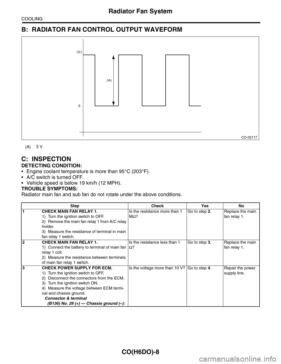
B: RADIATOR FAN CONTROL OUTPUT WAVEFORM
C: INSPECTION
DETECTING CONDITION:
•Engine coolant temperature is more than 95°C (203°F).
•A/C switch is turned OFF.
•Vehicle speed is below 19 km/h (12 MPH).
TROUBLE SYMPTOMS:
Radiator main fan and sub fan do not rotate under the above conditions.
(A) 5 V
Step Check Yes No
1CHECK MAIN FAN RELAY 1.
1) Turn the ignition switch to OFF.
2) Remove the main fan relay 1 from A/C relay
holder.
3) Measure the resistance of terminal in main
fan relay 1 switch.
Is the resistance more than 1
MΩ?
Go to step 2.Replace the main
fan relay 1.
2CHECK MAIN FAN RELAY 1.
1) Connect the battery to terminal of main fan
relay 1 coil.
2) Measure the resistance between terminals
of main fan relay 1 switch.
Is the resistance less than 1
Ω?
Go to step 3.Replace the main
fan relay 1.
3CHECK POWER SUPPLY FOR ECM.
1) Turn the ignition switch to OFF.
2) Disconnect the connectors from the ECM.
3) Turn the ignition switch ON.
4) Measure the voltage between ECM termi-
nal and chassis ground.
Connector & terminal
(B136) No. 29 (+) — Chassis ground (–):
Is the voltage more than 10 V? Go to step 4.Repair the power
supply line.
CO-02117
(V)
0
(A)