Page 1723 of 2453
GD(H6DO)-111
Diagnostic Trouble Code (DTC) Detecting Criteria
GENERAL DESCRIPTION
6. DTC CLEAR CONDITION
•When the OK idling cycle is completed 40 times in a row
•When “Clear Memory” is performed
7. MALFUNCTION INDICATOR LIGHT CLEAR CONDITIONS
•When the OK driving cycle is completed 3 times in a row
•When “Clear Memory” is performed
8. FAIL SAFE
Knocking compensation
When normal: Learning ignition advance angle value = knock F/B advance angle + entire learning advance
angle value + portional learning advance angle value
Failure: Learning ignition advance angle value = –5.0°CA
Knock F/B advancing angle = 0°CA
Whole learning not allowed.
Portional learning not allowed.
9. ECM OPERATION AT DTC SETTING
Memorize the freeze frame data. (For test mode $02)
Judgment Value
Malfunction Criteria Threshold Value
Output voltage≥ 0.238 V
Ignition switch ON
Page 1725 of 2453
GD(H6DO)-113
Diagnostic Trouble Code (DTC) Detecting Criteria
GENERAL DESCRIPTION
6. DTC CLEAR CONDITION
•When the OK idling cycle is completed 40 times in a row
•When “Clear Memory” is performed
7. MALFUNCTION INDICATOR LIGHT CLEAR CONDITIONS
•When the OK driving cycle is completed 3 times in a row
•When “Clear Memory” is performed
8. FAIL SAFE
Knocking compensation
When normal: Learning ignition advance angle value = knock F/B advance angle + entire learning advance
angle value + portional learning advance angle value
Failure: Learning ignition advance angle value = –5.0°CA
Knock F/B advancing angle = 0°CA
Whole learning prohibited
Portional learning prohibited
9. ECM OPERATION AT DTC SETTING
Memorize the freeze frame data. (For test mode $02)
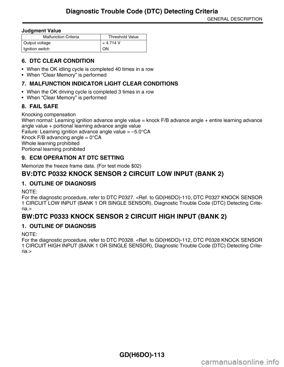
BV:DTC P0332 KNOCK SENSOR 2 CIRCUIT LOW INPUT (BANK 2)
1. OUTLINE OF DIAGNOSIS
NOTE:
For the diagnostic procedure, refer to DTC P0327.
1 CIRCUIT LOW INPUT (BANK 1 OR SINGLE SENSOR), Diagnostic Trouble Code (DTC) Detecting Crite-
ria.>
BW:DTC P0333 KNOCK SENSOR 2 CIRCUIT HIGH INPUT (BANK 2)
1. OUTLINE OF DIAGNOSIS
NOTE:
For the diagnostic procedure, refer to DTC P0328.
1 CIRCUIT HIGH INPUT (BANK 1 OR SINGLE SENSOR), Diagnostic Trouble Code (DTC) Detecting Crite-
ria.>
Judgment Value
Malfunction Criteria Threshold Value
Output voltage < 4.714 V
Ignition switch ON
Page 1727 of 2453
GD(H6DO)-115
Diagnostic Trouble Code (DTC) Detecting Criteria
GENERAL DESCRIPTION
4. GENERAL DRIVING CYCLE
Always perform the diagnosis continuously.
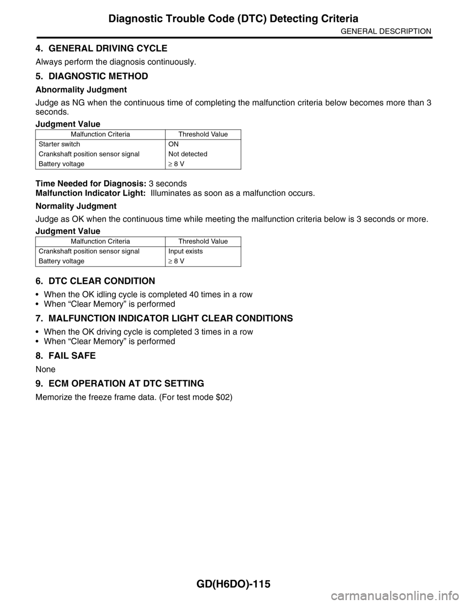
5. DIAGNOSTIC METHOD
Abnormality Judgment
Judge as NG when the continuous time of completing the malfunction criteria below becomes more than 3
seconds.
Time Needed for Diagnosis: 3 seconds
Malfunction Indicator Light: Illuminates as soon as a malfunction occurs.
Normality Judgment
Judge as OK when the continuous time while meeting the malfunction criteria below is 3 seconds or more.
6. DTC CLEAR CONDITION
•When the OK idling cycle is completed 40 times in a row
•When “Clear Memory” is performed
7. MALFUNCTION INDICATOR LIGHT CLEAR CONDITIONS
•When the OK driving cycle is completed 3 times in a row
•When “Clear Memory” is performed
8. FAIL SAFE
None
9. ECM OPERATION AT DTC SETTING
Memorize the freeze frame data. (For test mode $02)
Judgment Value
Malfunction Criteria Threshold Value
Starter switch ON
Crankshaft position sensor signal Not detected
Battery voltage≥ 8 V
Judgment Value
Malfunction Criteria Threshold Value
Crankshaft position sensor signal Input exists
Battery voltage≥ 8 V
Page 1729 of 2453
GD(H6DO)-117
Diagnostic Trouble Code (DTC) Detecting Criteria
GENERAL DESCRIPTION
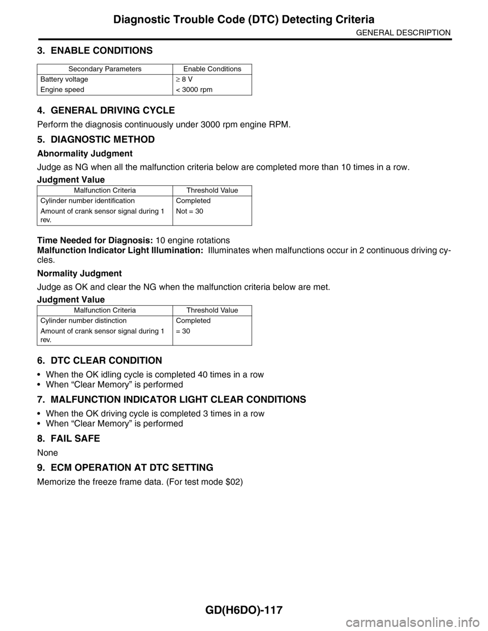
3. ENABLE CONDITIONS
4. GENERAL DRIVING CYCLE
Perform the diagnosis continuously under 3000 rpm engine RPM.
5. DIAGNOSTIC METHOD
Abnormality Judgment
Judge as NG when all the malfunction criteria below are completed more than 10 times in a row.
Time Needed for Diagnosis: 10 engine rotations
Malfunction Indicator Light Illumination: Illuminates when malfunctions occur in 2 continuous driving cy-
cles.
Normality Judgment
Judge as OK and clear the NG when the malfunction criteria below are met.
6. DTC CLEAR CONDITION
•When the OK idling cycle is completed 40 times in a row
•When “Clear Memory” is performed
7. MALFUNCTION INDICATOR LIGHT CLEAR CONDITIONS
•When the OK driving cycle is completed 3 times in a row
•When “Clear Memory” is performed
8. FAIL SAFE
None
9. ECM OPERATION AT DTC SETTING
Memorize the freeze frame data. (For test mode $02)
Secondary Parameters Enable Conditions
Battery voltage≥ 8 V
Engine speed < 3000 rpm
Judgment Value
Malfunction Criteria Threshold Value
Cylinder number identification Completed
Amount of crank sensor signal during 1
rev.
Not = 30
Judgment Value
Malfunction Criteria Threshold Value
Cylinder number distinction Completed
Amount of crank sensor signal during 1
rev.
= 30
Page 1731 of 2453
GD(H6DO)-119
Diagnostic Trouble Code (DTC) Detecting Criteria
GENERAL DESCRIPTION
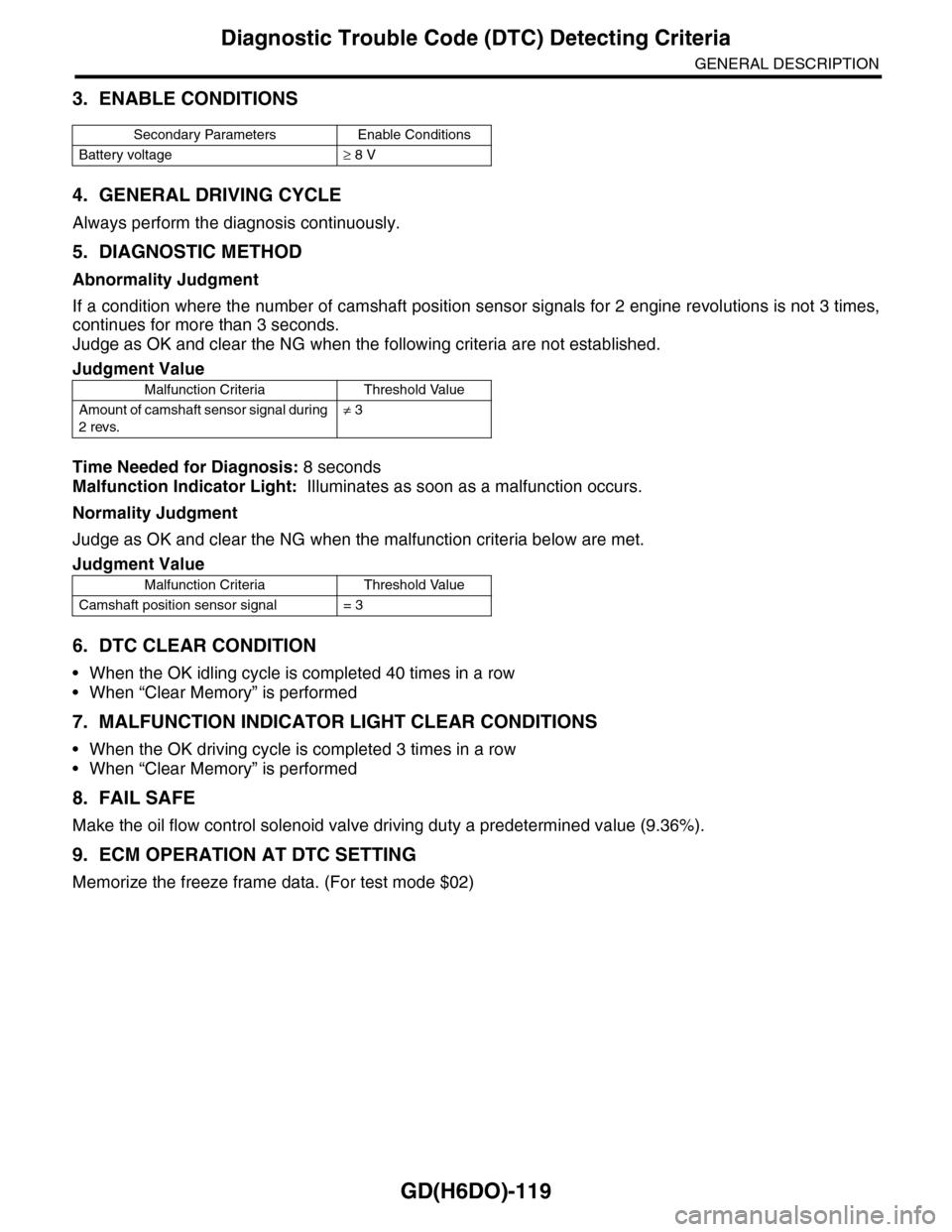
3. ENABLE CONDITIONS
4. GENERAL DRIVING CYCLE
Always perform the diagnosis continuously.
5. DIAGNOSTIC METHOD
Abnormality Judgment
If a condition where the number of camshaft position sensor signals for 2 engine revolutions is not 3 times,
continues for more than 3 seconds.
Judge as OK and clear the NG when the following criteria are not established.
Time Needed for Diagnosis: 8 seconds
Malfunction Indicator Light: Illuminates as soon as a malfunction occurs.
Normality Judgment
Judge as OK and clear the NG when the malfunction criteria below are met.
6. DTC CLEAR CONDITION
•When the OK idling cycle is completed 40 times in a row
•When “Clear Memory” is performed
7. MALFUNCTION INDICATOR LIGHT CLEAR CONDITIONS
•When the OK driving cycle is completed 3 times in a row
•When “Clear Memory” is performed
8. FAIL SAFE
Make the oil flow control solenoid valve driving duty a predetermined value (9.36%).
9. ECM OPERATION AT DTC SETTING
Memorize the freeze frame data. (For test mode $02)
Secondary Parameters Enable Conditions
Battery voltage≥ 8 V
Judgment Value
Malfunction Criteria Threshold Value
Amount of camshaft sensor signal during
2 revs.
≠ 3
Judgment Value
Malfunction Criteria Threshold Value
Camshaft position sensor signal = 3
Page 1735 of 2453
GD(H6DO)-123
Diagnostic Trouble Code (DTC) Detecting Criteria
GENERAL DESCRIPTION
6. DTC CLEAR CONDITION
•When the OK idling cycle is completed 40 times in a row
•When “Clear Memory” is performed
7. MALFUNCTION INDICATOR LIGHT CLEAR CONDITIONS
•When the OK driving cycle is completed 3 times in a row
•When “Clear Memory” is performed
8. FAIL SAFE
None
9. ECM OPERATION AT DTC SETTING
•Memorize the freeze frame data. (For test mode $02)
•Memorize the diagnostic value and trouble standard value. (For test mode $06)
Page 1736 of 2453
GD(H6DO)-124
Diagnostic Trouble Code (DTC) Detecting Criteria
GENERAL DESCRIPTION
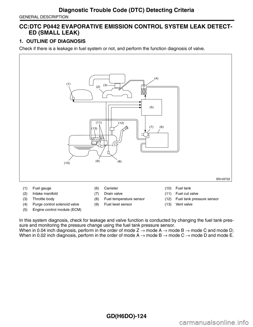
CC:DTC P0442 EVAPORATIVE EMISSION CONTROL SYSTEM LEAK DETECT-
ED (SMALL LEAK)
1. OUTLINE OF DIAGNOSIS
Check if there is a leakage in fuel system or not, and perform the function diagnosis of valve.
In this system diagnosis, check for leakage and valve function is conducted by changing the fuel tank pres-
sure and monitoring the pressure change using the fuel tank pressure sensor.
When in 0.04 inch diagnosis, perform in the order of mode Z → mode A → mode B → mode C and mode D;
When in 0.02 inch diagnosis, perform in the order of mode A → mode B → mode C → mode D and mode E.
(1) Fuel gauge (6) Canister (10) Fuel tank
(2) Intake manifold (7) Drain valve (11) Fuel cut valve
(3) Throttle body (8) Fuel temperature sensor (12) Fuel tank pressure sensor
(4) Purge control solenoid valve (9) Fuel level sensor (13) Vent valve
(5) Engine control module (ECM)
EN-03722
(1)(2)(3)
(4)
(5)
(6)
(8)
(12)
(9)(10)
(13)
(11)
(7)
Page 1737 of 2453
GD(H6DO)-125
Diagnostic Trouble Code (DTC) Detecting Criteria
GENERAL DESCRIPTION
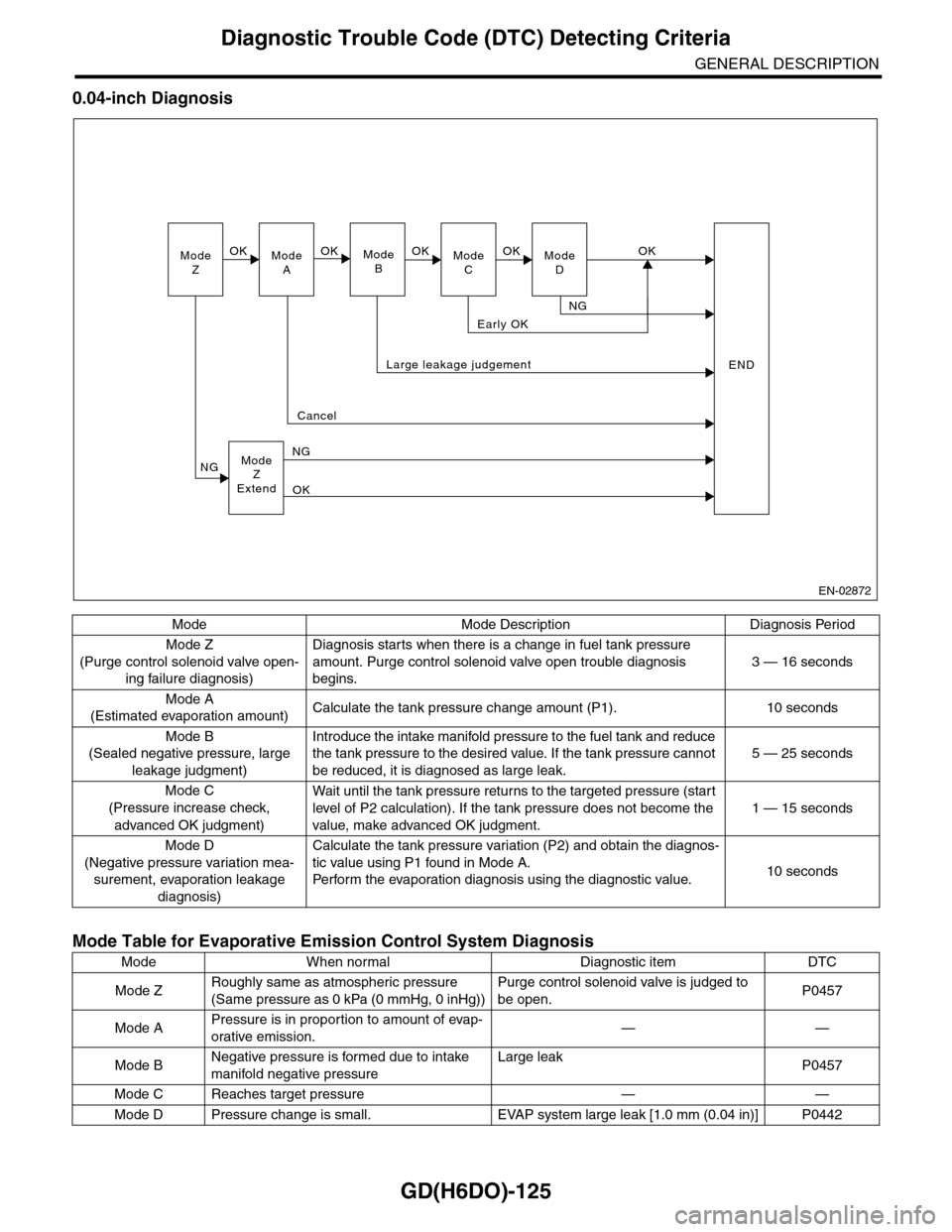
0.04-inch Diagnosis
Mode Mode Description Diagnosis Period
Mode Z
(Purge control solenoid valve open-
ing failure diagnosis)
Diagnosis starts when there is a change in fuel tank pressure
amount. Purge control solenoid valve open trouble diagnosis
begins.
3 — 16 seconds
Mode A
(Estimated evaporation amount)Calculate the tank pressure change amount (P1). 10 seconds
Mode B
(Sealed negative pressure, large
leakage judgment)
Introduce the intake manifold pressure to the fuel tank and reduce
the tank pressure to the desired value. If the tank pressure cannot
be reduced, it is diagnosed as large leak.
5 — 25 seconds
Mode C
(Pressure increase check,
advanced OK judgment)
Wait until the tank pressure retur ns to the targeted pressure (star t
level of P2 calculation). If the tank pressure does not become the
value, make advanced OK judgment.
1 — 15 seconds
Mode D
(Negative pressure variation mea-
surement, evaporation leakage
diagnosis)
Calculate the tank pressure variation (P2) and obtain the diagnos-
tic value using P1 found in Mode A.
Pe r fo r m t he eva po ra ti o n d ia g no si s u si n g t h e d ia g no st i c val u e.10 seconds
Mode Table for Evaporative Emission Control System Diagnosis
Mode When normal Diagnostic item DTC
Mode ZRoughly same as atmospheric pressure
(Same pressure as 0 kPa (0 mmHg, 0 inHg))
Purge control solenoid valve is judged to
be open.P0457
Mode APressure is in proportion to amount of evap-
orative emission.——
Mode BNegative pressure is formed due to intake
manifold negative pressure
Large leakP0457
Mode C Reaches target pressure — —
Mode D Pressure change is small. EVAP system large leak [1.0 mm (0.04 in)] P0442
ModeZModeAModeBModeCModeD
OKOKOKOKOK
NG
Early OK
Large leakage judgement
Cancel
ModeZExtend
NG
NG
OK
END
EN-02872