Page 2065 of 2453
5AT-49
Rear Vehicle Speed Sensor
AUTOMATIC TRANSMISSION
15.Rear Vehicle Speed Sensor
A: REMOVAL
1) Set the vehicle on a lift.
2) Disconnect the ground cable from battery.
3) Remove the air intake chamber.
IN(H6DO)-6, REMOVAL, Air Intake Chamber.>
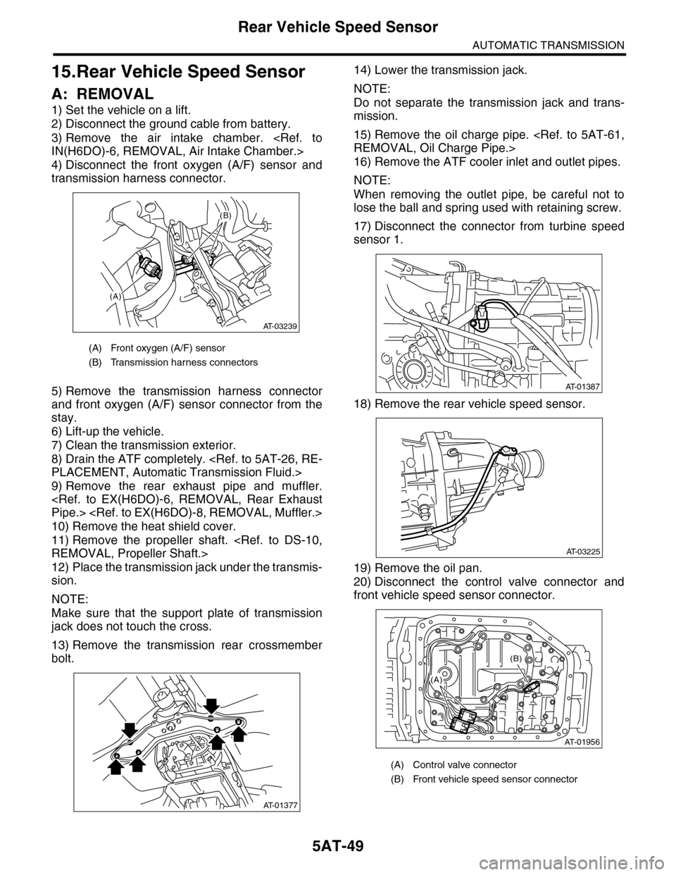
4) Disconnect the front oxygen (A/F) sensor and
transmission harness connector.
5) Remove the transmission harness connector
and front oxygen (A/F) sensor connector from the
stay.
6) Lift-up the vehicle.
7) Clean the transmission exterior.
8) Drain the ATF completely.
PLACEMENT, Automatic Transmission Fluid.>
9) Remove the rear exhaust pipe and muffler.
Pipe.>
10) Remove the heat shield cover.
11) Remove the propeller shaft.
REMOVAL, Propeller Shaft.>
12) Place the transmission jack under the transmis-
sion.
NOTE:
Make sure that the support plate of transmission
jack does not touch the cross.
13) Remove the transmission rear crossmember
bolt.
14) Lower the transmission jack.
NOTE:
Do not separate the transmission jack and trans-
mission.
15) Remove the oil charge pipe.
REMOVAL, Oil Charge Pipe.>
16) Remove the ATF cooler inlet and outlet pipes.
NOTE:
When removing the outlet pipe, be careful not to
lose the ball and spring used with retaining screw.
17) Disconnect the connector from turbine speed
sensor 1.
18) Remove the rear vehicle speed sensor.
19) Remove the oil pan.
20) Disconnect the control valve connector and
front vehicle speed sensor connector.
(A) Front oxygen (A/F) sensor
(B) Transmission harness connectors
(A)
(B)
AT-03239
AT-01377
(A) Control valve connector
(B) Front vehicle speed sensor connector
AT-01387
AT-03225
AT-01956
(B)
(A)
Page 2107 of 2453
5AT-91
AT Main Case
AUTOMATIC TRANSMISSION
34.AT Main Case
A: REMOVAL
1) Remove the transmission assembly from vehicle
body.
Transmission Assembly.>
2) Pull out the torque converter assembly.
5AT-62, REMOVAL, Torque Converter Assembly.>
3) Remove the transmission harness connector
from stay.
4) Disconnect the air breather hose.
5) Remove the oil charge pipe.
REMOVAL, Oil Charge Pipe.>
6) Remove the ATF filter inlet and outlet pipes.
Hose.>
7) Remove the extension case.
REMOVAL, Extension Case.>
8) Remove the center differential carrier.
5AT-71, REMOVAL, Center Differential Carrier.>
9) Remove the reduction driven gear.
68, REMOVAL, Reduction Driven Gear.>
10) Separate the converter case from the transmis-
sion case.
Case.>
11) Remove the control valve body.
53, REMOVAL, Control Valve Body.>
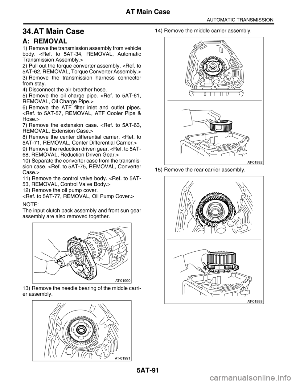
12) Remove the oil pump cover.
NOTE:
The input clutch pack assembly and front sun gear
assembly are also removed together.
13) Remove the needle bearing of the middle carri-
er assembly.
14) Remove the middle carrier assembly.
15) Remove the rear carrier assembly.
AT-01990
AT-01991
AT-01992
AT-01993
Page 2255 of 2453
CS-3
General Description
CONTROL SYSTEMS
B: PREPARATION TOOL
1. SPECIAL TOOL
(1) Ring indicator (21) Clamp (41) Air flow control switch
(2) Front cover (22) Base ASSY (42) Arm ASSY
(3) Grip ASSY (23) Spacer (43) Bushing
(4) Grip pin (24) Harness connector (44) Dust cover bracket
(5) Grip cover (25) Shift-up switch (45) Dust cover
(6) Indicator ASSY (26) “P” range switch (46) Cable bracket
(7) Shift blind (27) Shift-down switch (47) Washer
(8) Blind A (28) Shaft (48) Cotter pin
(9) Blind B (29) Detent check block (49) Select cable
(10) Position plate (30) Shift lock solenoid (50) Clamp
(11) Plate lamp guide (31) Check sheet pole (51) Adjusting nut A
(12) Valve case (32) Spring (52) Button rod
(13) Indicator bulb (33) Select shaft (53) Pusher
(14) Valve harness (34) Shift position pin (54) Selector arm ASSY
(15) Release rod (35) Shift button switch (55) Spacer
(16) Spring (36) Spring
(17) Lock lever bracket (37) WasherTightening torque: N·m (kgf-m, ft-lb)
(18) Lock lever bushing (38) Spring washerT1: 5.1 (0.52, 3.8)
(19) Bushing (39) Tube cross plateT2: 7.5 (0.76, 5.5)
(20) Lock lever (40) BushingT3: 18 (1.8, 13.3)
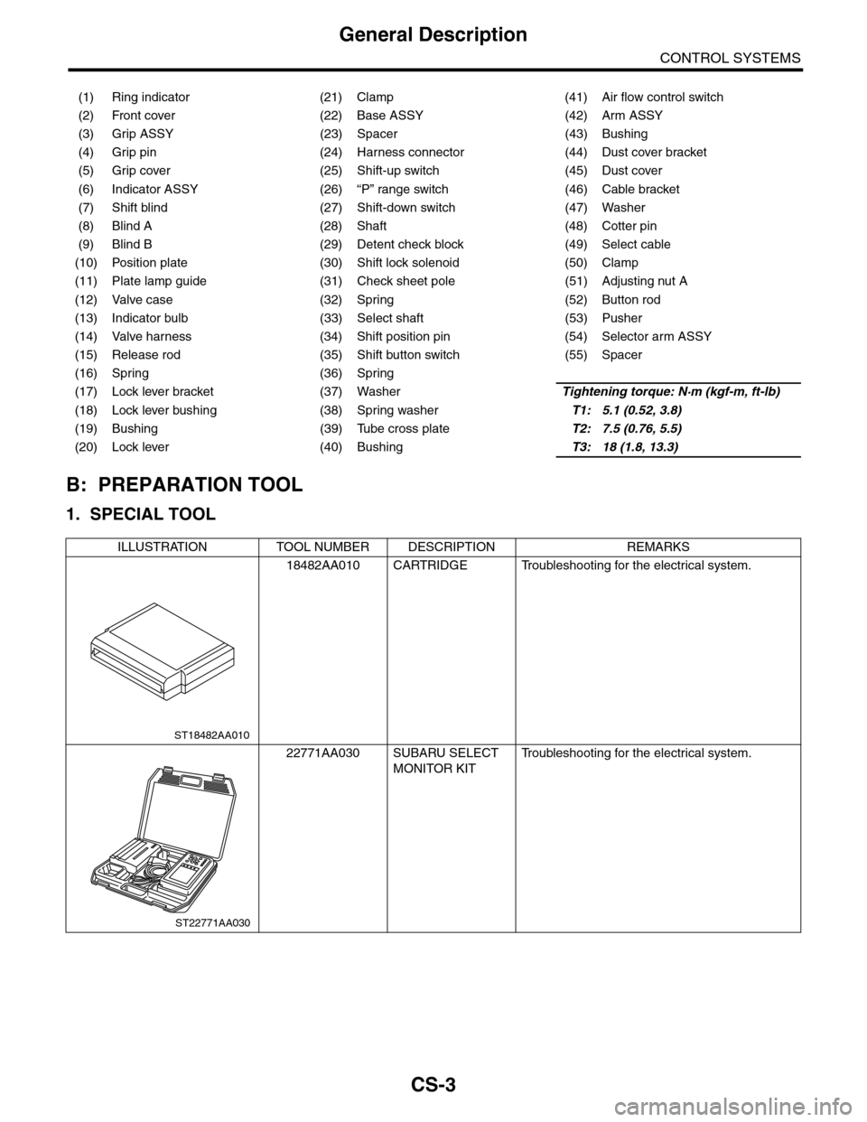
ILLUSTRATION TOOL NUMBER DESCRIPTION REMARKS
18482AA010 CARTRIDGE Troubleshooting for the electrical system.
22771AA030 SUBARU SELECT
MONITOR KIT
Tr o u b l e s h o o t i n g f o r t h e e l e c t r i c a l s y s t e m .
ST18482AA010
ST22771AA030