2009 SUBARU TRIBECA monitor
[x] Cancel search: monitorPage 2244 of 2453
5AT(diag)-127
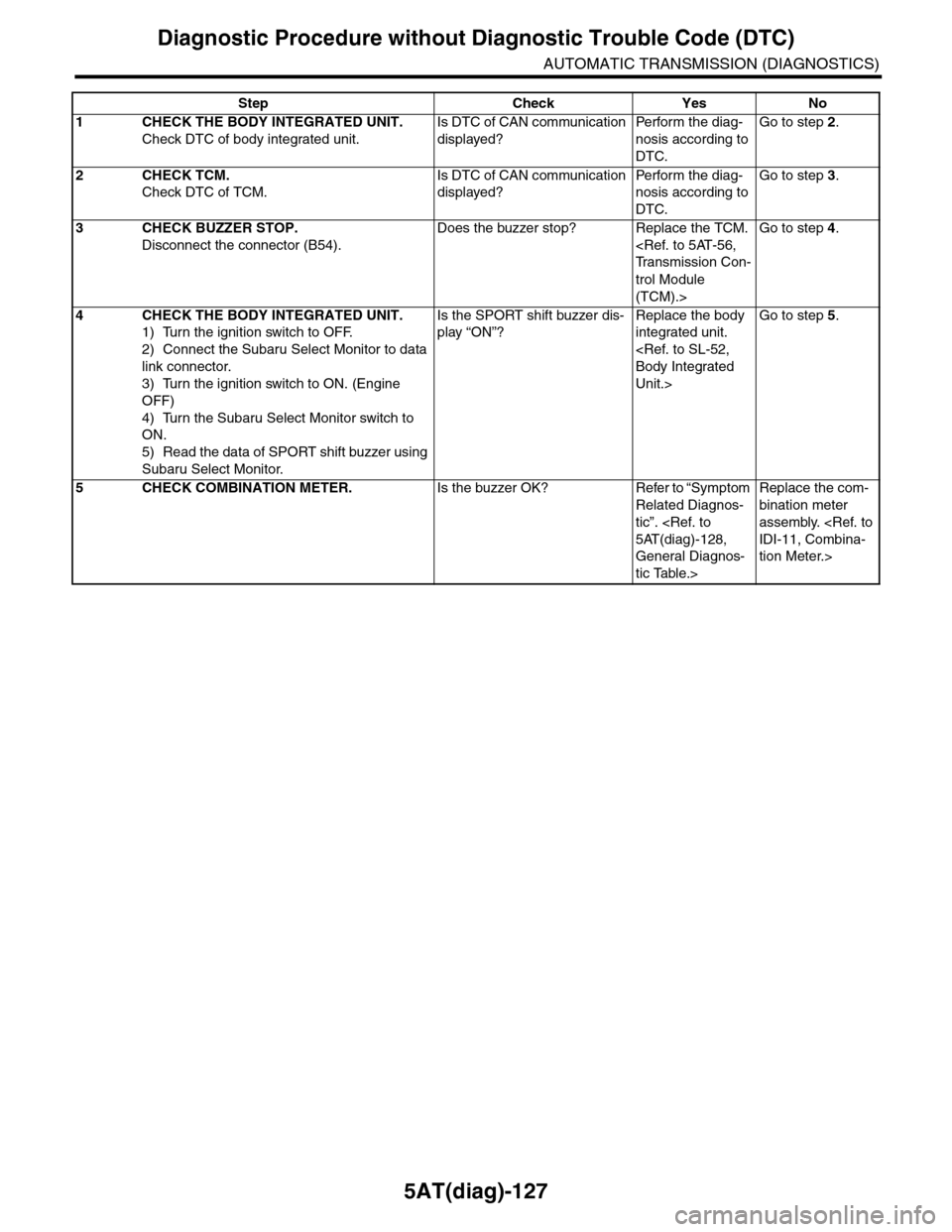
Diagnostic Procedure without Diagnostic Trouble Code (DTC)
AUTOMATIC TRANSMISSION (DIAGNOSTICS)
Step Check Yes No
1CHECK THE BODY INTEGRATED UNIT.
Check DTC of body integrated unit.
Is DTC of CAN communication
displayed?
Pe r for m t h e d ia g -
nosis according to
DTC.
Go to step 2.
2CHECK TCM.
Check DTC of TCM.
Is DTC of CAN communication
displayed?
Pe r for m t h e d ia g -
nosis according to
DTC.
Go to step 3.
3CHECK BUZZER STOP.
Disconnect the connector (B54).
Does the buzzer stop? Replace the TCM.
trol Module
(TCM).>
Go to step 4.
4CHECK THE BODY INTEGRATED UNIT.
1) Turn the ignition switch to OFF.
2) Connect the Subaru Select Monitor to data
link connector.
3) Turn the ignition switch to ON. (Engine
OFF)
4) Turn the Subaru Select Monitor switch to
ON.
5) Read the data of SPORT shift buzzer using
Subaru Select Monitor.
Is the SPORT shift buzzer dis-
play “ON”?
Replace the body
integrated unit.
Unit.>
Go to step 5.
5CHECK COMBINATION METER.Is the buzzer OK? Refer to “Symptom
Related Diagnos-
tic”.
General Diagnos-
tic Table.>
Replace the com-
bination meter
assembly.
tion Meter.>
Page 2255 of 2453
CS-3
General Description
CONTROL SYSTEMS
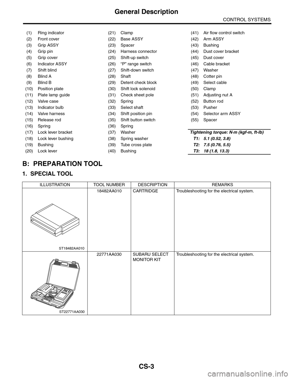
B: PREPARATION TOOL
1. SPECIAL TOOL
(1) Ring indicator (21) Clamp (41) Air flow control switch
(2) Front cover (22) Base ASSY (42) Arm ASSY
(3) Grip ASSY (23) Spacer (43) Bushing
(4) Grip pin (24) Harness connector (44) Dust cover bracket
(5) Grip cover (25) Shift-up switch (45) Dust cover
(6) Indicator ASSY (26) “P” range switch (46) Cable bracket
(7) Shift blind (27) Shift-down switch (47) Washer
(8) Blind A (28) Shaft (48) Cotter pin
(9) Blind B (29) Detent check block (49) Select cable
(10) Position plate (30) Shift lock solenoid (50) Clamp
(11) Plate lamp guide (31) Check sheet pole (51) Adjusting nut A
(12) Valve case (32) Spring (52) Button rod
(13) Indicator bulb (33) Select shaft (53) Pusher
(14) Valve harness (34) Shift position pin (54) Selector arm ASSY
(15) Release rod (35) Shift button switch (55) Spacer
(16) Spring (36) Spring
(17) Lock lever bracket (37) WasherTightening torque: N·m (kgf-m, ft-lb)
(18) Lock lever bushing (38) Spring washerT1: 5.1 (0.52, 3.8)
(19) Bushing (39) Tube cross plateT2: 7.5 (0.76, 5.5)
(20) Lock lever (40) BushingT3: 18 (1.8, 13.3)
ILLUSTRATION TOOL NUMBER DESCRIPTION REMARKS
18482AA010 CARTRIDGE Troubleshooting for the electrical system.
22771AA030 SUBARU SELECT
MONITOR KIT
Tr o u b l e s h o o t i n g f o r t h e e l e c t r i c a l s y s t e m .
ST18482AA010
ST22771AA030
Page 2265 of 2453
CS-13
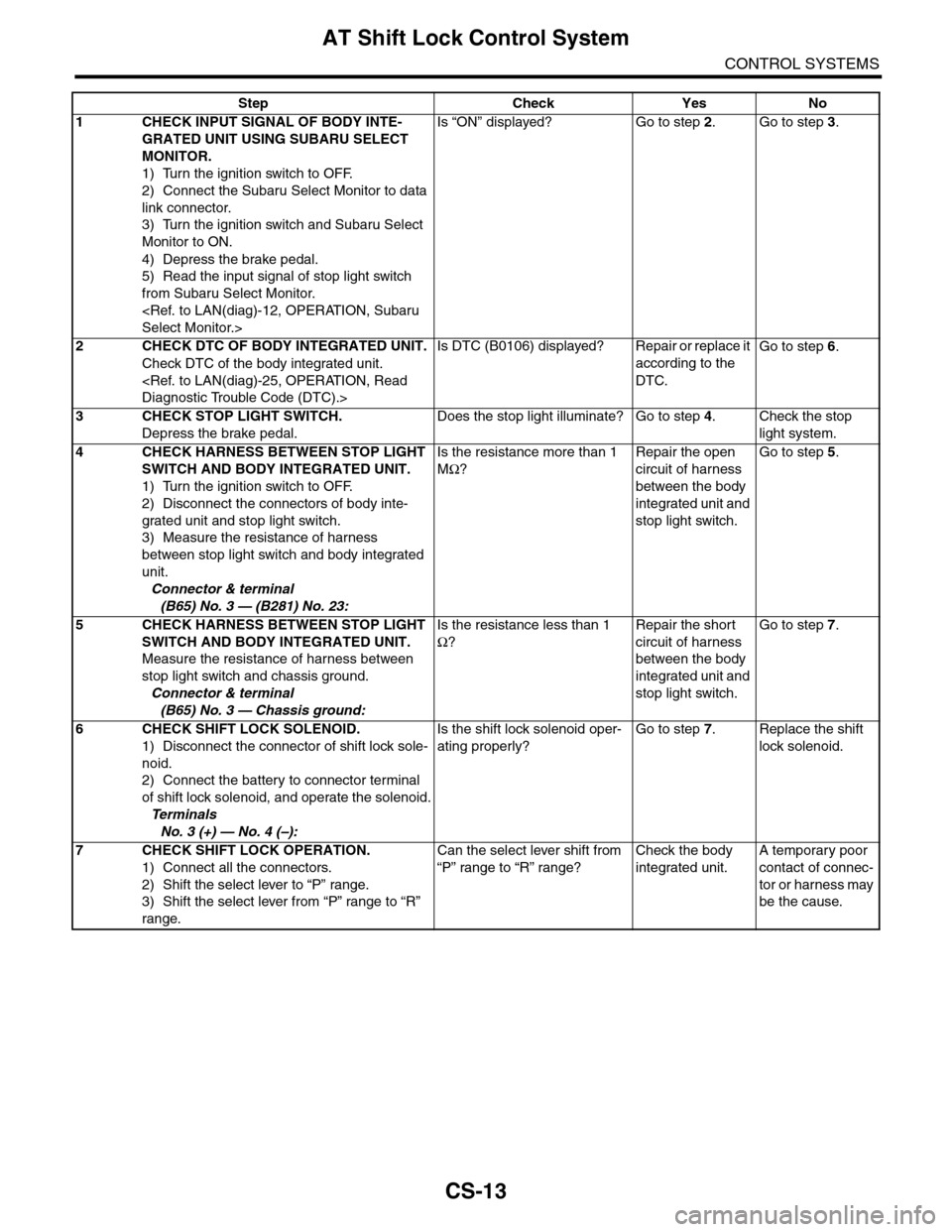
AT Shift Lock Control System
CONTROL SYSTEMS
Step Check Yes No
1CHECK INPUT SIGNAL OF BODY INTE-
GRATED UNIT USING SUBARU SELECT
MONITOR.
1) Turn the ignition switch to OFF.
2) Connect the Subaru Select Monitor to data
link connector.
3) Turn the ignition switch and Subaru Select
Monitor to ON.
4) Depress the brake pedal.
5) Read the input signal of stop light switch
from Subaru Select Monitor.
Is “ON” displayed? Go to step 2.Go to step 3.
2CHECK DTC OF BODY INTEGRATED UNIT.
Check DTC of the body integrated unit.
Is DTC (B0106) displayed? Repair or replace it
according to the
DTC.
Go to step 6.
3CHECK STOP LIGHT SWITCH.
Depress the brake pedal.
Does the stop light illuminate? Go to step 4.Check the stop
light system.
4CHECK HARNESS BETWEEN STOP LIGHT
SWITCH AND BODY INTEGRATED UNIT.
1) Turn the ignition switch to OFF.
2) Disconnect the connectors of body inte-
grated unit and stop light switch.
3) Measure the resistance of harness
between stop light switch and body integrated
unit.
Connector & terminal
(B65) No. 3 — (B281) No. 23:
Is the resistance more than 1
MΩ?
Repair the open
circuit of harness
between the body
integrated unit and
stop light switch.
Go to step 5.
5CHECK HARNESS BETWEEN STOP LIGHT
SWITCH AND BODY INTEGRATED UNIT.
Measure the resistance of harness between
stop light switch and chassis ground.
Connector & terminal
(B65) No. 3 — Chassis ground:
Is the resistance less than 1
Ω?
Repair the short
circuit of harness
between the body
integrated unit and
stop light switch.
Go to step 7.
6CHECK SHIFT LOCK SOLENOID.
1) Disconnect the connector of shift lock sole-
noid.
2) Connect the battery to connector terminal
of shift lock solenoid, and operate the solenoid.
Te r m i n a l s
No. 3 (+) — No. 4 (–):
Is the shift lock solenoid oper-
ating properly?
Go to step 7.Replace the shift
lock solenoid.
7CHECK SHIFT LOCK OPERATION.
1) Connect all the connectors.
2) Shift the select lever to “P” range.
3) Shift the select lever from “P” range to “R”
range.
Can the select lever shift from
“P” range to “R” range?
Check the body
integrated unit.
A temporary poor
contact of connec-
tor or harness may
be the cause.
Page 2267 of 2453
CS-15
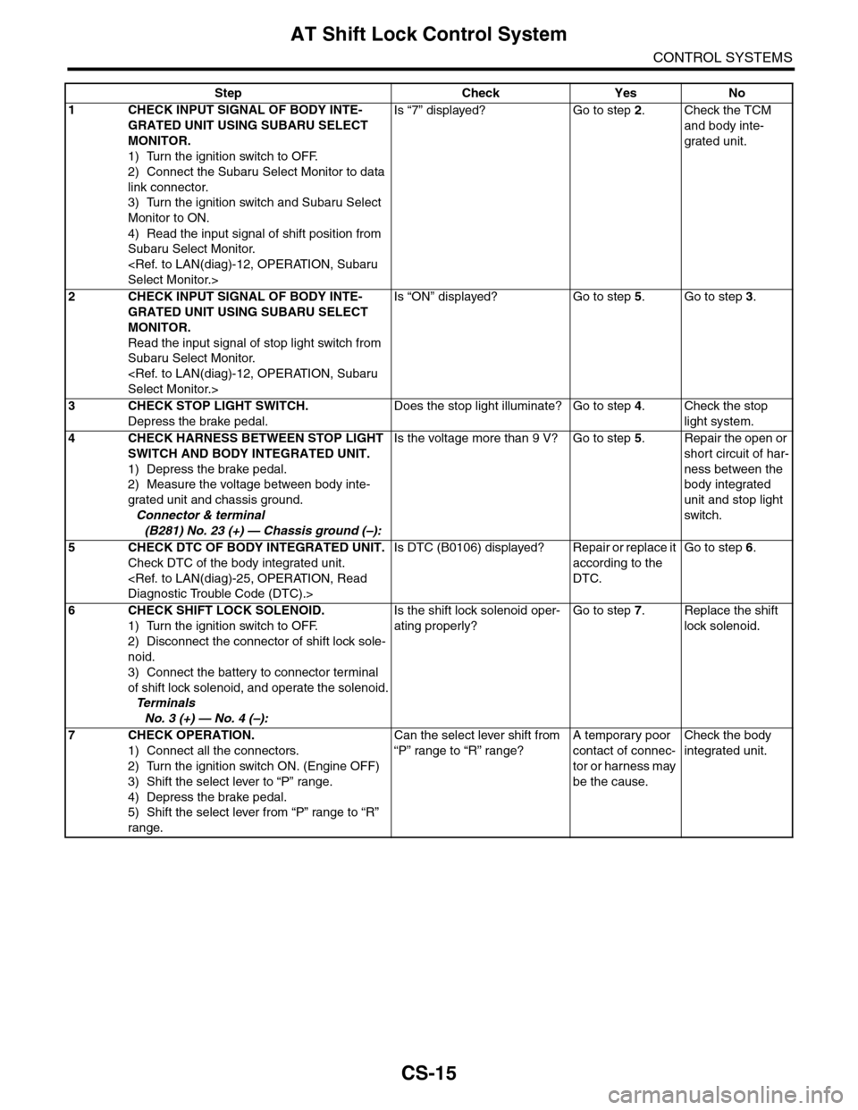
AT Shift Lock Control System
CONTROL SYSTEMS
Step Check Yes No
1CHECK INPUT SIGNAL OF BODY INTE-
GRATED UNIT USING SUBARU SELECT
MONITOR.
1) Turn the ignition switch to OFF.
2) Connect the Subaru Select Monitor to data
link connector.
3) Turn the ignition switch and Subaru Select
Monitor to ON.
4) Read the input signal of shift position from
Subaru Select Monitor.
Is “7” displayed? Go to step 2.Check the TCM
and body inte-
grated unit.
2CHECK INPUT SIGNAL OF BODY INTE-
GRATED UNIT USING SUBARU SELECT
MONITOR.
Read the input signal of stop light switch from
Subaru Select Monitor.
Is “ON” displayed? Go to step 5.Go to step 3.
3CHECK STOP LIGHT SWITCH.
Depress the brake pedal.
Does the stop light illuminate? Go to step 4.Check the stop
light system.
4CHECK HARNESS BETWEEN STOP LIGHT
SWITCH AND BODY INTEGRATED UNIT.
1) Depress the brake pedal.
2) Measure the voltage between body inte-
grated unit and chassis ground.
Connector & terminal
(B281) No. 23 (+) — Chassis ground (–):
Is the voltage more than 9 V? Go to step 5.Repair the open or
short circuit of har-
ness between the
body integrated
unit and stop light
switch.
5CHECK DTC OF BODY INTEGRATED UNIT.
Check DTC of the body integrated unit.
Is DTC (B0106) displayed? Repair or replace it
according to the
DTC.
Go to step 6.
6CHECK SHIFT LOCK SOLENOID.
1) Turn the ignition switch to OFF.
2) Disconnect the connector of shift lock sole-
noid.
3) Connect the battery to connector terminal
of shift lock solenoid, and operate the solenoid.
Te r m i n a l s
No. 3 (+) — No. 4 (–):
Is the shift lock solenoid oper-
ating properly?
Go to step 7.Replace the shift
lock solenoid.
7CHECK OPERATION.
1) Connect all the connectors.
2) Turn the ignition switch ON. (Engine OFF)
3) Shift the select lever to “P” range.
4) Depress the brake pedal.
5) Shift the select lever from “P” range to “R”
range.
Can the select lever shift from
“P” range to “R” range?
A temporary poor
contact of connec-
tor or harness may
be the cause.
Check the body
integrated unit.
Page 2269 of 2453
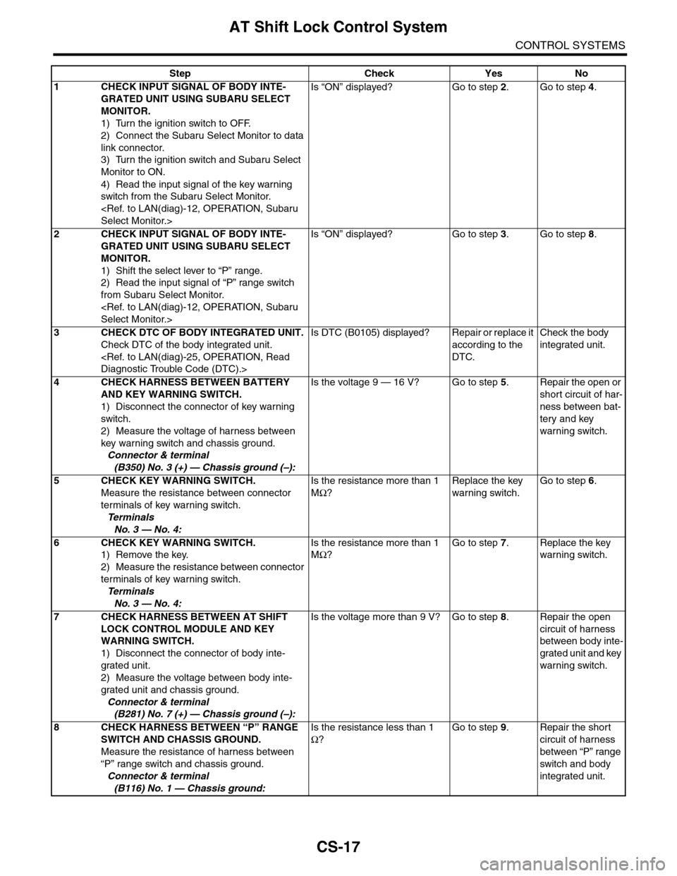
CS-17
AT Shift Lock Control System
CONTROL SYSTEMS
Step Check Yes No
1CHECK INPUT SIGNAL OF BODY INTE-
GRATED UNIT USING SUBARU SELECT
MONITOR.
1) Turn the ignition switch to OFF.
2) Connect the Subaru Select Monitor to data
link connector.
3) Turn the ignition switch and Subaru Select
Monitor to ON.
4) Read the input signal of the key warning
switch from the Subaru Select Monitor.
Is “ON” displayed? Go to step 2.Go to step 4.
2CHECK INPUT SIGNAL OF BODY INTE-
GRATED UNIT USING SUBARU SELECT
MONITOR.
1) Shift the select lever to “P” range.
2) Read the input signal of “P” range switch
from Subaru Select Monitor.
Is “ON” displayed? Go to step 3.Go to step 8.
3CHECK DTC OF BODY INTEGRATED UNIT.
Check DTC of the body integrated unit.
Is DTC (B0105) displayed? Repair or replace it
according to the
DTC.
Check the body
integrated unit.
4CHECK HARNESS BETWEEN BATTERY
AND KEY WARNING SWITCH.
1) Disconnect the connector of key warning
switch.
2) Measure the voltage of harness between
key warning switch and chassis ground.
Connector & terminal
(B350) No. 3 (+) — Chassis ground (–):
Is the voltage 9 — 16 V? Go to step 5.Repair the open or
short circuit of har-
ness between bat-
tery and key
warning switch.
5 CHECK KEY WARNING SWITCH.
Measure the resistance between connector
terminals of key warning switch.
Te r m i n a l s
No. 3 — No. 4:
Is the resistance more than 1
MΩ?
Replace the key
warning switch.
Go to step 6.
6 CHECK KEY WARNING SWITCH.
1) Remove the key.
2) Measure the resistance between connector
terminals of key warning switch.
Te r m i n a l s
No. 3 — No. 4:
Is the resistance more than 1
MΩ?
Go to step 7.Replace the key
warning switch.
7CHECK HARNESS BETWEEN AT SHIFT
LOCK CONTROL MODULE AND KEY
WARNING SWITCH.
1) Disconnect the connector of body inte-
grated unit.
2) Measure the voltage between body inte-
grated unit and chassis ground.
Connector & terminal
(B281) No. 7 (+) — Chassis ground (–):
Is the voltage more than 9 V? Go to step 8.Repair the open
circuit of harness
between body inte-
grated unit and key
warning switch.
8CHECK HARNESS BETWEEN “P” RANGE
SWITCH AND CHASSIS GROUND.
Measure the resistance of harness between
“P” range switch and chassis ground.
Connector & terminal
(B116) No. 1 — Chassis ground:
Is the resistance less than 1
Ω?
Go to step 9.Repair the short
circuit of harness
between “P” range
switch and body
integrated unit.
Page 2297 of 2453
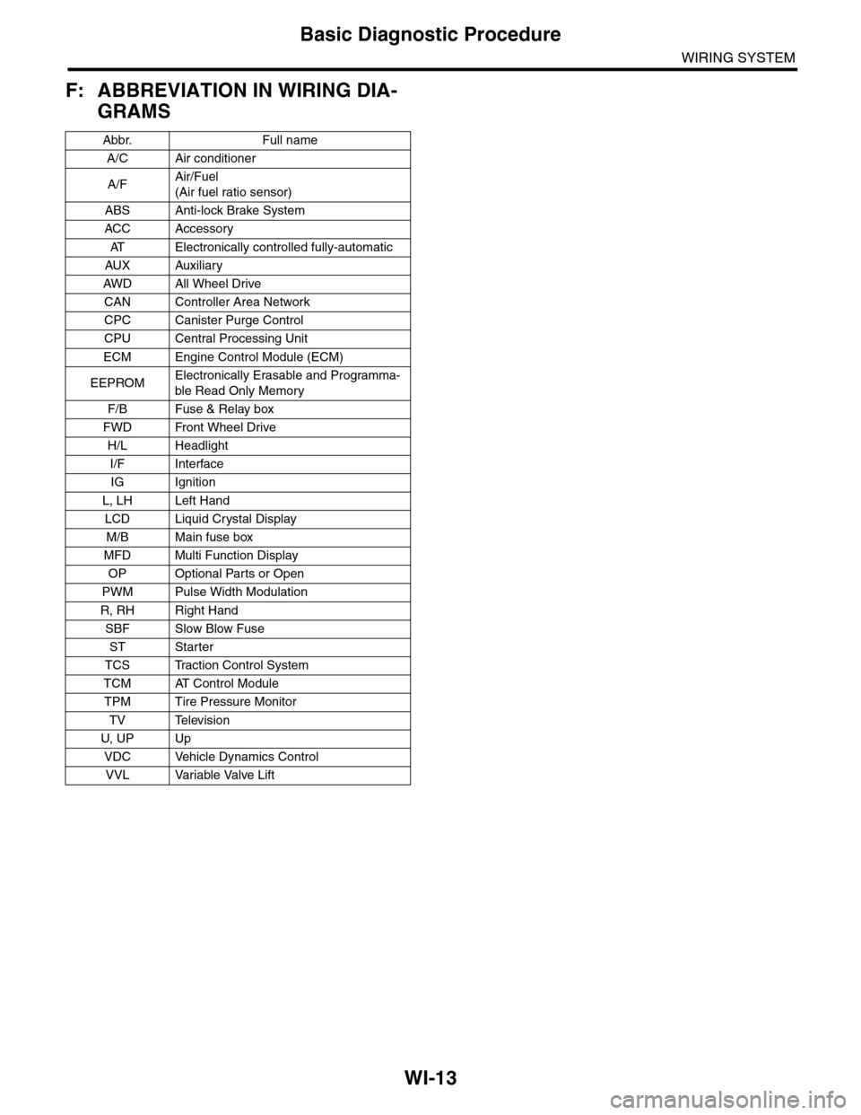
WI-13
Basic Diagnostic Procedure
WIRING SYSTEM
F: ABBREVIATION IN WIRING DIA-
GRAMS
Abbr. Full name
A/C Air conditioner
A/FAir/Fuel
(Air fuel ratio sensor)
ABS Anti-lock Brake System
ACC Accessor y
AT E l e c t r o n i c a l l y c o n t r o l l e d f u l l y - a u t o m a t i c
AUX Auxiliar y
AW D A ll W he e l D r i ve
CAN Controller Area Network
CPC Canister Purge Control
CPU Central Processing Unit
ECM Engine Control Module (ECM)
EEPROMElectronically Erasable and Programma-
ble Read Only Memory
F/B Fuse & Relay box
FWD Front Wheel Drive
H/L Headlight
I/F Interface
IG Ignition
L, LH Left Hand
LCD Liquid Crystal Display
M/B Main fuse box
MFD Multi Function Display
OP Optional Parts or Open
PWM Pulse Width Modulation
R, RH Right Hand
SBF Slow Blow Fuse
ST Starter
TCS Traction Control System
TCM AT Control Module
TPM Tire Pressure Monitor
TV Television
U, UP Up
VDC Vehicle Dynamics Control
VVL Variable Valve Lift
Page 2304 of 2453
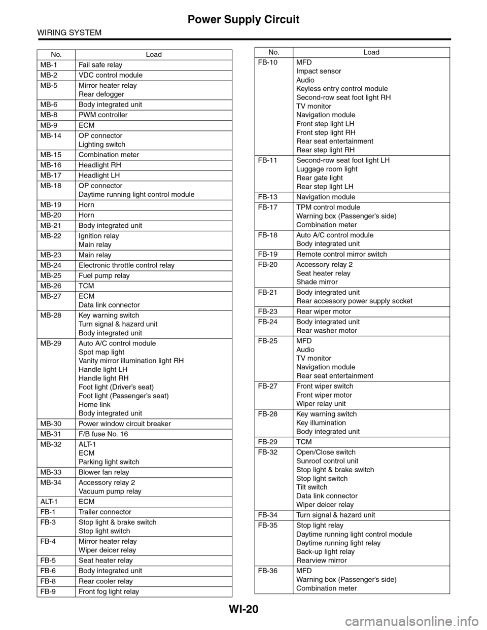
WI-20
Power Supply Circuit
WIRING SYSTEM
No. Load
MB-1 Fail safe relay
MB-2 VDC control module
MB-5 Mirror heater relay
Rear defogger
MB-6 Body integrated unit
MB-8 PWM controller
MB-9 ECM
MB-14 OP connector
Lighting switch
MB-15 Combination meter
MB-16 Headlight RH
MB-17 Headlight LH
MB-18 OP connector
Daytime running light control module
MB-19 Horn
MB-20 Horn
MB-21 Body integrated unit
MB-22 Ignition relay
Main relay
MB-23 Main relay
MB-24 Electronic throttle control relay
MB-25 Fuel pump relay
MB-26 TCM
MB-27 ECM
Data link connector
MB-28 Key warning switch
Tu r n s i g n a l & h a z a r d u n i t
Body integrated unit
MB-29 Auto A/C control module
Spot map light
Va n i t y m i r r o r i l l u m i n a t i o n l i g h t R H
Handle light LH
Handle light RH
Foot light (Driver’s seat)
Foot light (Passenger’s seat)
Home link
Body integrated unit
MB-30 Power window circuit breaker
MB-31 F/B fuse No. 16
MB-32 ALT-1
ECM
Par king light switch
MB-33 Blower fan relay
MB-34 Accessory relay 2
Va c u u m p u m p r e l ay
ALT-1 ECM
FB-1 Trailer connector
FB-3 Stop light & brake switch
Stop light switch
FB-4 Mirror heater relay
Wiper deicer relay
FB-5 Seat heater relay
FB-6 Body integrated unit
FB-8 Rear cooler relay
FB-9 Front fog light relay
FB-10 MFD
Impact sensor
Audio
Keyless entr y control module
Second-row seat foot light RH
TV monitor
Navigation module
Fr o n t s te p li gh t LH
Fr o n t s te p li gh t RH
Rear seat entertainment
Rear step light RH
FB-11 Second-row seat foot light LH
Luggage room light
Rear gate light
Rear step light LH
FB-13 Navigation module
FB-17 TPM control module
War ning box (Passenger’s side)
Combination meter
FB-18 Auto A/C control module
Body integrated unit
FB-19 Remote control mirror switch
FB-20 Accessory relay 2
Seat heater relay
Shade mirror
FB-21 Body integrated unit
Rear accessory power supply socket
FB-23 Rear wiper motor
FB-24 Body integrated unit
Rear washer motor
FB-25 MFD
Audio
TV monitor
Navigation module
Rear seat entertainment
FB-27 Front wiper switch
Fr o n t wi p er mo t or
Wiper relay unit
FB-28 Key warning switch
Key illumination
Body integrated unit
FB-29 TCM
FB-32 Open/Close switch
Sunroof control unit
Stop light & brake switch
Stop light switch
Tilt switch
Data link connector
Wiper deicer relay
FB-34 Turn signal & hazard unit
FB-35 Stop light relay
Daytime running light control module
Daytime running light relay
Back-up light relay
Rearview mirror
FB-36 MFD
War ning box (Passenger’s side)
Combination meter
No. Load
Page 2305 of 2453
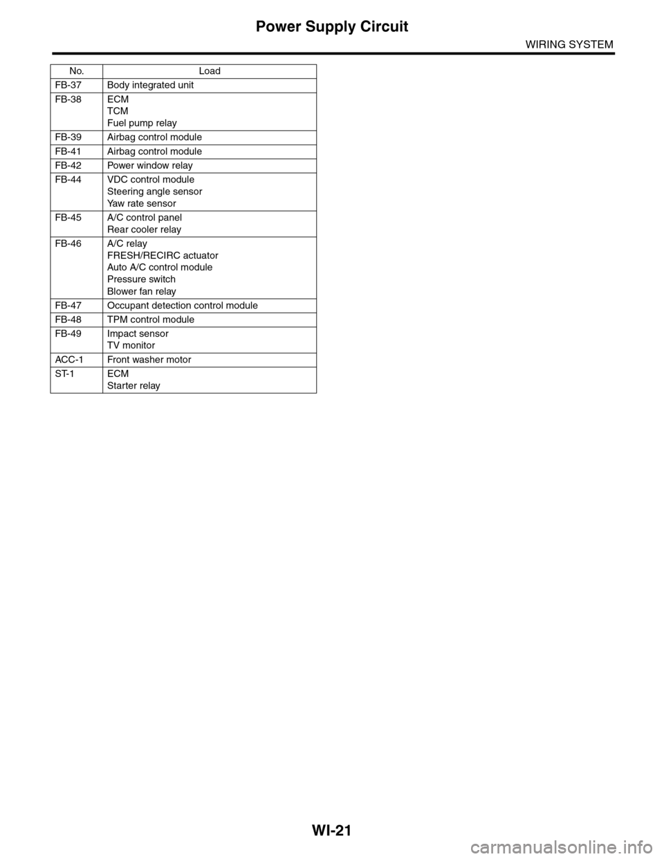
WI-21
Power Supply Circuit
WIRING SYSTEM
FB-37 Body integrated unit
FB-38 ECM
TCM
Fuel pump relay
FB-39 Airbag control module
FB-41 Airbag control module
FB-42 Power window relay
FB-44 VDC control module
Steering angle sensor
Ya w r a t e s e n s o r
FB-45 A/C control panel
Rear cooler relay
FB-46 A/C relay
FRESH/RECIRC actuator
Auto A/C control module
Pressure switch
Blower fan relay
FB-47 Occupant detection control module
FB-48 TPM control module
FB-49 Impact sensor
TV monitor
ACC -1 Front washer motor
ST-1 ECM
Starter relay
No. Load