2009 SUBARU TRIBECA monitor
[x] Cancel search: monitorPage 2049 of 2453
5AT-33
Transfer Clutch Pressure Test
AUTOMATIC TRANSMISSION
8. Transfer Clutch Pressure
Test
A: INSPECTION
1) Lift-up the vehicle.
2) Remove the bolts holding the heat shield cover,
and move the heat shield cover to the rear.
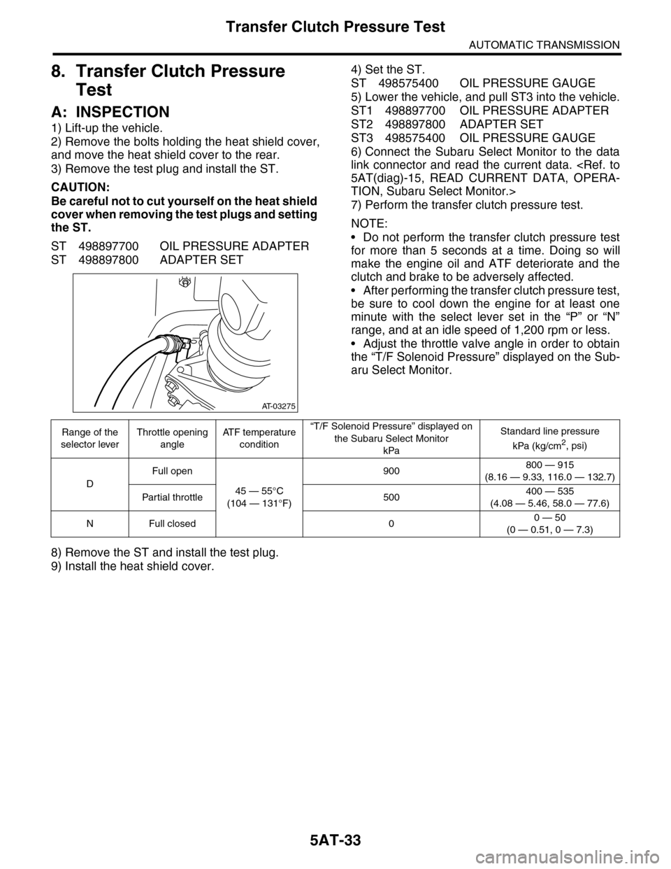
3) Remove the test plug and install the ST.
CAUTION:
Be careful not to cut yourself on the heat shield
cover when removing the test plugs and setting
the ST.
ST 498897700 OIL PRESSURE ADAPTER
ST 498897800 ADAPTER SET
4) Set the ST.
ST 498575400 OIL PRESSURE GAUGE
5) Lower the vehicle, and pull ST3 into the vehicle.
ST1 498897700 OIL PRESSURE ADAPTER
ST2 498897800 ADAPTER SET
ST3 498575400 OIL PRESSURE GAUGE
6) Connect the Subaru Select Monitor to the data
link connector and read the current data.
TION, Subaru Select Monitor.>
7) Perform the transfer clutch pressure test.
NOTE:
•Do not perform the transfer clutch pressure test
for more than 5 seconds at a time. Doing so will
make the engine oil and ATF deteriorate and the
clutch and brake to be adversely affected.
•After performing the transfer clutch pressure test,
be sure to cool down the engine for at least one
minute with the select lever set in the “P” or “N”
range, and at an idle speed of 1,200 rpm or less.
•Adjust the throttle valve angle in order to obtain
the “T/F Solenoid Pressure” displayed on the Sub-
aru Select Monitor.
8) Remove the ST and install the test plug.
9) Install the heat shield cover.
AT-03275
Range of the
selector lever
Throttle opening
angle
AT F t e m p e r a t u r e
condition
“T/F Solenoid Pressure” displayed on
the Subaru Select Monitor
kPa
Standard line pressure
kPa (kg/cm2, psi)
D
Full open
45 — 55°C
(104 — 131°F)
900800 — 915
(8.16 — 9.33, 116.0 — 132.7)
Par tial throttle 500400 — 535
(4.08 — 5.46, 58.0 — 77.6)
NFull closed 00 — 50
(0 — 0.51, 0 — 7.3)
Page 2056 of 2453
5AT-40
Automatic Transmission Assembly
AUTOMATIC TRANSMISSION
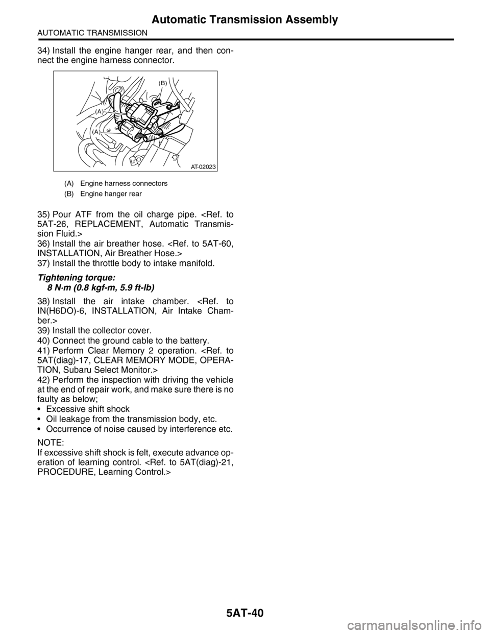
34) Install the engine hanger rear, and then con-
nect the engine harness connector.
35) Pour ATF from the oil charge pipe.
sion Fluid.>
36) Install the air breather hose.
37) Install the throttle body to intake manifold.
Tightening torque:
8 N·m (0.8 kgf-m, 5.9 ft-lb)
38) Install the air intake chamber.
ber.>
39) Install the collector cover.
40) Connect the ground cable to the battery.
41) Perform Clear Memory 2 operation.
TION, Subaru Select Monitor.>
42) Perform the inspection with driving the vehicle
at the end of repair work, and make sure there is no
faulty as below;
•Excessive shift shock
•Oil leakage from the transmission body, etc.
•Occurrence of noise caused by interference etc.
NOTE:
If excessive shift shock is felt, execute advance op-
eration of learning control.
(A) Engine harness connectors
(B) Engine hanger rear
(B)
(A)
(A)
AT-02023
Page 2070 of 2453
5AT-54
Control Valve Body
AUTOMATIC TRANSMISSION
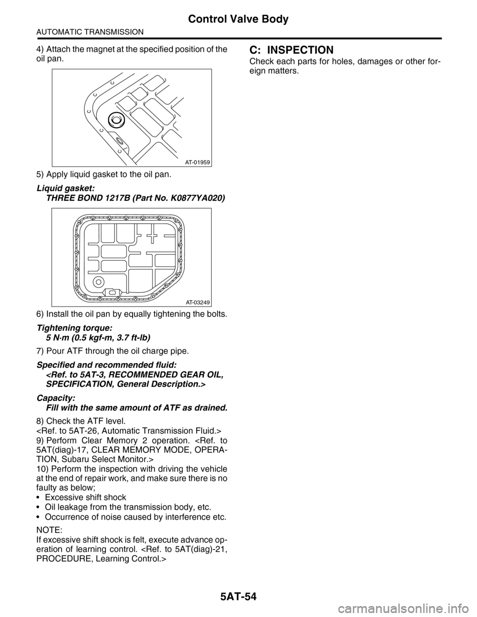
4) Attach the magnet at the specified position of the
oil pan.
5) Apply liquid gasket to the oil pan.
Liquid gasket:
THREE BOND 1217B (Part No. K0877YA020)
6) Install the oil pan by equally tightening the bolts.
Tightening torque:
5 N·m (0.5 kgf-m, 3.7 ft-lb)
7) Pour ATF through the oil charge pipe.
Specified and recommended fluid:
Capacity:
Fill with the same amount of ATF as drained.
8) Check the ATF level.
9) Perform Clear Memory 2 operation.
TION, Subaru Select Monitor.>
10) Perform the inspection with driving the vehicle
at the end of repair work, and make sure there is no
faulty as below;
•Excessive shift shock
•Oil leakage from the transmission body, etc.
•Occurrence of noise caused by interference etc.
NOTE:
If excessive shift shock is felt, execute advance op-
eration of learning control.
C: INSPECTION
Check each parts for holes, damages or other for-
eign matters.
AT-01959
AT-03249
Page 2072 of 2453
5AT-56
Transmission Control Module (TCM)
AUTOMATIC TRANSMISSION
19.Transmission Control Mod-
ule (TCM)
A: REMOVAL
1) Disconnect the ground cable from battery.
2) Remove the lower cover and then disconnect
the connector.
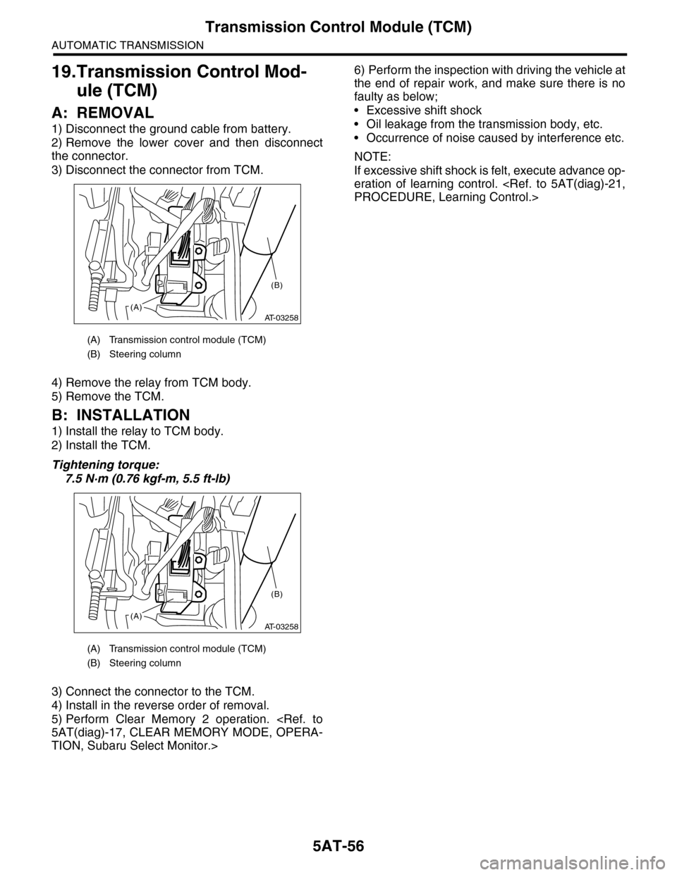
3) Disconnect the connector from TCM.
4) Remove the relay from TCM body.
5) Remove the TCM.
B: INSTALLATION
1) Install the relay to TCM body.
2) Install the TCM.
Tightening torque:
7.5 N·m (0.76 kgf-m, 5.5 ft-lb)
3) Connect the connector to the TCM.
4) Install in the reverse order of removal.
5) Perform Clear Memory 2 operation.
TION, Subaru Select Monitor.>
6) Perform the inspection with driving the vehicle at
the end of repair work, and make sure there is no
faulty as below;
•Excessive shift shock
•Oil leakage from the transmission body, etc.
•Occurrence of noise caused by interference etc.
NOTE:
If excessive shift shock is felt, execute advance op-
eration of learning control.
(A) Transmission control module (TCM)
(B) Steering column
(A) Transmission control module (TCM)
(B) Steering column
AT-03258(A)
(B)
AT-03258(A)
(B)
Page 2113 of 2453
5AT-97
AT Main Case
AUTOMATIC TRANSMISSION
24) Install the extension case.
25) Install the control valve body.
26) Install the converter case assembly to the
transmission case assembly.
27) Install the air breather hose.
28) Install the ATF filter pipe.
29) Install the oil charge pipe together with an O-
ring.
30) Install the torque converter assembly.
sembly.>
31) Install the transmission assembly to the vehi-
cle.
32) Perform Clear Memory 2 operation.
TION, Subaru Select Monitor.>
33) Perform the inspection with driving the vehicle
at the end of repair work, and make sure there is no
faulty as below;
•Excessive shift shock
•Oil leakage from the transmission body, etc.
•Occurrence of noise caused by interference etc.
NOTE:
If excessive shift shock is felt, execute advance op-
eration of learning control.
C: DISASSEMBLY
1. INPUT CLUTCH PACK ASSEMBLY
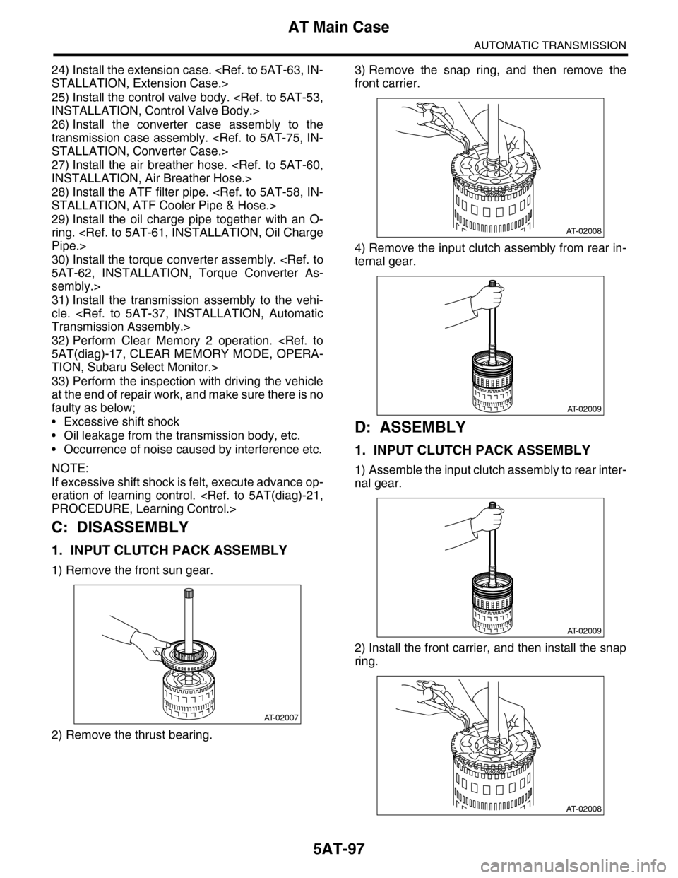
1) Remove the front sun gear.
2) Remove the thrust bearing.
3) Remove the snap ring, and then remove the
front carrier.
4) Remove the input clutch assembly from rear in-
ternal gear.
D: ASSEMBLY
1. INPUT CLUTCH PACK ASSEMBLY
1) Assemble the input clutch assembly to rear inter-
nal gear.
2) Install the front carrier, and then install the snap
ring.
AT-02007
AT-02008
AT-02009
AT-02009
AT-02008
Page 2119 of 2453
5AT(diag)-2
Basic Diagnostic Procedure
AUTOMATIC TRANSMISSION (DIAGNOSTICS)
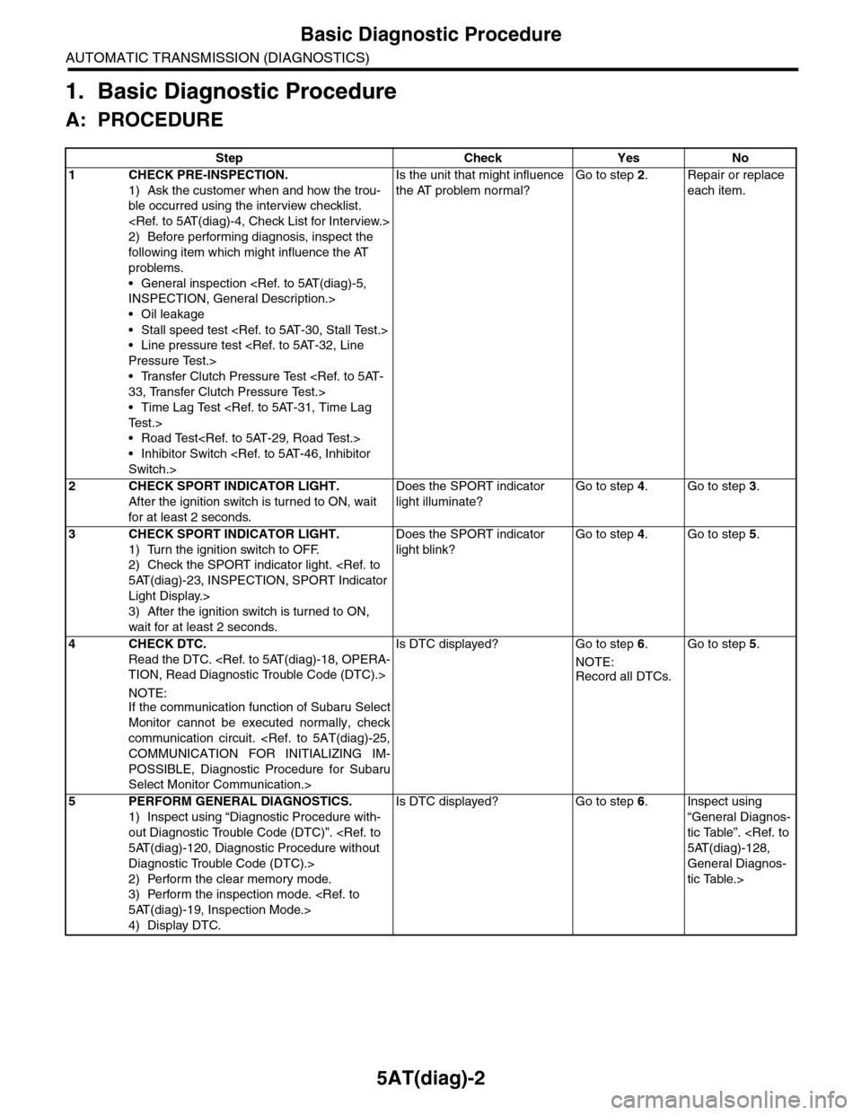
1. Basic Diagnostic Procedure
A: PROCEDURE
Step Check Yes No
1CHECK PRE-INSPECTION.
1) Ask the customer when and how the trou-
ble occurred using the interview checklist.
2) Before performing diagnosis, inspect the
following item which might influence the AT
problems.
•General inspection
•Oil leakage
•Stall speed test
•Line pressure test
•Transfer Clutch Pressure Test
•Time Lag Test
•Road Test
•Inhibitor Switch
Is the unit that might influence
the AT problem normal?
Go to step 2.Repair or replace
each item.
2CHECK SPORT INDICATOR LIGHT.
After the ignition switch is turned to ON, wait
for at least 2 seconds.
Does the SPORT indicator
light illuminate?
Go to step 4.Go to step 3.
3CHECK SPORT INDICATOR LIGHT.
1) Turn the ignition switch to OFF.
2) Check the SPORT indicator light.
Light Display.>
3) After the ignition switch is turned to ON,
wait for at least 2 seconds.
Does the SPORT indicator
light blink?
Go to step 4.Go to step 5.
4CHECK DTC.
Read the DTC.
NOTE:If the communication function of Subaru Select
Monitor cannot be executed normally, check
communication circuit.
POSSIBLE, Diagnostic Procedure for Subaru
Select Monitor Communication.>
Is DTC displayed? Go to step 6.
NOTE:
Record all DTCs.
Go to step 5.
5PERFORM GENERAL DIAGNOSTICS.
1) Inspect using “Diagnostic Procedure with-
out Diagnostic Trouble Code (DTC)”.
Diagnostic Trouble Code (DTC).>
2) Perform the clear memory mode.
3) Perform the inspection mode.
4) Display DTC.
Is DTC displayed? Go to step 6.Inspect using
“General Diagnos-
tic Table”.
General Diagnos-
tic Table.>
Page 2123 of 2453
5AT(diag)-6
General Description
AUTOMATIC TRANSMISSION (DIAGNOSTICS)
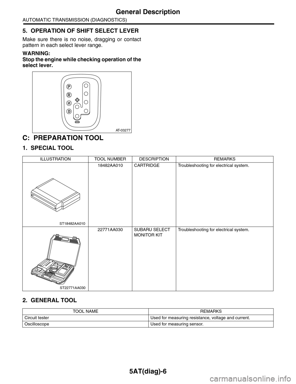
5. OPERATION OF SHIFT SELECT LEVER
Make sure there is no noise, dragging or contact
pattern in each select lever range.
WARNING:
Stop the engine while checking operation of the
select lever.
C: PREPARATION TOOL
1. SPECIAL TOOL
2. GENERAL TOOL
AT-03277
ILLUSTRATION TOOL NUMBER DESCRIPTION REMARKS
18482AA010 CARTRIDGE Troubleshooting for electrical system.
22771AA030 SUBARU SELECT
MONITOR KIT
Tr o u b l e s h o o t i n g f o r e l e c t r i c a l s y s t e m .
TOOL NAME REMARKS
Circuit tester Used for measuring resistance, voltage and current.
Oscilloscope Used for measuring sensor.
ST18482AA010
ST22771AA030
Page 2130 of 2453
5AT(diag)-13
Transmission Control Module (TCM) I/O Signal
AUTOMATIC TRANSMISSION (DIAGNOSTICS)
H&LR/C oil pressure
switch inputB55 8
While driving at 2nd of
manual mode
Pow er s up p ly
voltage—
While driving at 3rd —
5th of manual modeApprox. 0 V
Fr o nt veh ic l e sp e ed
sensor inputB55 7
While driving at 2nd and
20 km/h (12 MPH) of
manual mode
Approx. 530 —
610 rpm
—
Use the Subaru
Select Monitor.
While driving at 4th and
80 km/h (50 MPH) of
manual mode
Approx. 2160 —
2410 rpm
Use the Subaru
Select Monitor.
Inhibitor switch 1 input B55 4
Ignition switch ON, “P”
range4.0 — 5.0 V
—
Ignition switch ON, “N”
rangeLess than 1.5 V
Inhibitor switch 2 input B55 3
Ignition switch ON, “P”
range4.0 — 5.0 V
—
Ignition switch ON, “D”
rangeLess than 1.5 V
Accessory power sup-
plyB55 2Accessory switch ONPow er s up p ly
voltage—
Accessory switch OFF Approx. 0 V
Ignition power supply B55 1Ignition switch ONPow er s up p ly
voltage—
Ignition switch OFF Approx. 0 V
Rear vehicle speed
sensor inputB55 18
While driving at 2nd and
20 km/h (12 MPH) of
manual mode
Approx. 530 —
610 rpm
—
Use the Subaru
Select Monitor.
While driving at 4th and
80 km/h (50 MPH) of
manual mode
Approx. 2160 —
2410 rpm
Use the Subaru
Select Monitor.
Fr / B oi l p r e ssu r e
switch inputB55 17
Ignition switch ON,
engine ON, while driv-
ing at other than 4th
Approx. 0 V
—
Ignition switch ON,
engine ON, while driv-
ing at 4th
Pow er s up p ly
voltage
Tu r b i n e s p e e d s e n s o r
1 inputB55 16
2nd of manual mode,
turbine speed sensor is
2,000 rpm (Read from
Subaru Select Monitor)
Approx. 0 rpm
—
Use the Subaru
Select Monitor.
4th of manual mode, tur-
bine speed sensor is
2,000 rpm (Read from
Subaru Select Monitor)
Approx. 1,900
— 2,100 rpm
Use the Subaru
Select Monitor.
Range lock solenoid
outputB55 15
Ignition switch ON, while
stopping at “D” range
Approx. Power
Supply Voltage
–1.2 V7 — 21 Ω
Ignition switch ON, vehi-
cle speed at least 20 km/
h (12 MPH)
Approx. 0 V
Inhibitor switch 3 input B55 14
Ignition switch ON, “R”
range4.0 — 5.0 V
—
Ignition switch ON, “D”
rangeLess than 1.5 V
ItemConnector
No.
Te r m i n a l
No.Measuring condition Measured value
Resistance
between termi-
nal and chassis
ground
Remarks