2009 SUBARU TRIBECA monitor
[x] Cancel search: monitorPage 1544 of 2453
EN(H6DO)(diag)-383
Diagnostic Procedure with Diagnostic Trouble Code (DTC)
ENGINE (DIAGNOSTICS)
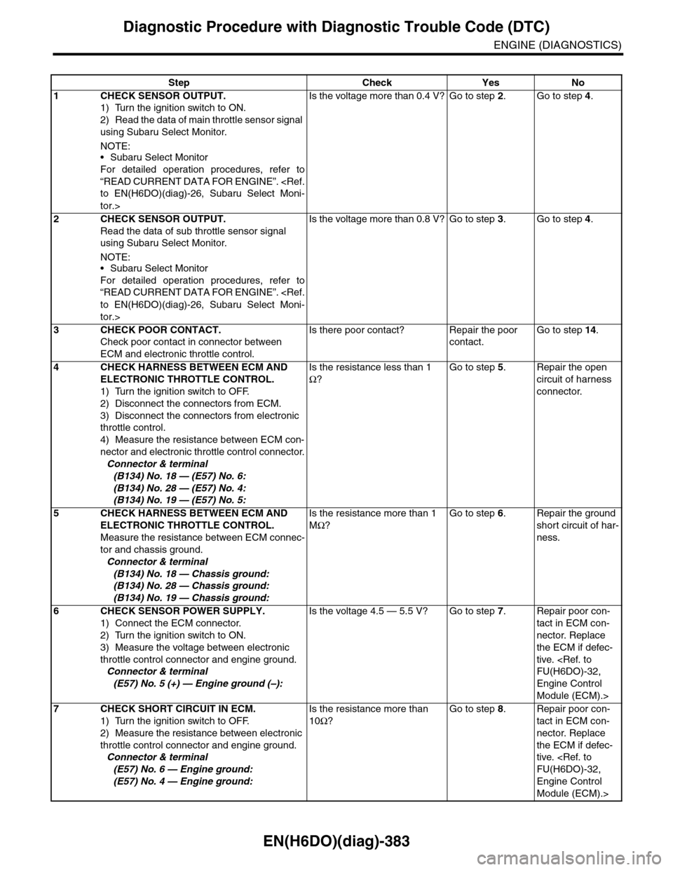
Step Check Yes No
1CHECK SENSOR OUTPUT.
1) Turn the ignition switch to ON.
2) Read the data of main throttle sensor signal
using Subaru Select Monitor.
NOTE:•Subaru Select Monitor
For detailed operation procedures, refer to
“READ CURRENT DATA FOR ENGINE”.
tor.>
Is the voltage more than 0.4 V? Go to step 2.Go to step 4.
2CHECK SENSOR OUTPUT.
Read the data of sub throttle sensor signal
using Subaru Select Monitor.
NOTE:•Subaru Select Monitor
For detailed operation procedures, refer to
“READ CURRENT DATA FOR ENGINE”.
tor.>
Is the voltage more than 0.8 V? Go to step 3.Go to step 4.
3CHECK POOR CONTACT.
Check poor contact in connector between
ECM and electronic throttle control.
Is there poor contact? Repair the poor
contact.
Go to step 14.
4CHECK HARNESS BETWEEN ECM AND
ELECTRONIC THROTTLE CONTROL.
1) Turn the ignition switch to OFF.
2) Disconnect the connectors from ECM.
3) Disconnect the connectors from electronic
throttle control.
4) Measure the resistance between ECM con-
nector and electronic throttle control connector.
Connector & terminal
(B134) No. 18 — (E57) No. 6:
(B134) No. 28 — (E57) No. 4:
(B134) No. 19 — (E57) No. 5:
Is the resistance less than 1
Ω?
Go to step 5.Repair the open
circuit of harness
connector.
5CHECK HARNESS BETWEEN ECM AND
ELECTRONIC THROTTLE CONTROL.
Measure the resistance between ECM connec-
tor and chassis ground.
Connector & terminal
(B134) No. 18 — Chassis ground:
(B134) No. 28 — Chassis ground:
(B134) No. 19 — Chassis ground:
Is the resistance more than 1
MΩ?
Go to step 6.Repair the ground
short circuit of har-
ness.
6CHECK SENSOR POWER SUPPLY.
1) Connect the ECM connector.
2) Turn the ignition switch to ON.
3) Measure the voltage between electronic
throttle control connector and engine ground.
Connector & terminal
(E57) No. 5 (+) — Engine ground (–):
Is the voltage 4.5 — 5.5 V? Go to step 7.Repair poor con-
tact in ECM con-
nector. Replace
the ECM if defec-
tive.
Engine Control
Module (ECM).>
7CHECK SHORT CIRCUIT IN ECM.
1) Turn the ignition switch to OFF.
2) Measure the resistance between electronic
throttle control connector and engine ground.
Connector & terminal
(E57) No. 6 — Engine ground:
(E57) No. 4 — Engine ground:
Is the resistance more than
10Ω?
Go to step 8.Repair poor con-
tact in ECM con-
nector. Replace
the ECM if defec-
tive.
Engine Control
Module (ECM).>
Page 1545 of 2453
EN(H6DO)(diag)-384
Diagnostic Procedure with Diagnostic Trouble Code (DTC)
ENGINE (DIAGNOSTICS)
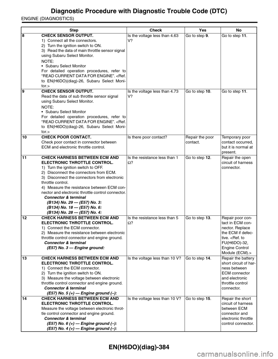
8CHECK SENSOR OUTPUT.
1) Connect all the connectors.
2) Turn the ignition switch to ON.
3) Read the data of main throttle sensor signal
using Subaru Select Monitor.
NOTE:
•Subaru Select Monitor
For detailed operation procedures, refer to
“READ CURRENT DATA FOR ENGINE”.
tor.>
Is the voltage less than 4.63
V?
Go to step 9.Go to step 11.
9CHECK SENSOR OUTPUT.
Read the data of sub throttle sensor signal
using Subaru Select Monitor.
NOTE:•Subaru Select Monitor
For detailed operation procedures, refer to
“READ CURRENT DATA FOR ENGINE”.
tor.>
Is the voltage less than 4.73
V?
Go to step 10.Go to step 11.
10 CHECK POOR CONTACT.
Check poor contact in connector between
ECM and electronic throttle control.
Is there poor contact? Repair the poor
contact.
Te m p o r a r y p o o r
contact occurred,
but it is normal at
present.
11 CHECK HARNESS BETWEEN ECM AND
ELECTRONIC THROTTLE CONTROL.
1) Turn the ignition switch to OFF.
2) Disconnect the connectors from ECM.
3) Disconnect the connectors from electronic
throttle control.
4) Measure the resistance between ECM con-
nector and electronic throttle control connector.
Connector & terminal
(B134) No. 29 — (E57) No. 3:
(B134) No. 18 — (E57) No. 6:
(B134) No. 28 — (E57) No. 4:
Is the resistance less than 1
Ω?
Go to step 12.Repair the open
circuit of harness
connector.
12 CHECK HARNESS BETWEEN ECM AND
ELECTRONIC THROTTLE CONTROL.
1) Connect the ECM connector.
2) Measure the resistance between electronic
throttle control connector and engine ground.
Connector & terminal
(E57) No. 3 — Engine ground:
Is the resistance less than 5
Ω?
Go to step 13.Repair poor con-
tact in ECM con-
nector. Replace
the ECM if defec-
tive.
Engine Control
Module (ECM).>
13 CHECK HARNESS BETWEEN ECM AND
ELECTRONIC THROTTLE CONTROL.
1) Connect the ECM connector.
2) Turn the ignition switch to ON.
3) Measure the voltage between electronic
throttle control connector and engine ground.
Connector & terminal
(E57) No. 5 (+) — Engine ground (–):
Is the voltage less than 10 V? Go to step 14.Repair the battery
short circuit of har-
ness between
ECM connector
and electronic
throttle control
connector.
14 CHECK HARNESS BETWEEN ECM AND
ELECTRONIC THROTTLE CONTROL.
Measure the voltage between electronic throt-
tle control connector and engine ground.
Connector & terminal
(E57) No. 6 (+) — Engine ground (–):
(E57) No. 4 (+) — Engine ground (–):
Is the voltage less than 10 V? Go to step 15.Repair the short
circuit of harness
between ECM
connector and
electronic throttle
control connector.
Step Check Yes No
Page 1548 of 2453
EN(H6DO)(diag)-387
Diagnostic Procedure with Diagnostic Trouble Code (DTC)
ENGINE (DIAGNOSTICS)
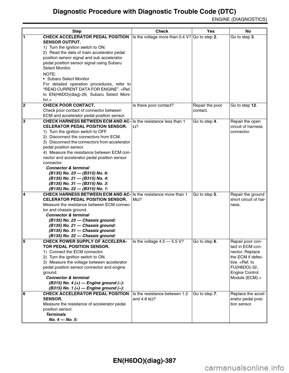
Step Check Yes No
1CHECK ACCELERATOR PEDAL POSITION
SENSOR OUTPUT.
1) Turn the ignition switch to ON.
2) Read the data of main accelerator pedal
position sensor signal and sub accelerator
pedal position sensor signal using Subaru
Select Monitor.
NOTE:•Subaru Select Monitor
For detailed operation procedures, refer to
“READ CURRENT DATA FOR ENGINE”.
tor.>
Is the voltage more than 0.4 V? Go to step 2.Go to step 3.
2CHECK POOR CONTACT.
Check poor contact of connector between
ECM and accelerator pedal position sensor.
Is there poor contact? Repair the poor
contact.
Go to step 12.
3CHECK HARNESS BETWEEN ECM AND AC-
CELERATOR PEDAL POSITION SENSOR.
1) Turn the ignition switch to OFF.
2) Disconnect the connectors from ECM.
3) Disconnect the connectors from accelerator
pedal position sensor.
4) Measure the resistance between ECM con-
nector and accelerator pedal position sensor
connector.
Connector & terminal
(B135) No. 23 — (B315) No. 6:
(B135) No. 21 — (B315) No. 4:
(B135) No. 31 — (B315) No. 3:
(B135) No. 22 — (B315) No. 1:
Is the resistance less than 1
Ω?
Go to step 4.Repair the open
circuit of harness
connector.
4CHECK HARNESS BETWEEN ECM AND AC-
CELERATOR PEDAL POSITION SENSOR.
Measure the resistance between ECM connec-
tor and chassis ground.
Connector & terminal
(B135) No. 23 — Chassis ground:
(B135) No. 21 — Chassis ground:
(B135) No. 31 — Chassis ground:
(B135) No. 22 — Chassis ground:
Is the resistance more than 1
MΩ?
Go to step 5.Repair the ground
short circuit of har-
ness.
5CHECK POWER SUPPLY OF ACCELERA-
TOR PEDAL POSITION SENSOR.
1) Connect the ECM connector.
2) Turn the ignition switch to ON.
3) Measure the voltage between accelerator
pedal position sensor connector and engine
ground.
Connector & terminal
(B315) No. 4 (+) — Engine ground (–):
(B315) No. 1 (+) — Engine ground (–):
Is the voltage 4.5 — 5.5 V? Go to step 6.Repair poor con-
tact in ECM con-
nector. Replace
the ECM if defec-
tive.
Engine Control
Module (ECM).>
6CHECK ACCELERATOR PEDAL POSITION
SENSOR.
Measure the resistance of accelerator pedal
position sensor.
Te r m i n a l s
No. 4 — No. 5:
Is the resistance between 1.2
and 4.8 kΩ?
Go to step 7.Replace the accel-
erator pedal posi-
tion sensor.
Page 1549 of 2453
EN(H6DO)(diag)-388
Diagnostic Procedure with Diagnostic Trouble Code (DTC)
ENGINE (DIAGNOSTICS)
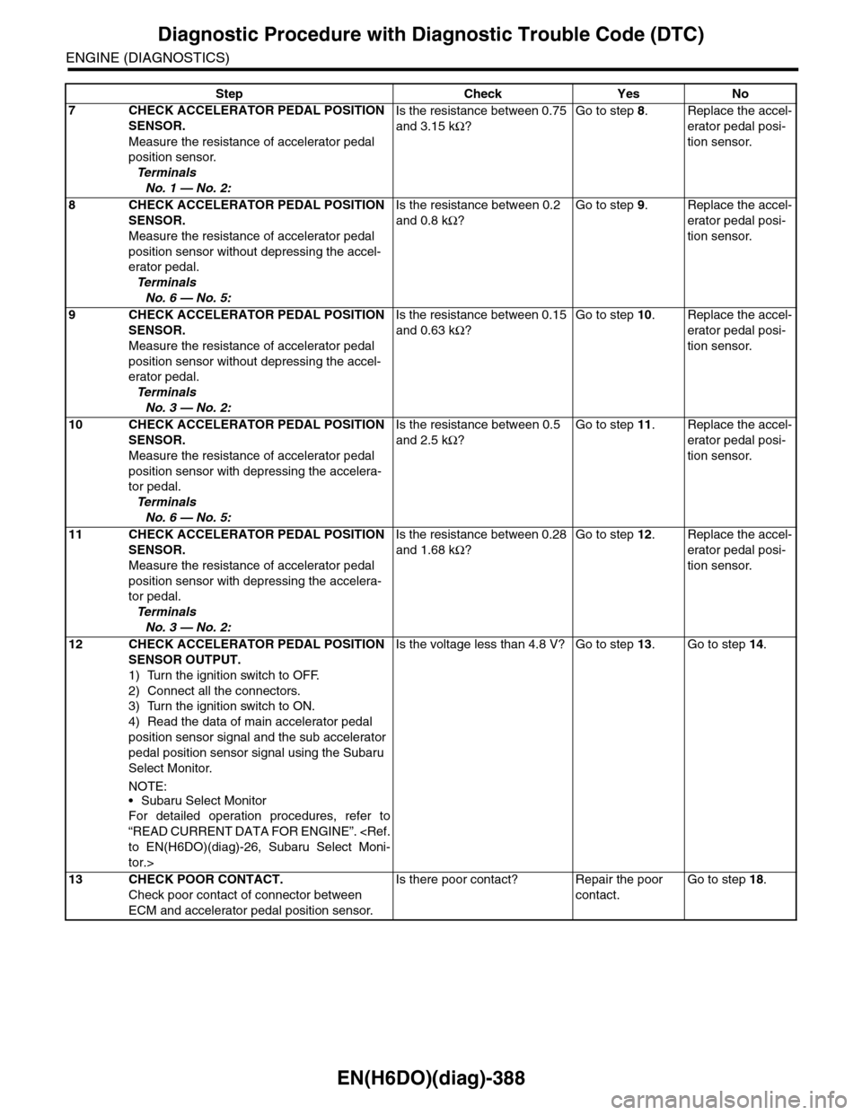
7CHECK ACCELERATOR PEDAL POSITION
SENSOR.
Measure the resistance of accelerator pedal
position sensor.
Te r m i n a l s
No. 1 — No. 2:
Is the resistance between 0.75
and 3.15 kΩ?
Go to step 8.Replace the accel-
erator pedal posi-
tion sensor.
8CHECK ACCELERATOR PEDAL POSITION
SENSOR.
Measure the resistance of accelerator pedal
position sensor without depressing the accel-
erator pedal.
Te r m i n a l s
No. 6 — No. 5:
Is the resistance between 0.2
and 0.8 kΩ?
Go to step 9.Replace the accel-
erator pedal posi-
tion sensor.
9CHECK ACCELERATOR PEDAL POSITION
SENSOR.
Measure the resistance of accelerator pedal
position sensor without depressing the accel-
erator pedal.
Te r m i n a l s
No. 3 — No. 2:
Is the resistance between 0.15
and 0.63 kΩ?
Go to step 10.Replace the accel-
erator pedal posi-
tion sensor.
10 CHECK ACCELERATOR PEDAL POSITION
SENSOR.
Measure the resistance of accelerator pedal
position sensor with depressing the accelera-
tor pedal.
Te r m i n a l s
No. 6 — No. 5:
Is the resistance between 0.5
and 2.5 kΩ?
Go to step 11.Replace the accel-
erator pedal posi-
tion sensor.
11 CHECK ACCELERATOR PEDAL POSITION
SENSOR.
Measure the resistance of accelerator pedal
position sensor with depressing the accelera-
tor pedal.
Te r m i n a l s
No. 3 — No. 2:
Is the resistance between 0.28
and 1.68 kΩ?
Go to step 12.Replace the accel-
erator pedal posi-
tion sensor.
12 CHECK ACCELERATOR PEDAL POSITION
SENSOR OUTPUT.
1) Turn the ignition switch to OFF.
2) Connect all the connectors.
3) Turn the ignition switch to ON.
4) Read the data of main accelerator pedal
position sensor signal and the sub accelerator
pedal position sensor signal using the Subaru
Select Monitor.
NOTE:
•Subaru Select Monitor
For detailed operation procedures, refer to
“READ CURRENT DATA FOR ENGINE”.
tor.>
Is the voltage less than 4.8 V? Go to step 13.Go to step 14.
13 CHECK POOR CONTACT.
Check poor contact of connector between
ECM and accelerator pedal position sensor.
Is there poor contact? Repair the poor
contact.
Go to step 18.
Step Check Yes No
Page 1551 of 2453
EN(H6DO)(diag)-390
Diagnostic Procedure with Diagnostic Trouble Code (DTC)
ENGINE (DIAGNOSTICS)
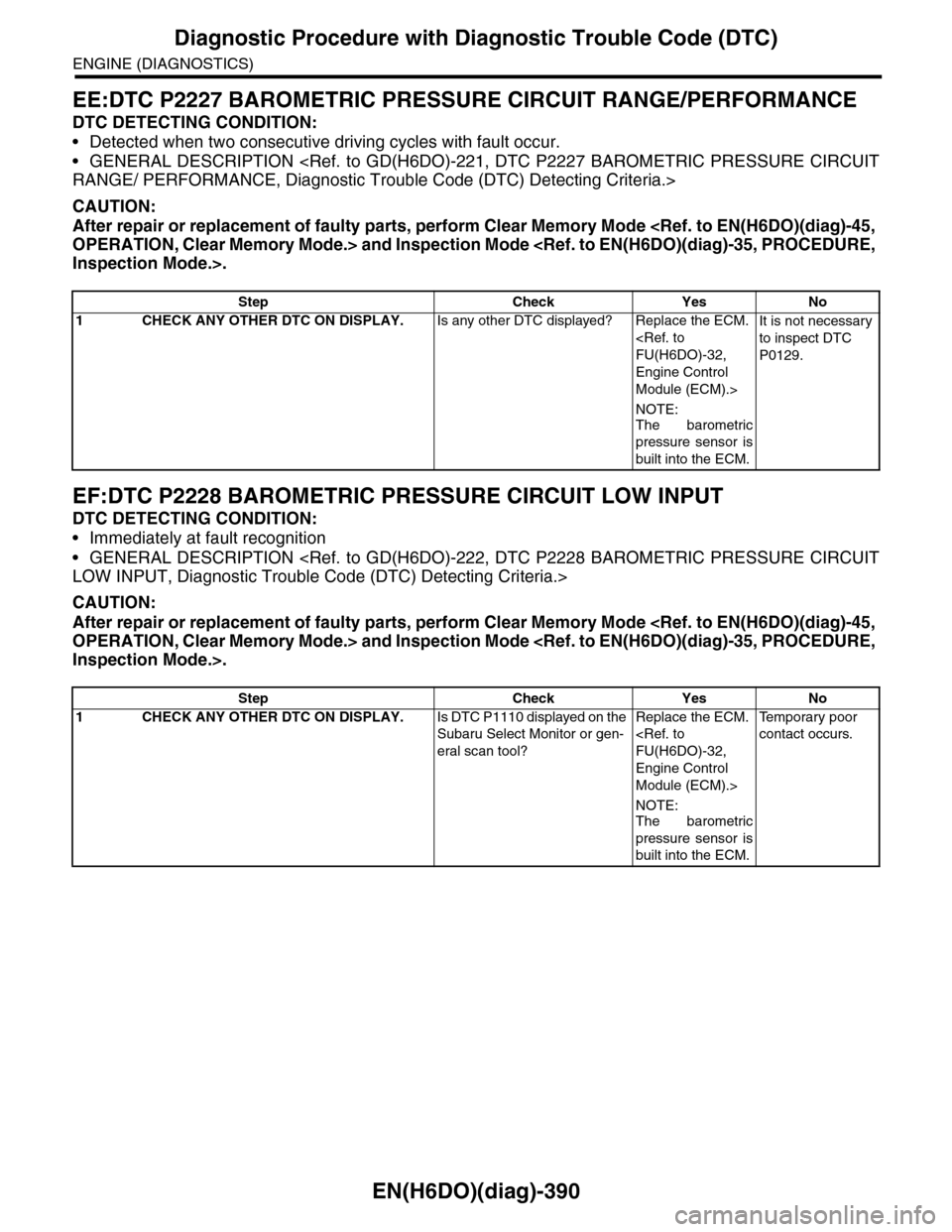
EE:DTC P2227 BAROMETRIC PRESSURE CIRCUIT RANGE/PERFORMANCE
DTC DETECTING CONDITION:
•Detected when two consecutive driving cycles with fault occur.
•GENERAL DESCRIPTION
CAUTION:
After repair or replacement of faulty parts, perform Clear Memory Mode
EF:DTC P2228 BAROMETRIC PRESSURE CIRCUIT LOW INPUT
DTC DETECTING CONDITION:
•Immediately at fault recognition
•GENERAL DESCRIPTION
CAUTION:
After repair or replacement of faulty parts, perform Clear Memory Mode
Step Check Yes No
1CHECK ANY OTHER DTC ON DISPLAY.Is any other DTC displayed? Replace the ECM.
Engine Control
Module (ECM).>
NOTE:
The barometric
pressure sensor is
built into the ECM.
It is not necessary
to inspect DTC
P0129.
Step Check Yes No
1CHECK ANY OTHER DTC ON DISPLAY.Is DTC P1110 displayed on the
Subaru Select Monitor or gen-
eral scan tool?
Replace the ECM.
Engine Control
Module (ECM).>
NOTE:The barometric
pressure sensor is
built into the ECM.
Te m p o r a r y p o o r
contact occurs.
Page 1552 of 2453
EN(H6DO)(diag)-391
Diagnostic Procedure with Diagnostic Trouble Code (DTC)
ENGINE (DIAGNOSTICS)
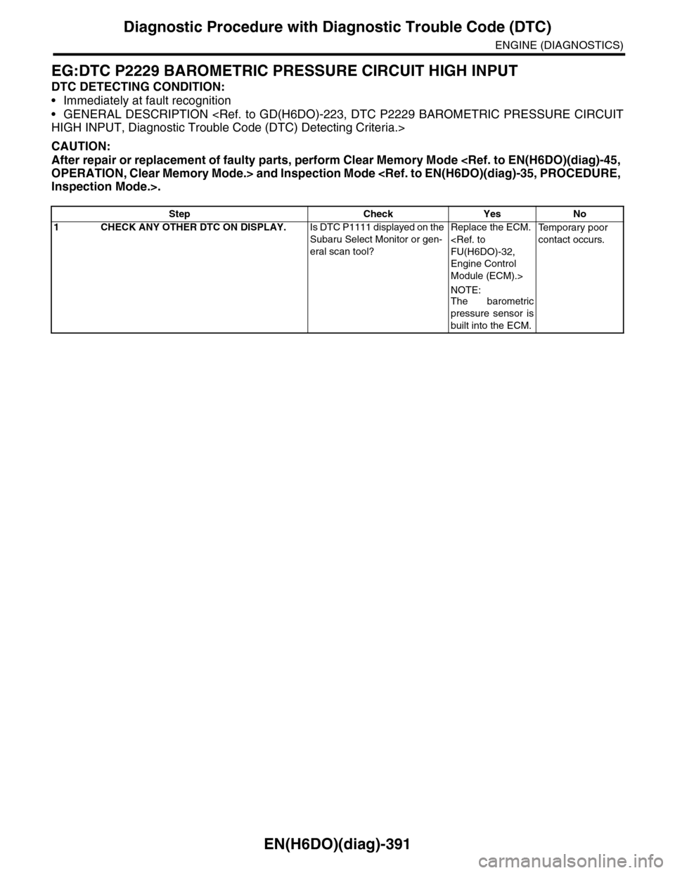
EG:DTC P2229 BAROMETRIC PRESSURE CIRCUIT HIGH INPUT
DTC DETECTING CONDITION:
•Immediately at fault recognition
•GENERAL DESCRIPTION
CAUTION:
After repair or replacement of faulty parts, perform Clear Memory Mode
Step Check Yes No
1CHECK ANY OTHER DTC ON DISPLAY.Is DTC P1111 displayed on the
Subaru Select Monitor or gen-
eral scan tool?
Replace the ECM.
Engine Control
Module (ECM).>
NOTE:
The barometric
pressure sensor is
built into the ECM.
Te m p o r a r y p o o r
contact occurs.
Page 1571 of 2453
FU(H6DO)-10
General Description
FUEL INJECTION (FUEL SYSTEMS)
C: CAUTION
•Wear work clothing, including a cap, protective goggles and protective shoes during operation.
•Remove contamination including dirt and corrosion before removal, installation or disassembly.
•Keep the disassembled parts in order and protect them from dust and dirt.
•Before removal, installation or disassembly, be sure to clarify the failure. Avoid unnecessary removal, in-
stallation, disassembly and replacement.
•Be careful not to burn yourself, because each part on the vehicle is hot after running.
•Be sure to tighten fasteners including bolts and nuts to the specified torque.
•Place shop jacks or rigid racks at the specified points.
•Before disconnecting connectors of sensors or units, be sure to disconnect the ground cable from the bat-
tery.
•Place “NO FIRE” signs near the working area.
•Be careful not to spill fuel on the floor.
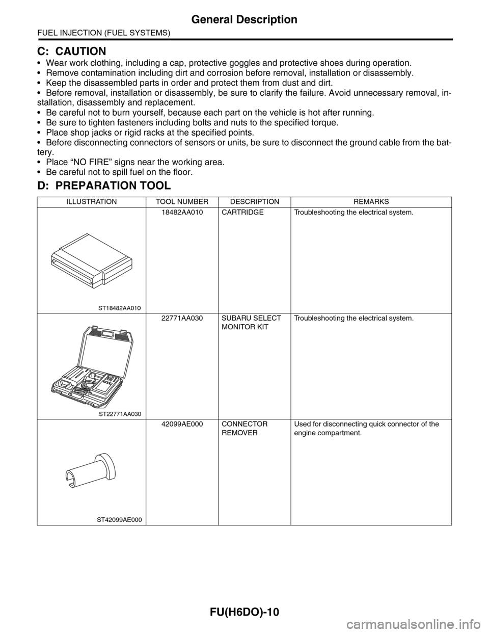
D: PREPARATION TOOL
ILLUSTRATION TOOL NUMBER DESCRIPTION REMARKS
18482AA010 CARTRIDGE Troubleshooting the electrical system.
22771AA030 SUBARU SELECT
MONITOR KIT
Tr o u b l e s h o o t i n g t h e e l e c t r i c a l s y s t e m .
42099AE000 CONNECTOR
REMOVER
Used for disconnecting quick connector of the
engine compartment.
ST18482AA010
ST22771AA030
ST42099AE000
Page 1716 of 2453
GD(H6DO)-104
Diagnostic Trouble Code (DTC) Detecting Criteria
GENERAL DESCRIPTION
BN:DTC P0301 CYLINDER 1 MISFIRE DETECTED
1. OUTLINE OF DIAGNOSIS
Detect the presence of misfire occurrence. (Revolution fluctuation method)
Monitoring Misfire which influences exhaust deterioration (1.5 times of FTP) and catalyst damage is made
obligatory by the law. Misfire affecting these two has three patterns below. Intermittent misfire (Different cyl-
inders misfire intermittently.):
•Intermittent misfire (The same cylinder misfires in random, or different cylinders misfire in random.): FTP
1.5 times misfire
•Every time misfire (The same cylinder misfires every time.): FTP 1.5 times misfire, Catalyst damage misfire
The following detecting methods are adopted for these detection.
1) Intermittent misfire: FTP 1.5 times misfire
•120° Interval Difference Method
•360° Interval Difference Method (whole range)
•720° Interval Difference Method (3,000 rpm or less)
2) Misfire every time: FTP 1.5 times misfire, Catalyst damage misfire
•360° Interval Difference Method
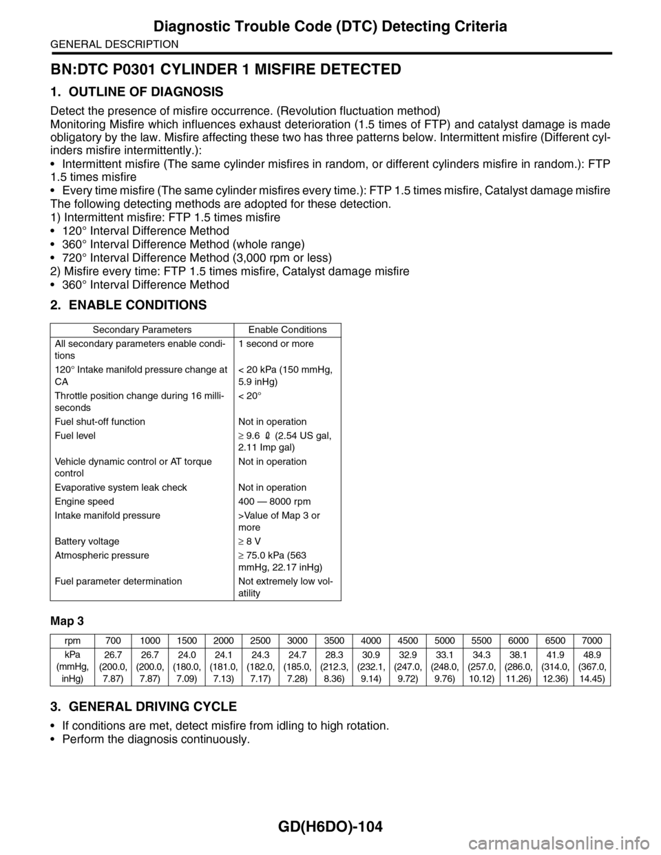
2. ENABLE CONDITIONS
Map 3
3. GENERAL DRIVING CYCLE
•If conditions are met, detect misfire from idling to high rotation.
•Perform the diagnosis continuously.
Secondary Parameters Enable Conditions
All secondary parameters enable condi-
tions
1 second or more
120° Intake manifold pressure change at
CA
< 20 kPa (150 mmHg,
5.9 inHg)
Throttle position change during 16 milli-
seconds
< 20°
Fuel shut-off function Not in operation
Fuel level≥ 9.6 2 (2.54 US gal,
2.11 Imp gal)
Ve h i c l e d y n a m i c c o n t r o l o r AT t o r q u e
control
Not in operation
Evaporative system leak check Not in operation
Engine speed 400 — 8000 rpm
Intake manifold pressure >Value of Map 3 or
more
Battery voltage≥ 8 V
Atmospheric pressure≥ 75.0 kPa (563
mmHg, 22.17 inHg)
Fuel parameter determination Not extremely low vol-
atility
rpm 700 1000 1500 2000 2500 3000 3500 4000 4500 5000 5500 6000 6500 7000
kPa
(mmHg,
inHg)
26.7
(200.0,
7.87)
26.7
(200.0,
7.87)
24.0
(180.0,
7.09)
24.1
(181.0,
7.13)
24.3
(182.0,
7.17)
24.7
(185.0,
7.28)
28.3
(212.3,
8.36)
30.9
(232.1,
9.14)
32.9
(247.0,
9.72)
33.1
(248.0,
9.76)
34.3
(257.0,
10.12)
38.1
(286.0,
11.26)
41.9
(314.0,
12.36)
48.9
(367.0,
14.45)